Swapping a Flat Tappet to a Hydraulic Roller Camshaft
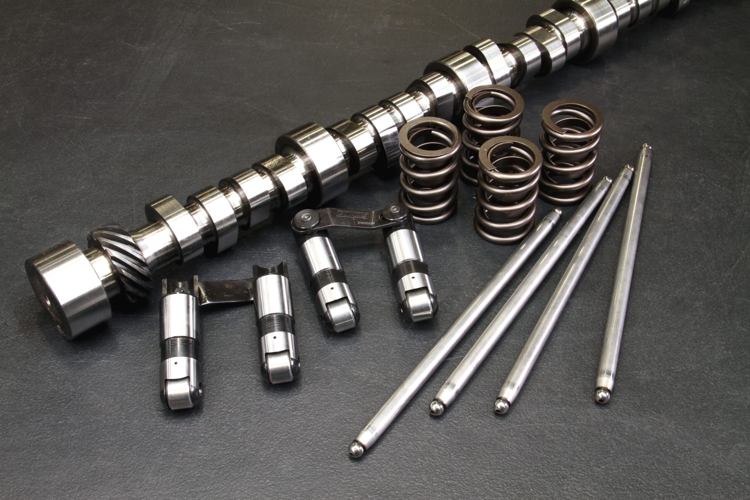
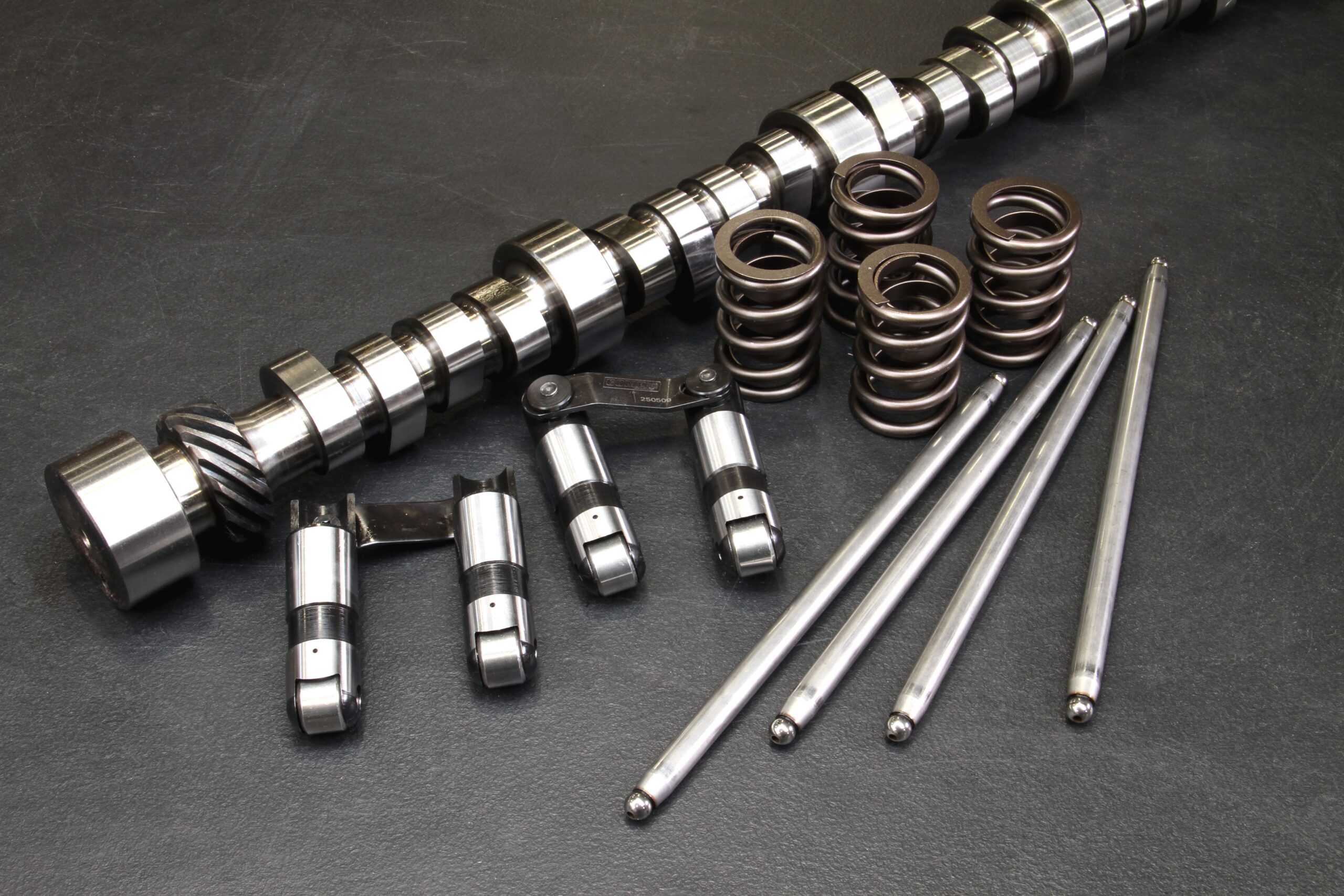
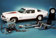
The Comp Cams kit (PN K11-413-8), which included an Xtreme Energy hydraulic roller camshaft, roller lifters, valvesprings, push rods, a timing set, and even a cam button, which is necessary on Chevy engines converting to a roller cam.
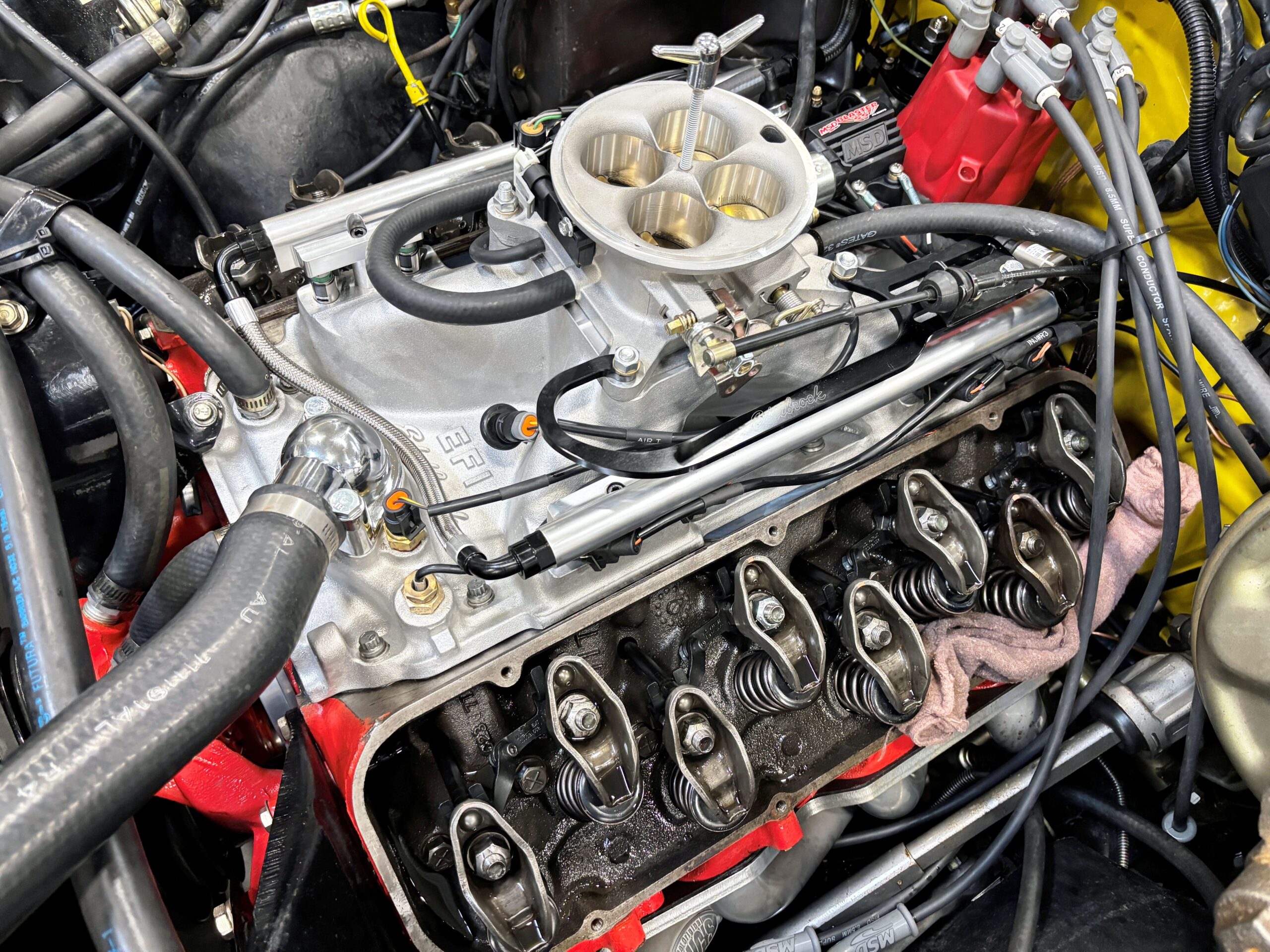
Steven Nissen rolled his 1971 big-block Chevelle into Stellar Rod & Custom with a seemingly simple request: Swap the old carburetor for fuel injection. The Detroit-area shop obliged and installed an Edelbrock EFI system.
But there was a problem. As soon as Stellar connected the control system and turned the ignition key, the engine began popping and even backfiring through the throttle body. It wasn’t a tuning issue, and what Nissen previously thought was an out-of-tune carburetor or bad ignition timing pointed to a different culprit.
“We knew right away something else was going on,” Stellar owner Mike Brimm says. “The engine had been rebuilt and didn’t have many miles on it, but the exhaust pops seemed to suggest the valve timing was off. It could have been a sticking valve, but the engine also had a flat-tappet camshaft; the bigger worry was its lobes and lifters.”
Backfires and a popping exhaust were clues that not all was right with this big-block Chevy 402, which was powering a 1971 Chevelle that had just received an Edelbrock EFI upgrade.
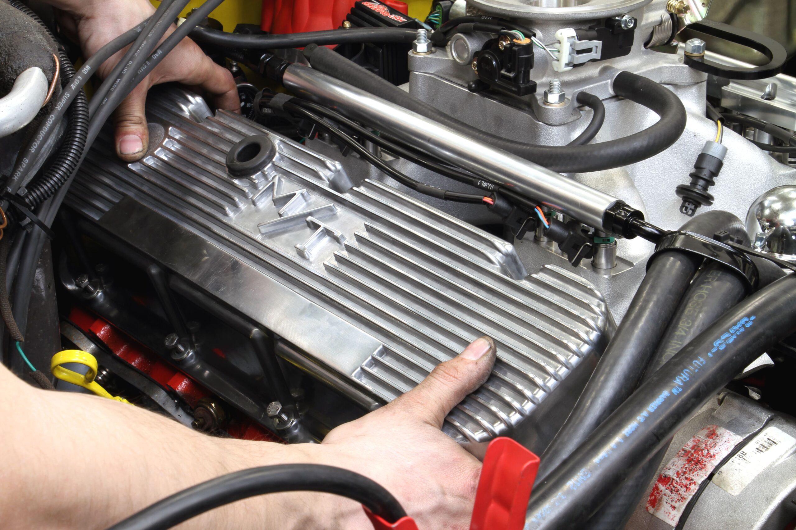
After removing the valve covers, a few of the rockers appeared to be a little lazy when the engine was running, indicating the valves weren’t opening or closing properly. A follow-up inspection with a borescope revealed jagged edges on a couple of the lifters. Three of them had “mushroomed,” too. Not good.
After that troubling discovery, Nissen had the Stellar team remove the engine and inspect it. When the camshaft was taken out, Brimm’s concern was confirmed: several lobes were destroyed, and the cam was unusable. There were many possible reasons the flat-tappet (mechanical) camshaft could have failed, but the most likely cause was a lack of zinc in the motor oil. Zinc is essential for preventing wear in a flat-tappet valvetrain.
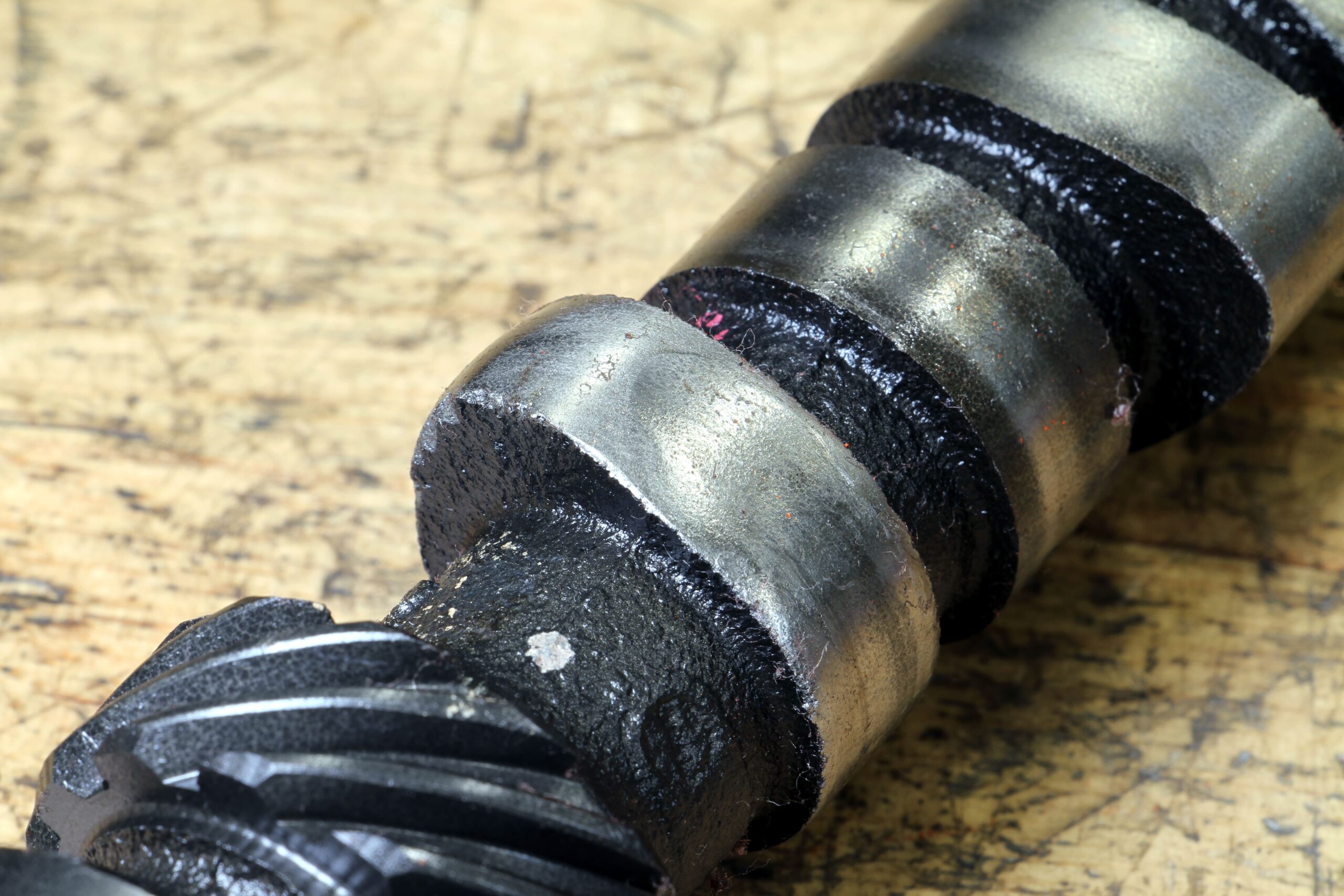
The damage to the flat-tappet cam is easy to see. Since the pressure at the contact point between the crown of the solid lifter and the cam lobe is very high—possibly 200,000 psi or more—the damage likely resulted from inadequate wear protection from the motor oil. In addition to the flat spot on the lobe, notice the divots along its edge. The missing metal ended up in the oil pan.
It would have been easy to slip a replacement mechanical camshaft into the block, but switching to a hydraulic roller camshaft made more sense. Flat-tappet supporters will argue about the performance benefits, like greater lift and higher rpm potential, but Nissen’s A-body was just a street cruiser, so those factors didn’t really matter.
In fact, without the need for periodic valve-lash adjustments or concerns about “wiping out” the lobes—assuming the camshaft was installed and broken in properly—the low-maintenance nature of a hydraulic roller made it a much more practical choice. Additionally, the matching roller lifters would also reduce the load on the valvetrain, freeing up a few horsepower in daily driving compared to the flat-tappet design.
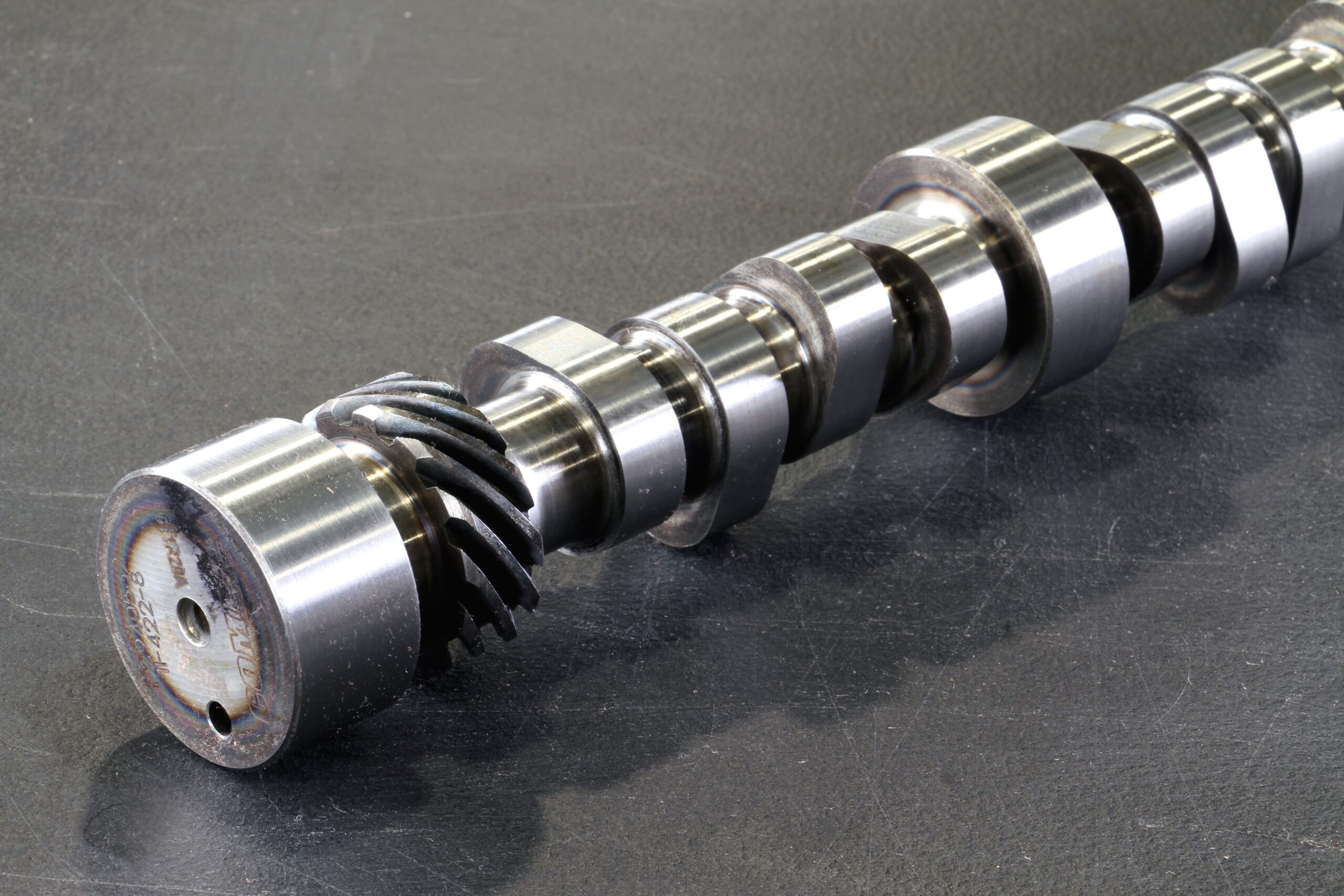
The cam specifications include a 0.510-inch lift for both the intake and exhaust valves, with durations of 212 and 218 degrees at 0.050-inch lift. The lobe separation angle is a moderate 110 degrees. This results in lower valve overlap, providing stronger low-end power and good vacuum for power brakes.
What’s not to like, right? Well, there are several considerations and upgrades to support when switching to a roller camshaft, and that’s the focus of this story. Along with the camshaft itself, nearly all the valvetrain components must be changed, along with a few other details—and if they aren’t done properly, the results can be as disastrous as a wiped-out flat-tappet camshaft.
“Timing is literally everything in an engine,” Brimm says. “All the valvetrain components must be spec’d perfectly to ensure valve timing is spot-on.”
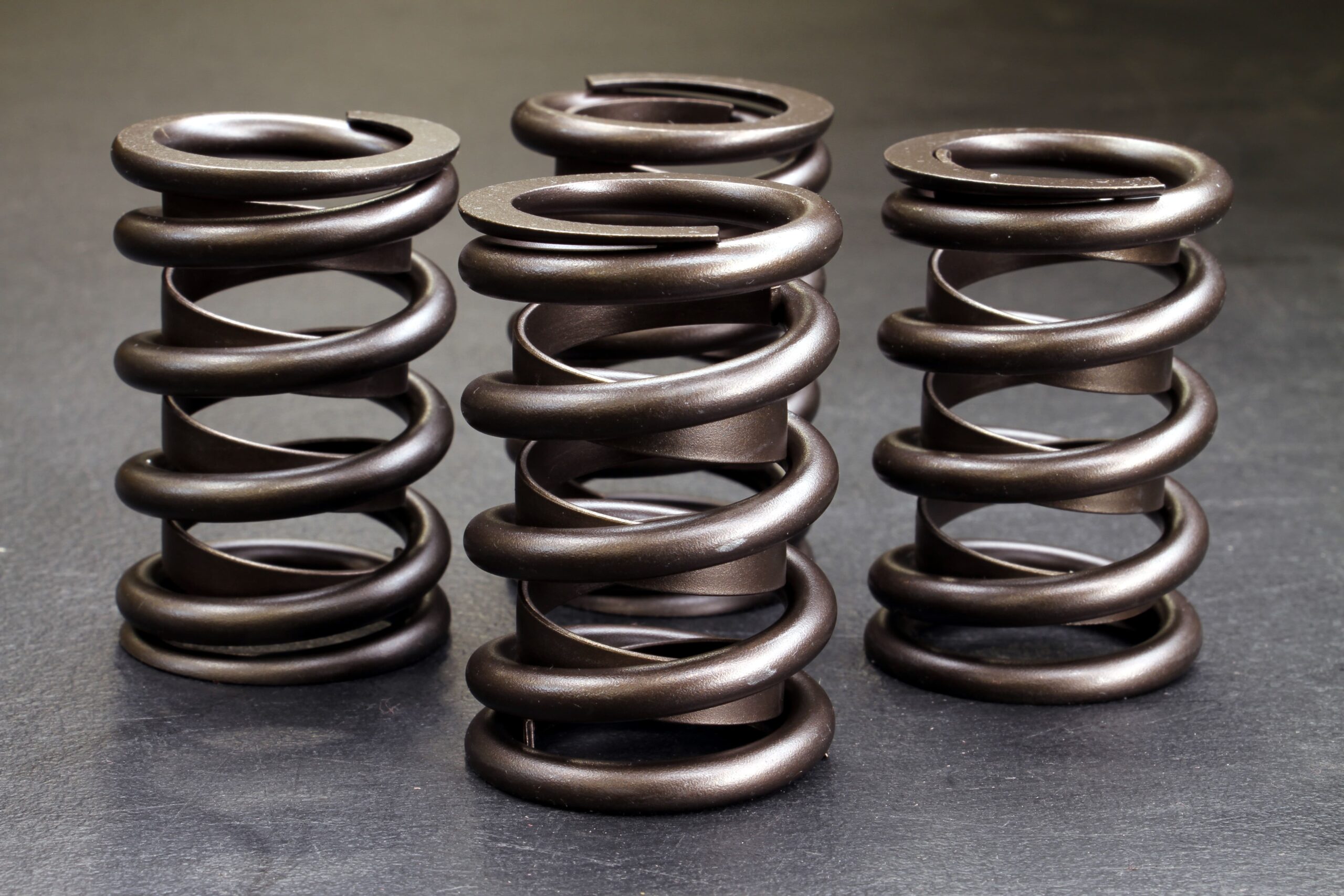
Also included in the kit was a set of COMP’s single-coil valvesprings (PN 26911-16). Specs include a 1.85-inch installed height, a spring rate of 410 lb-in, and a 387-pound open load at 1.20 inches.
For Nissen’s engine, Stellar went with an inclusive kit from Comp Cams, which included an Xtreme Energy hydraulic roller camshaft, roller lifters, valvesprings, push rods, a timing set, and even a cam button, which is necessary on Chevy engines converting to a roller cam. The kit is available directly from Comp and from popular retail outlets.
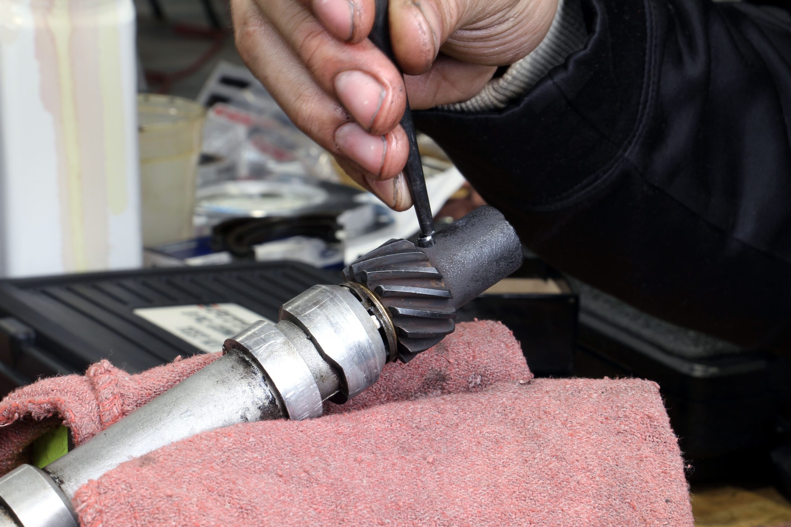
Since most roller camshafts are made of billet steel rather than cast iron, their distributor gear can cause excessive wear against a standard, softer cast-iron distributor gear. Therefore, the distributor gear must be replaced with a hardened, melonite-treated steel gear, the most common and cost-effective option, like the one shown here. Bronze and composite gears are also available. Additionally, a hardened fuel pump pushrod must be used on engines equipped with a mechanical fuel pump.
One thing not included in, but essential for a roller cam upgrade, was the hardened drive gear for the distributor. Additionally, a hardened fuel pump pushrod is necessary for engines still using a mechanical pump, but since the engine in this project used an electric fuel pump for its fuel injection system, it wasn’t needed.
With all the parts on hand, the installation was fairly straightforward, but the rocker arms didn’t quite fit right. They were a bit wobbly, and it turned out the pushrods, while correctly sized for a stock engine, didn’t quite fit with the rebuilt big-block.
“We didn’t know the details of the rebuild, so we didn’t know how much the block and heads had been machined,” Brimm says. “Those details stack up on one another and can affect the valvetrain geometry. In some cases, you can make the stock-length pushrods work, but in this case, we needed an all-new set.”
With everything buttoned up in the car, break-in oil is used in the engine and the rpm is immediately raised to between 2,000 and 2,500 rpm. This must be done for 30 minutes, with the rpm varying within that range to ensure adequate oiling of all the new components. After that, the break-in oil is drained and the filter is removed, with regular motor oil and a new filter installed. Another oil change after about 500 miles of driving is a good idea, too. After that, the cam should be good for the long haul.
After that was sorted, the engine went back together, and Nissen’s Chevelle was running better than ever. The maintenance-free hydraulic roller cam, combined with the engine’s EFI system, gave the classic A-body a contemporary rejuvenation, but Brimm reminds us that nothing in vintage car projects should be taken for granted.
“From the original issues that revealed the bad camshaft to selecting the right cam kit to even determining the correct pushrods, you can’t make assumptions,” he says. “Every step requires careful examination, preparation, and execution.”
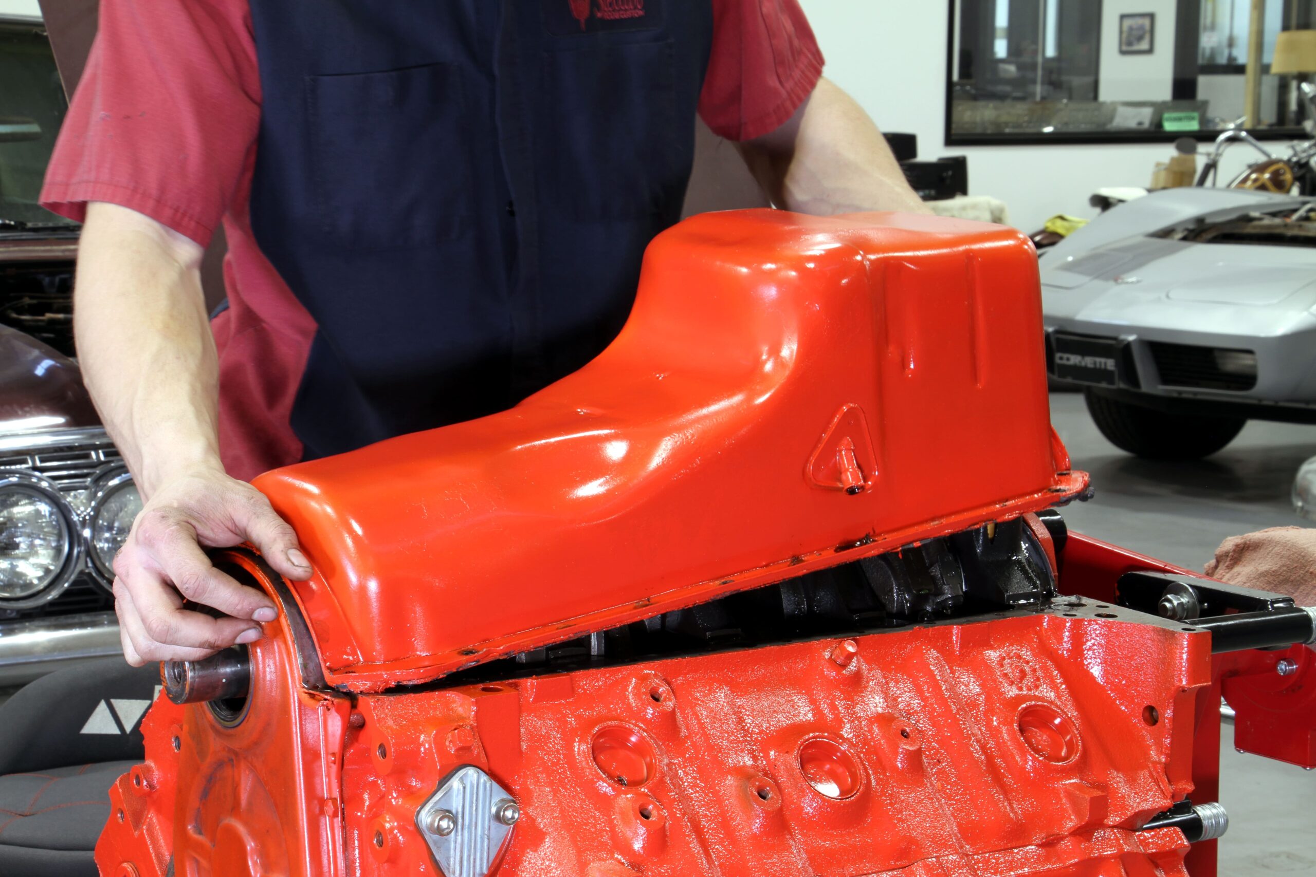
After initial digging suggested valvetrain problems, Stellar Rod & Custom removed the engine from the car and began tearing it down.
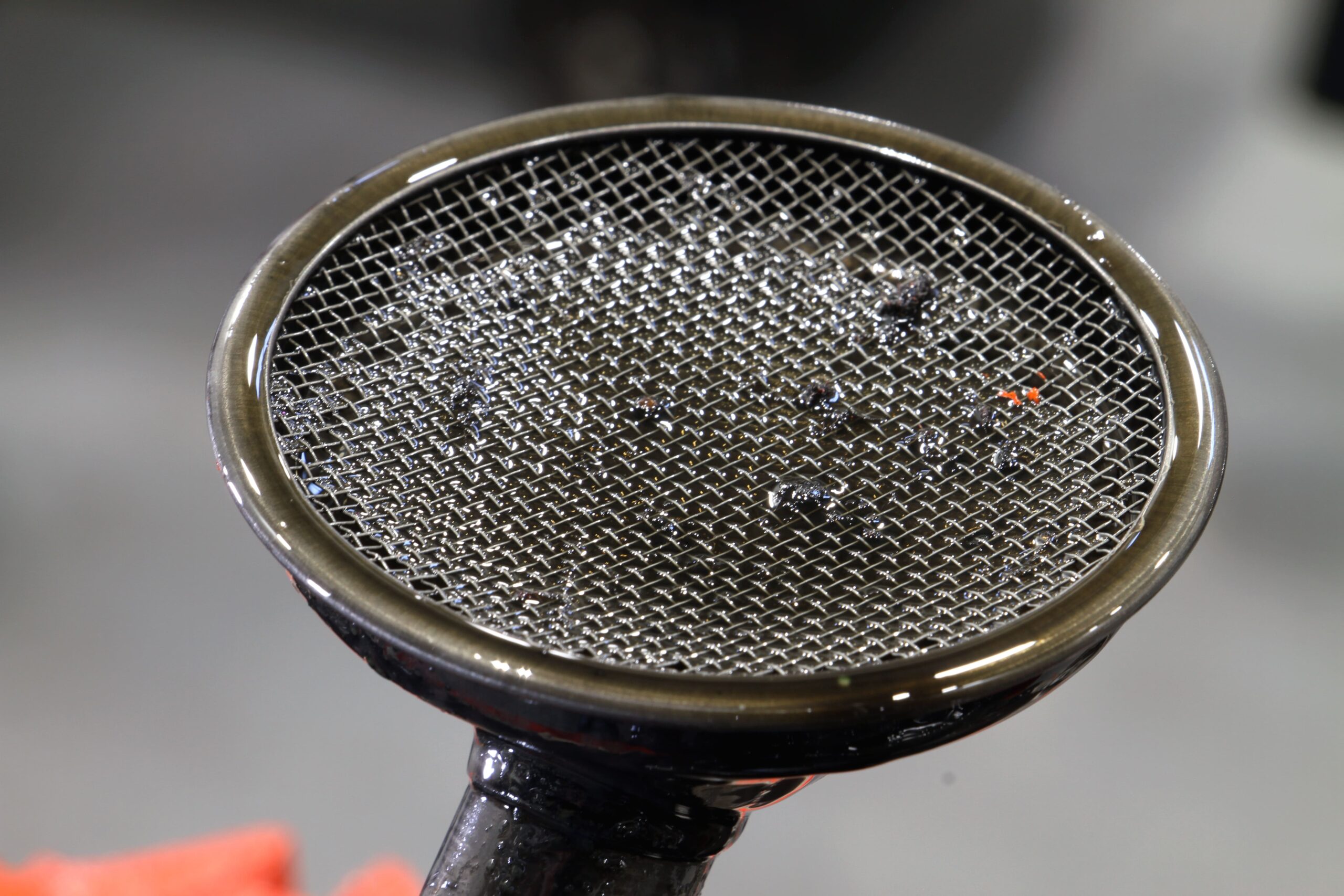
Nothing triggers a sinking feeling quite like discovering particles on the oil pump pickup. This engine had them and, after seeing lifter issues with a borescope, it all but confirmed the camshaft was a goner.
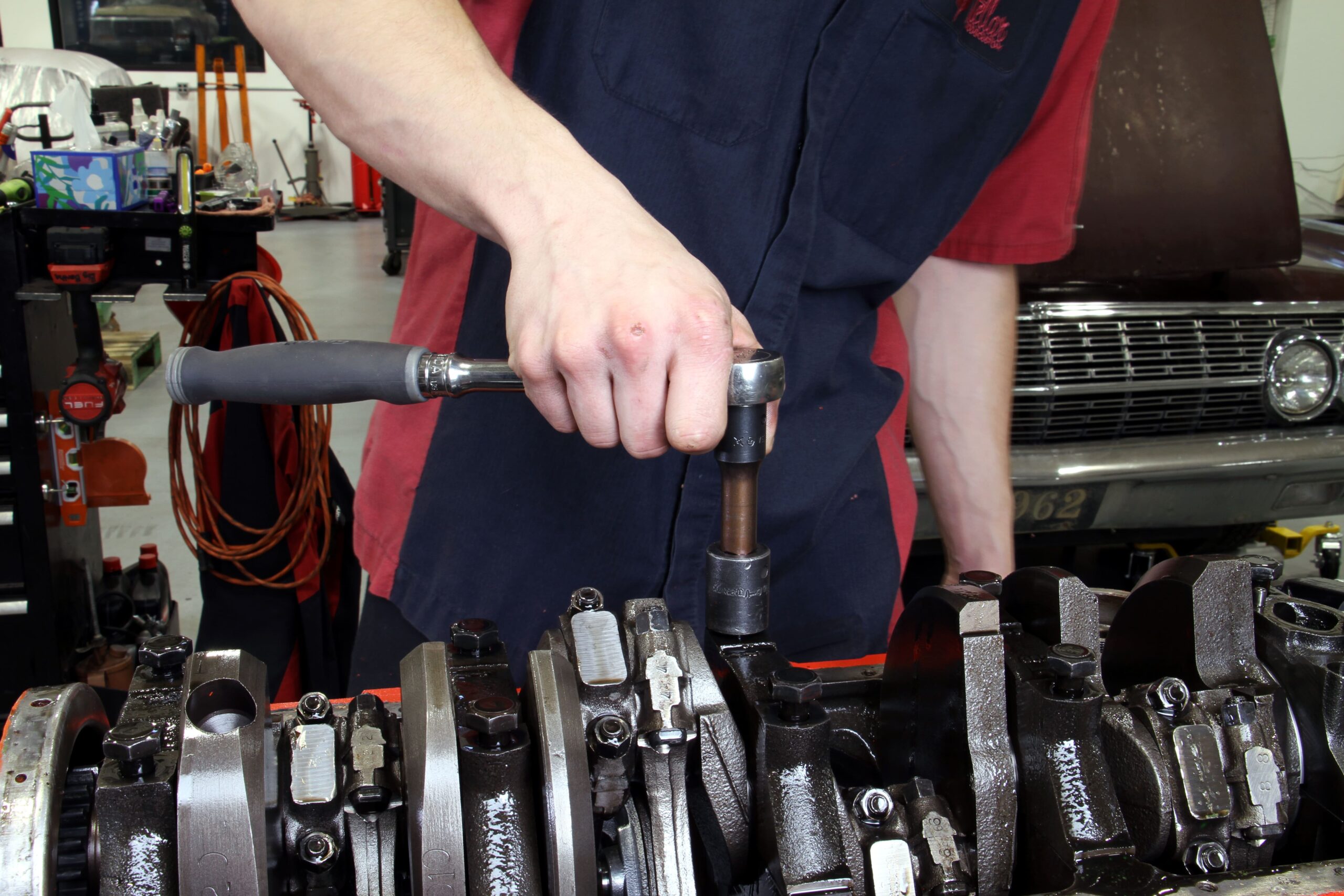
Access varies among different engine families, and while it was possible to remove the camshaft without also removing the crankshaft from this big-block, it was ultimately easier in this case to take out the crank.
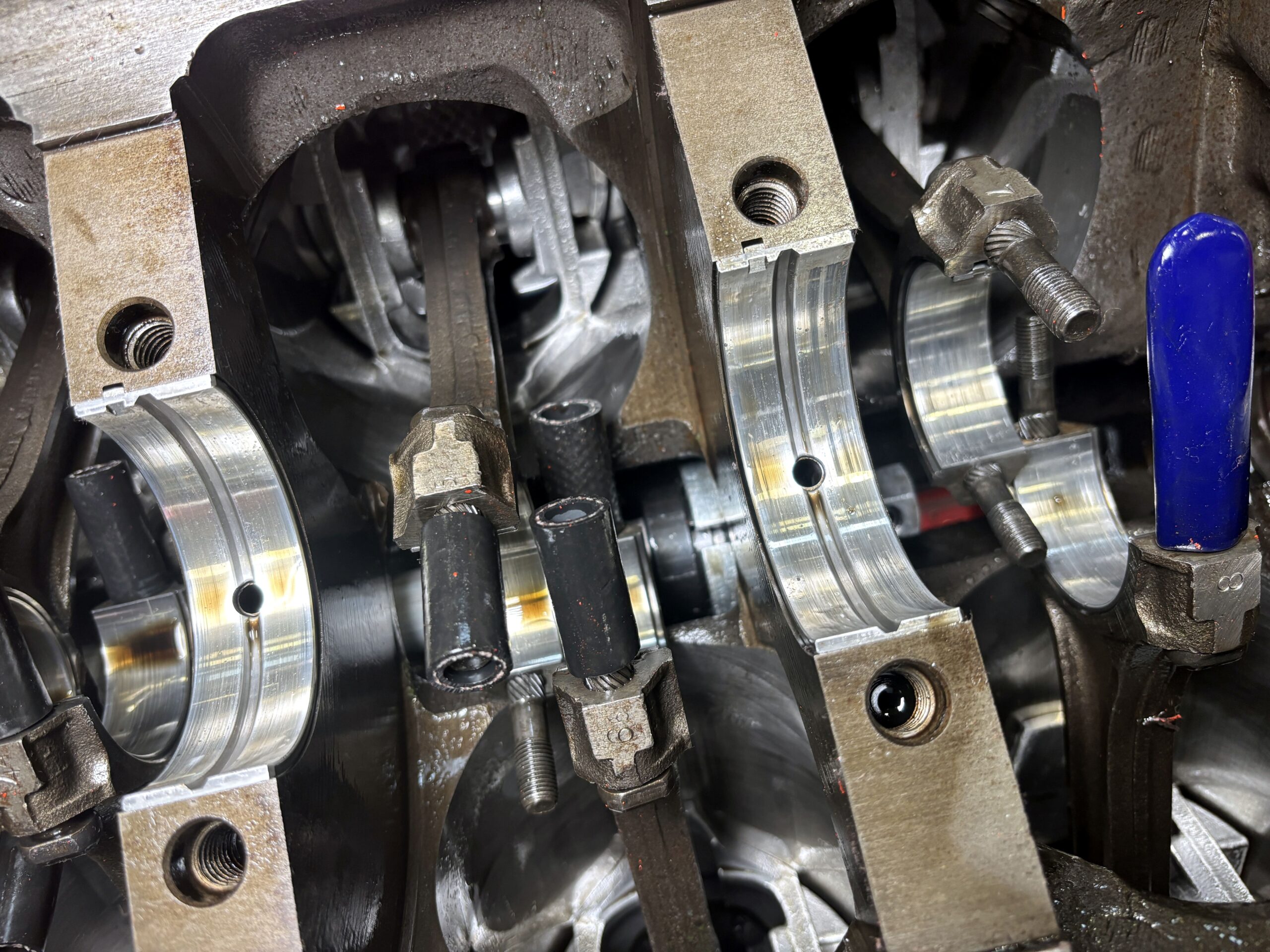
Leaving the rod-and-piston assemblies in place saved time, but care was taken to protect the rod ends. Snipping off and slipping on a few lengths of fuel hose did the trick.
There are seemingly countless options for camshaft upgrades, and for this essentially stock combination, Comp Cams’ kit (PN K11-413-8) was selected. It included an Xtreme Energy 212/218 hydraulic roller cam, along with lifters, pushrods, valvesprings, a timing set, and more.
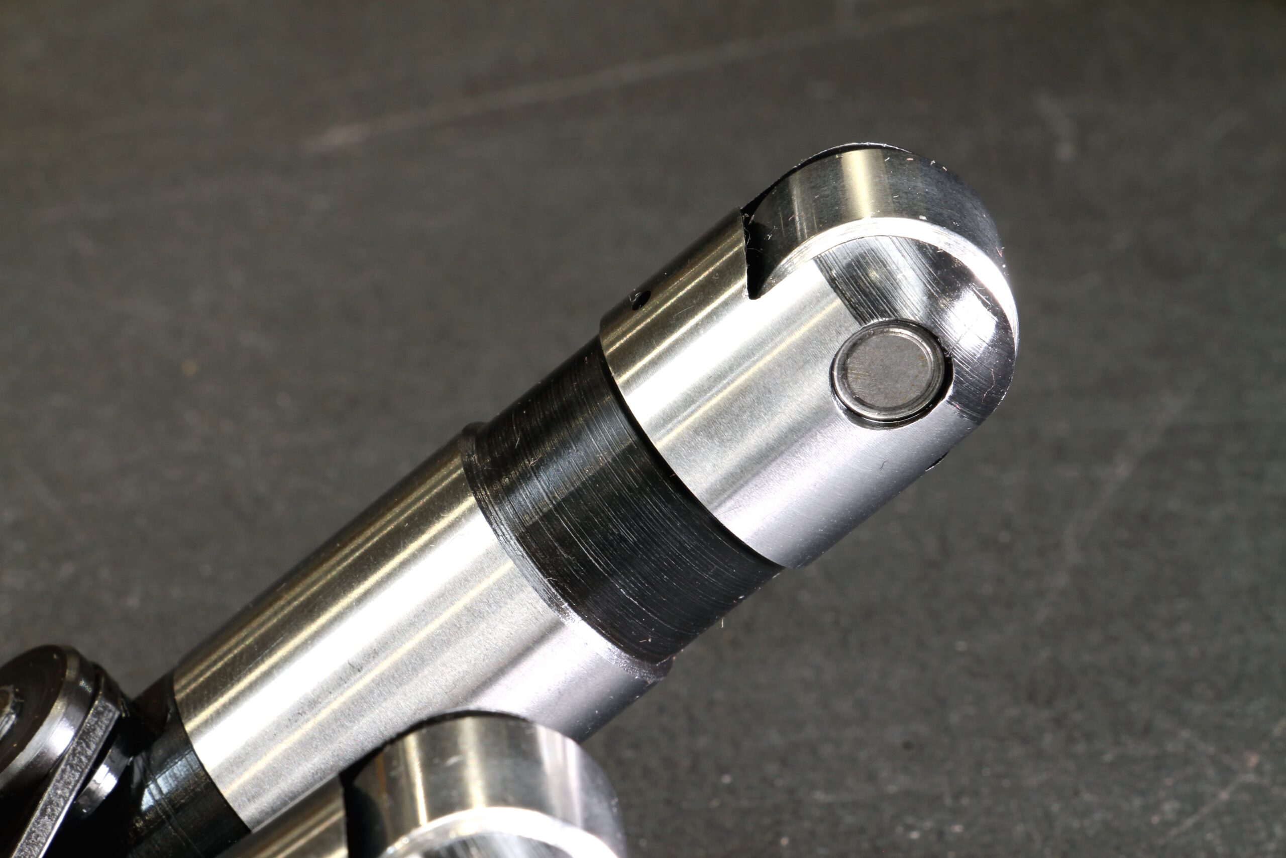
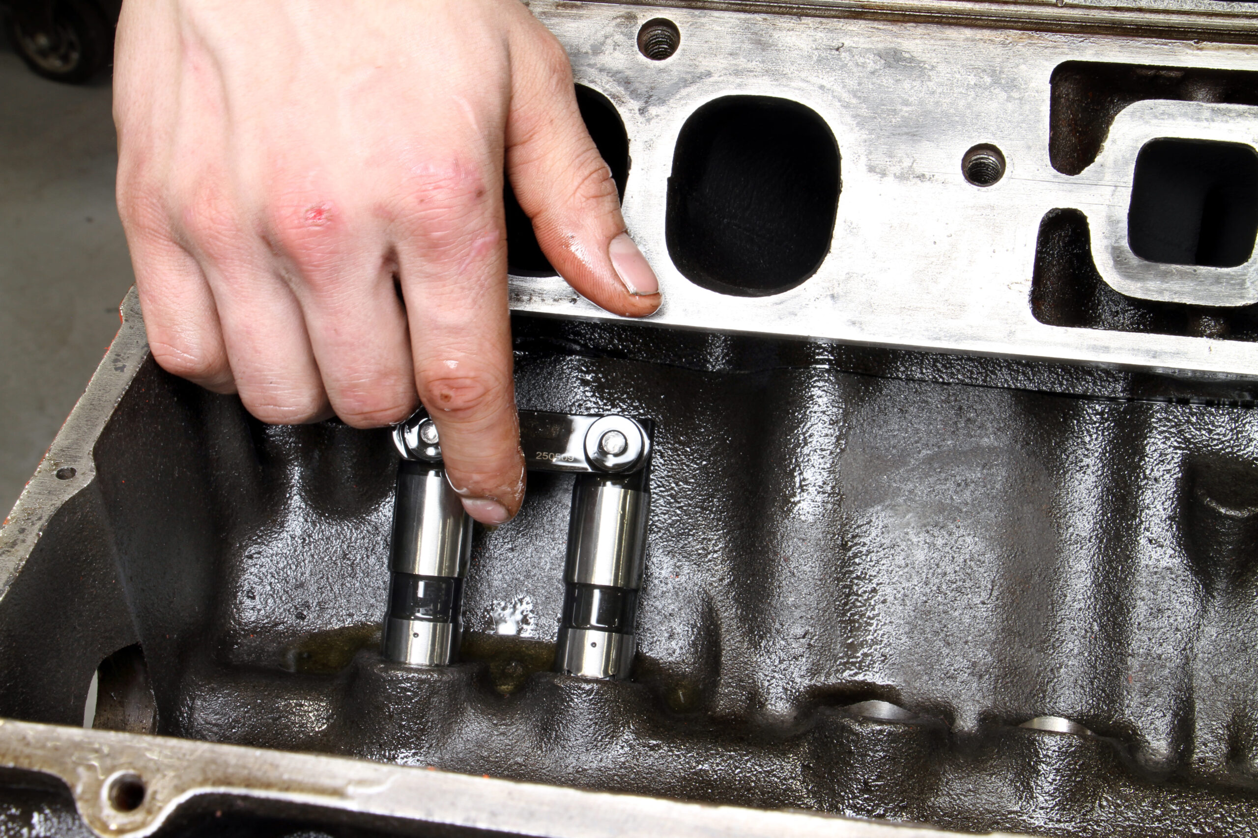
Roller lifters offer less friction, require less maintenance, and last longer. For this project, the kit included Comp Cams Evolution lifters with link bars (PN 85401-16).
Also included in the kit was a set of COMP’s single-coil valvesprings (PN 26911-16). Specs include a 1.85-inch installed height, a spring rate of 410 lb-in, and a 387-pound open load at 1.20 inches.
The cam bearings didn’t look bad after removing the flat-tappet camshaft, but for about $40, replacement was cheap insurance.
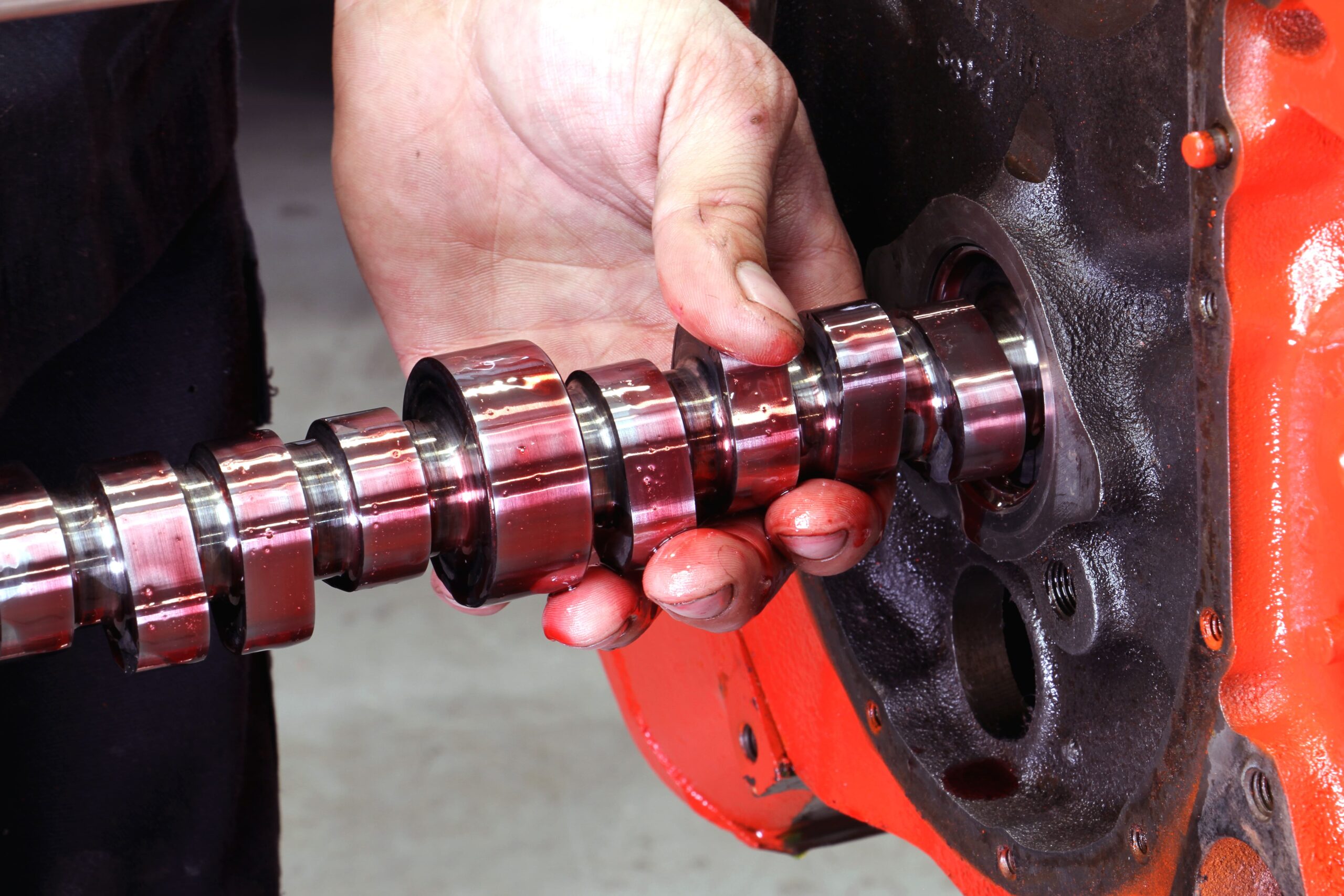
The new roller camshaft is installed. It’s essential to use a dedicated camshaft and lifter assembly lube, along with a little heavy-weight oil on the journals.
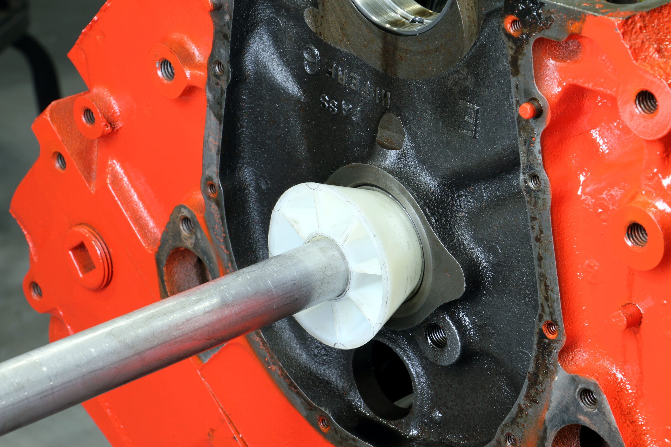
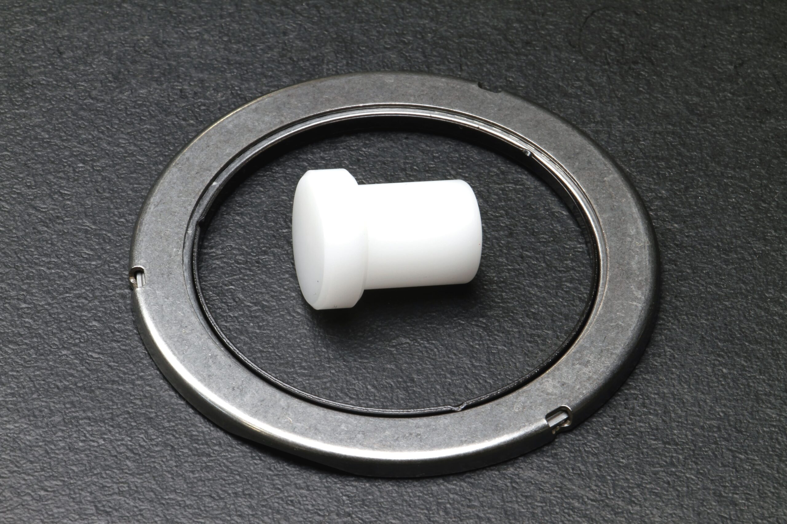
For classic Chevy engines and some others, a roller camshaft needs a thrust button to control forward and backward movement of the camshaft. It isn’t necessary on a flat-tappet design because of the tapered lobes, but the flat surface of the roller tappet allows the camshaft to shift forward and back. This button was included with the cam kit.
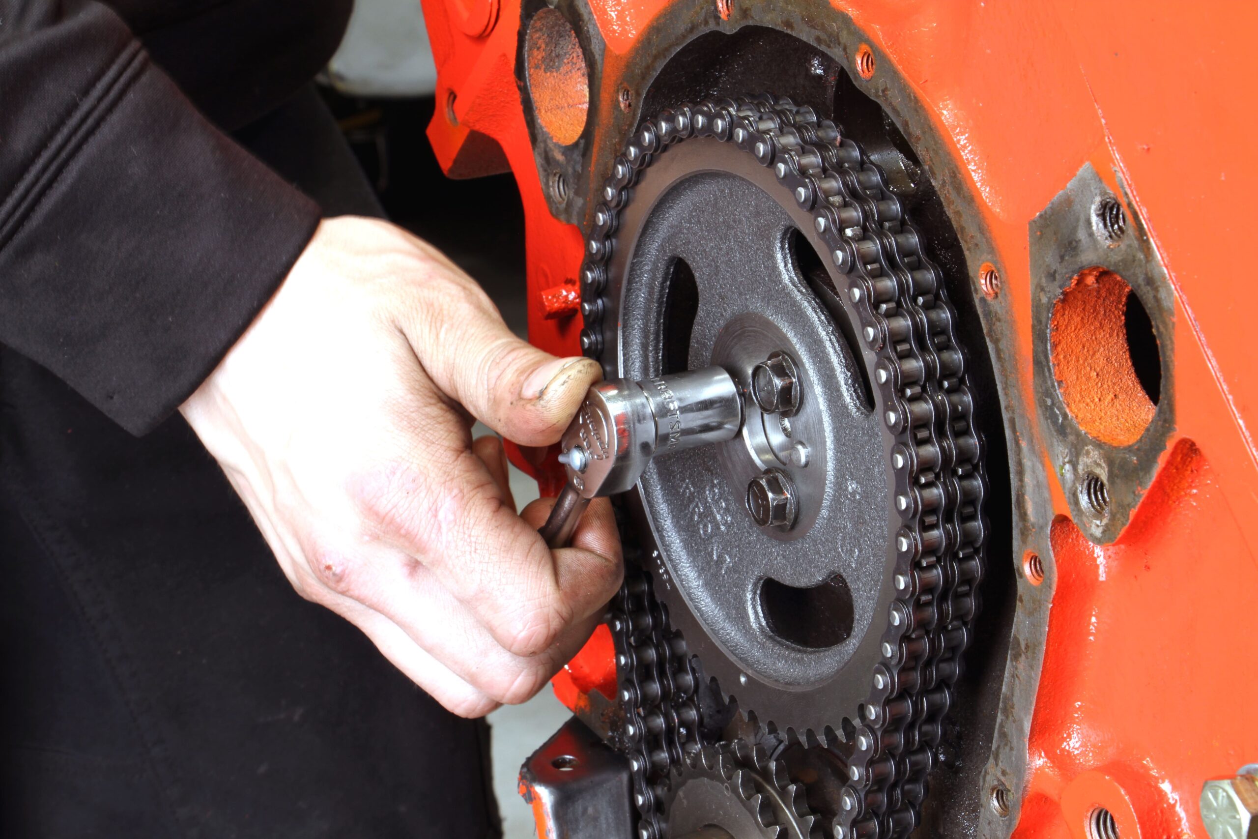
With the cam button in place, the new timing set is installed. The alignment of the timing marks does not always indicate Top Dead Center (TDC) of cylinder 1 on the compression stroke—especially on Chevy engines like this big-block. That makes it crucial to check and follow the installation guidelines carefully.
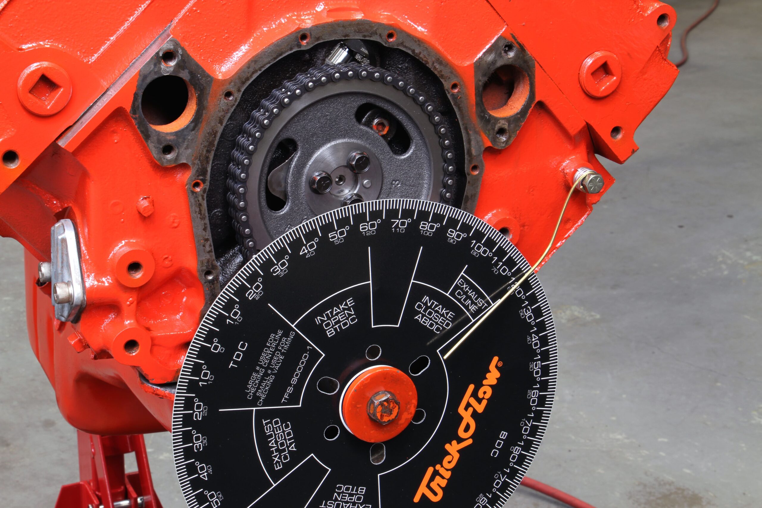
Following the directions is perhaps most important when it comes to degreeing the camshaft—a topic suitable for a standalone story. More than optimizing performance, this crucial part of the process helps ensure proper piston-to-valve clearance.
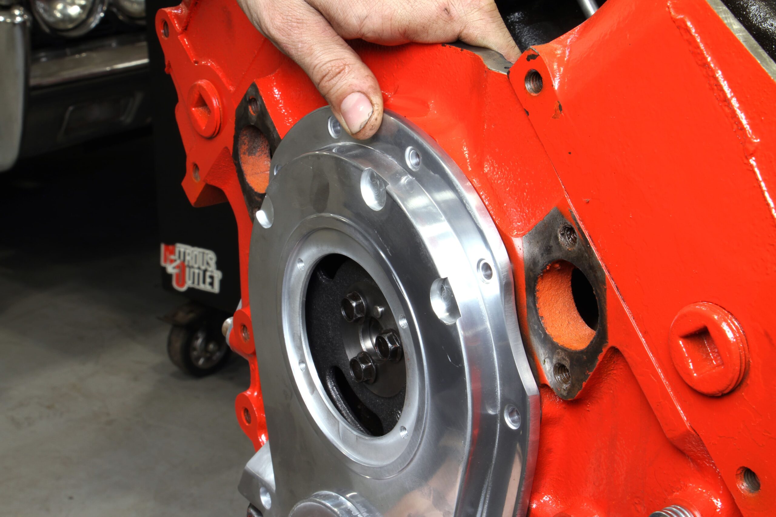
A double-row timing chain usually fits under a stock timing cover, but due to the extra width of the chain and the cam button, Stellar installed a stiffer, deeper cover to ensure proper clearance.
Hydraulic roller lifters, like those in the Comp Cams kit, have link bars that connect the intake and exhaust lifters. Before installing, it’s a good idea to hone the lifter bores to ensure they have clean, smooth surfaces.
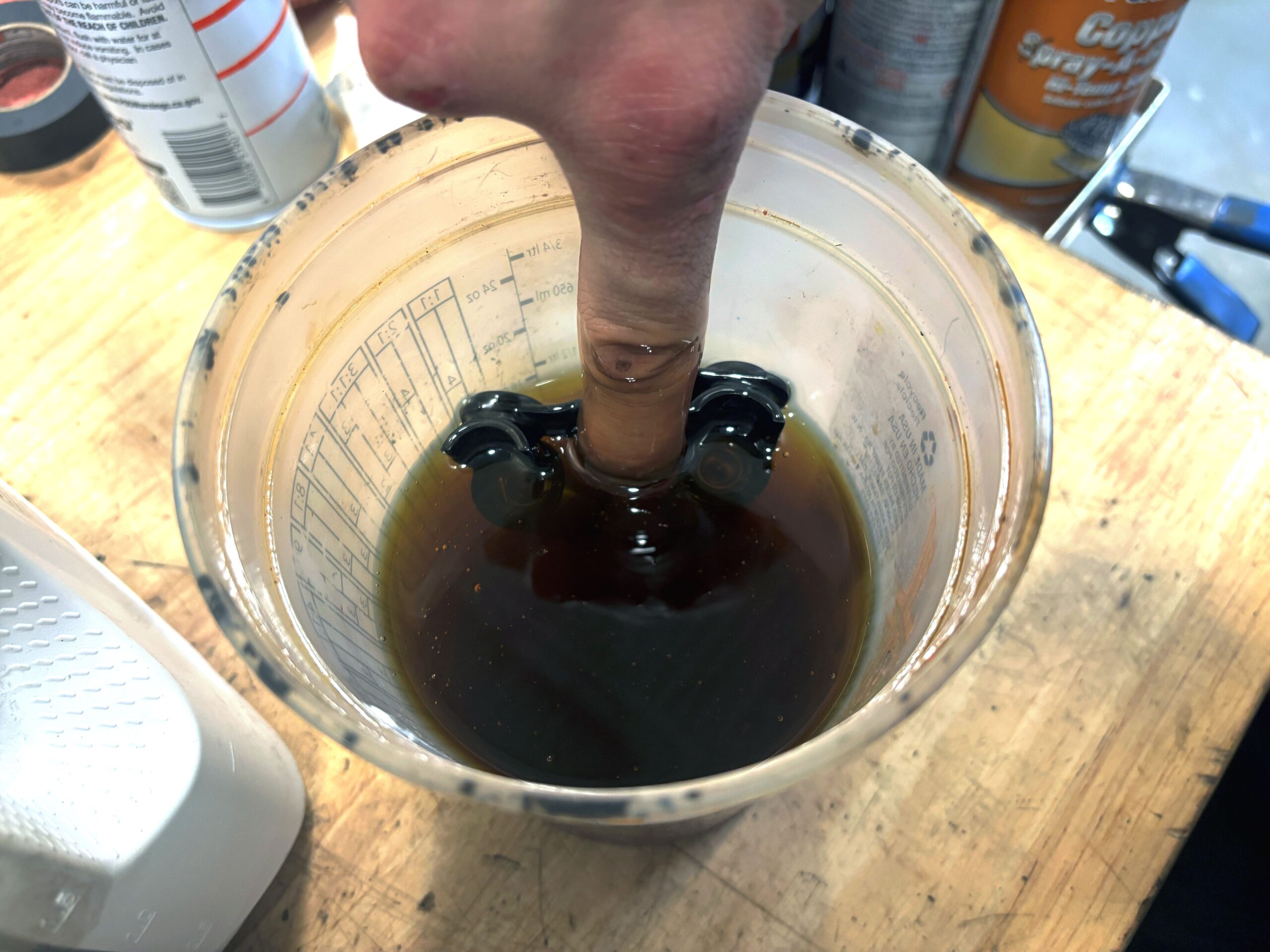
Opinions differ on whether to soak hydraulic lifters in oil before installation, but Comp Cams recommends cleaning the lifters with mineral spirits first then pre-soaking them in oil to ensure bearing saturation. The pre-soak may not be strictly necessary, but it helps lubricate the outer surfaces and promotes a quieter engine start.
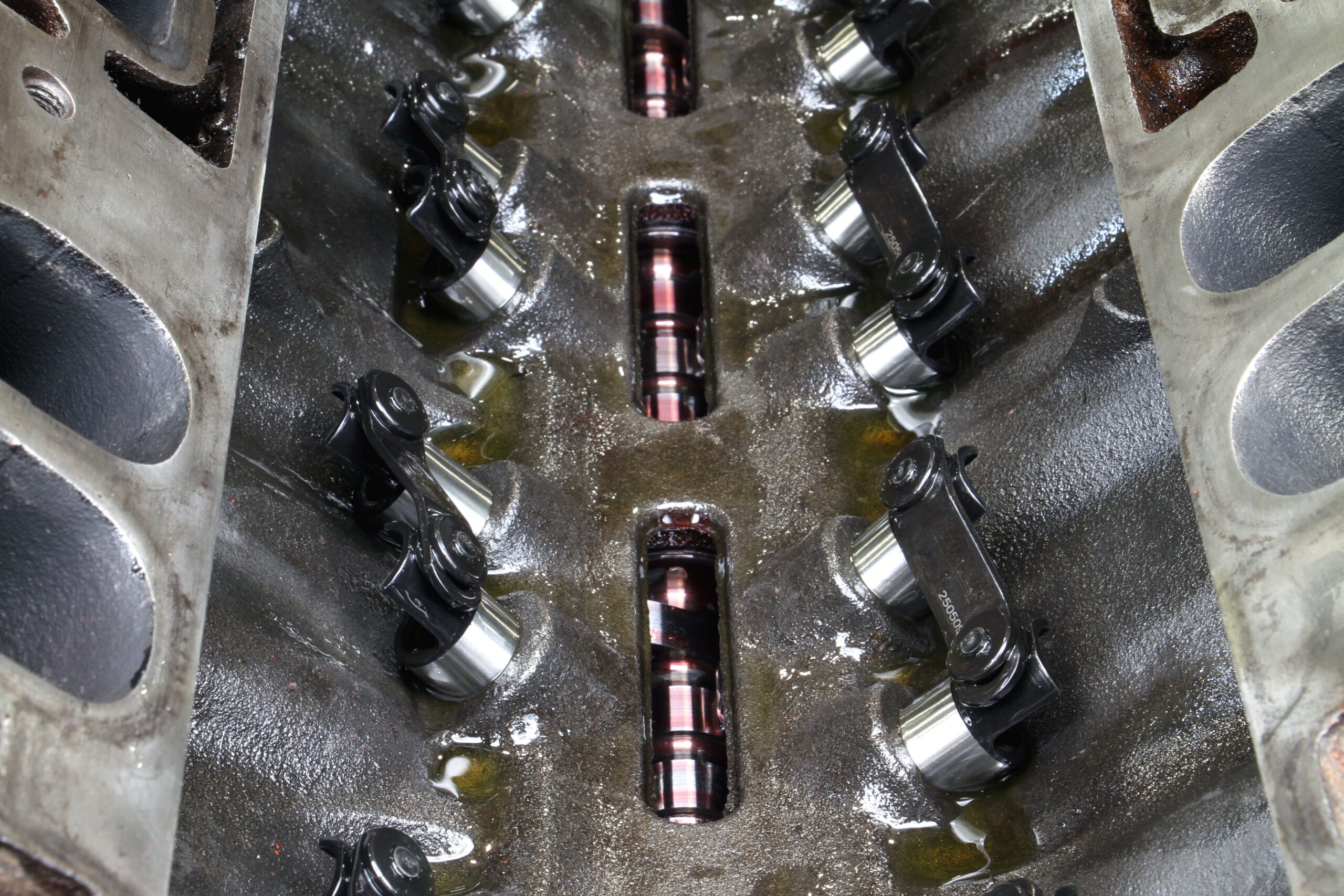
Here, all the lifters have been installed, and the new camshaft is visible through the oil drain holes in the block’s valley. Also, note that the lifters’ tie bars face the valley rather than the walls.
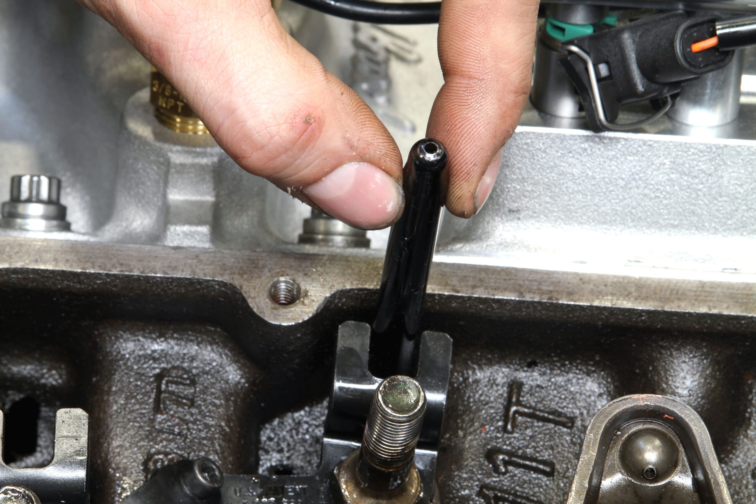
Next, come the pushrods, but that’s not necessarily as simple as it sounds. A hydraulic roller cam and its lifters will require different-length pushrods than the previous flat-tappet setup, but the actual length will also depend on prior machining work on the block and heads along with other factors.
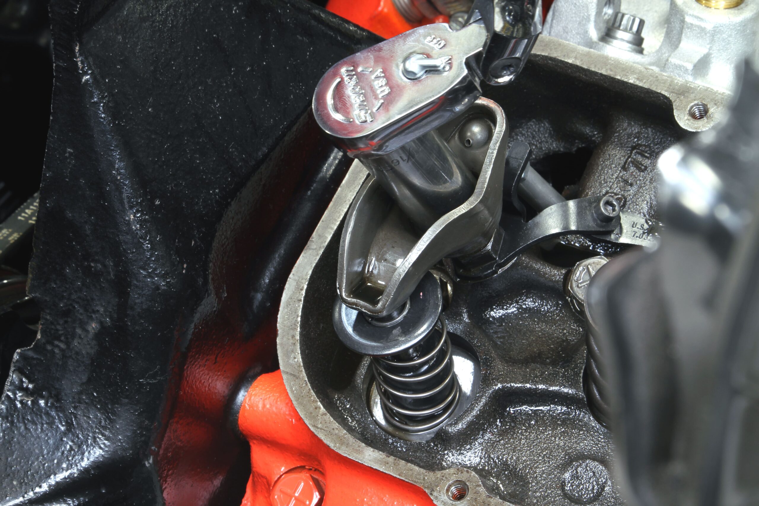
Just like with degreeing the camshaft, measuring the pushrod length involves many more steps. It includes marking the valve tip and checking the witness mark the rocker arm leaves after the valve opens and closes. Using a checking spring instead of the actual valvespring, as shown here, makes the process much easier.
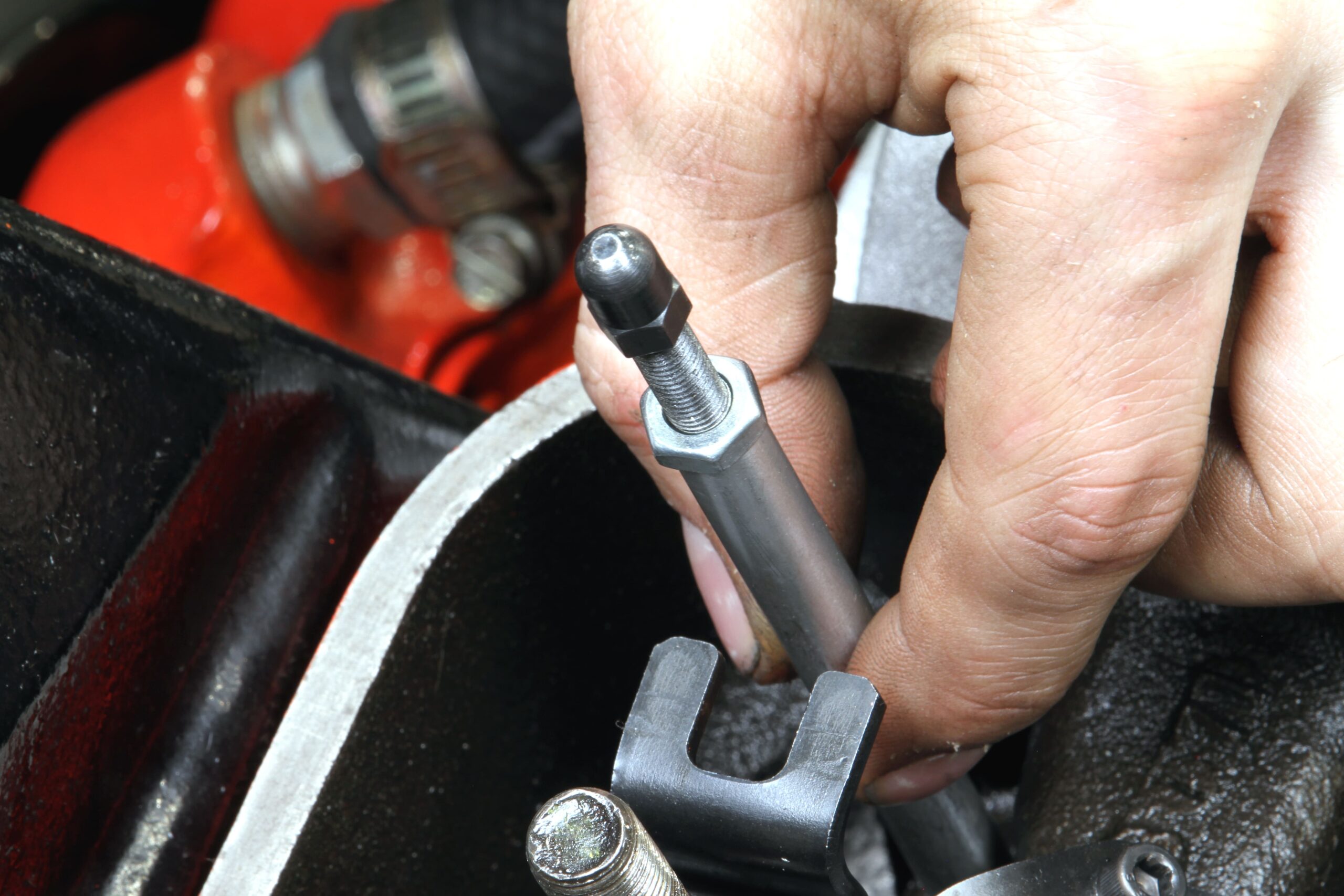
Along with the checking spring, an adjustable dummy pushrod allows the builder to lengthen or shorten it to reach the correct length based on the witness marks on the valve tip. The witness mark should be centered on the tip. A lower witness mark indicates the pushrod is too long, while a higher mark shows it’s too short.
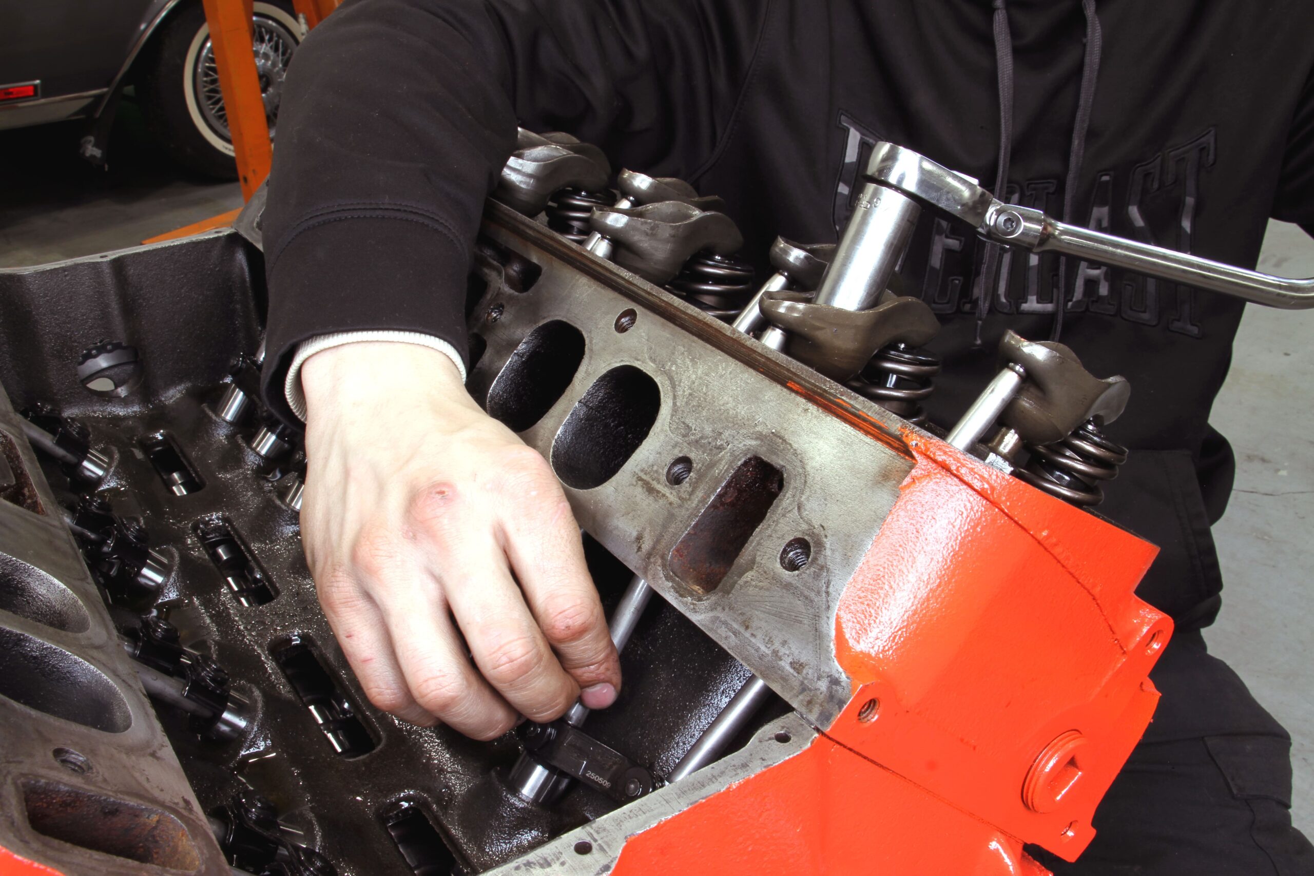
With the correct pushrods in place, it’s time to set the preload for the valvetrain to zero lash. With the spark plugs removed, begin by rotating the engine to TDC on the compression stroke. Then, tighten the rocker until spinning the pushrod with your fingers creates slight resistance. There should be no lateral movement in the pushrod at that point. If so, zero lash has been achieved, and the rocker fastener is tightened another half-turn to set the proper preload. The same procedure applies to the rest of the valves.
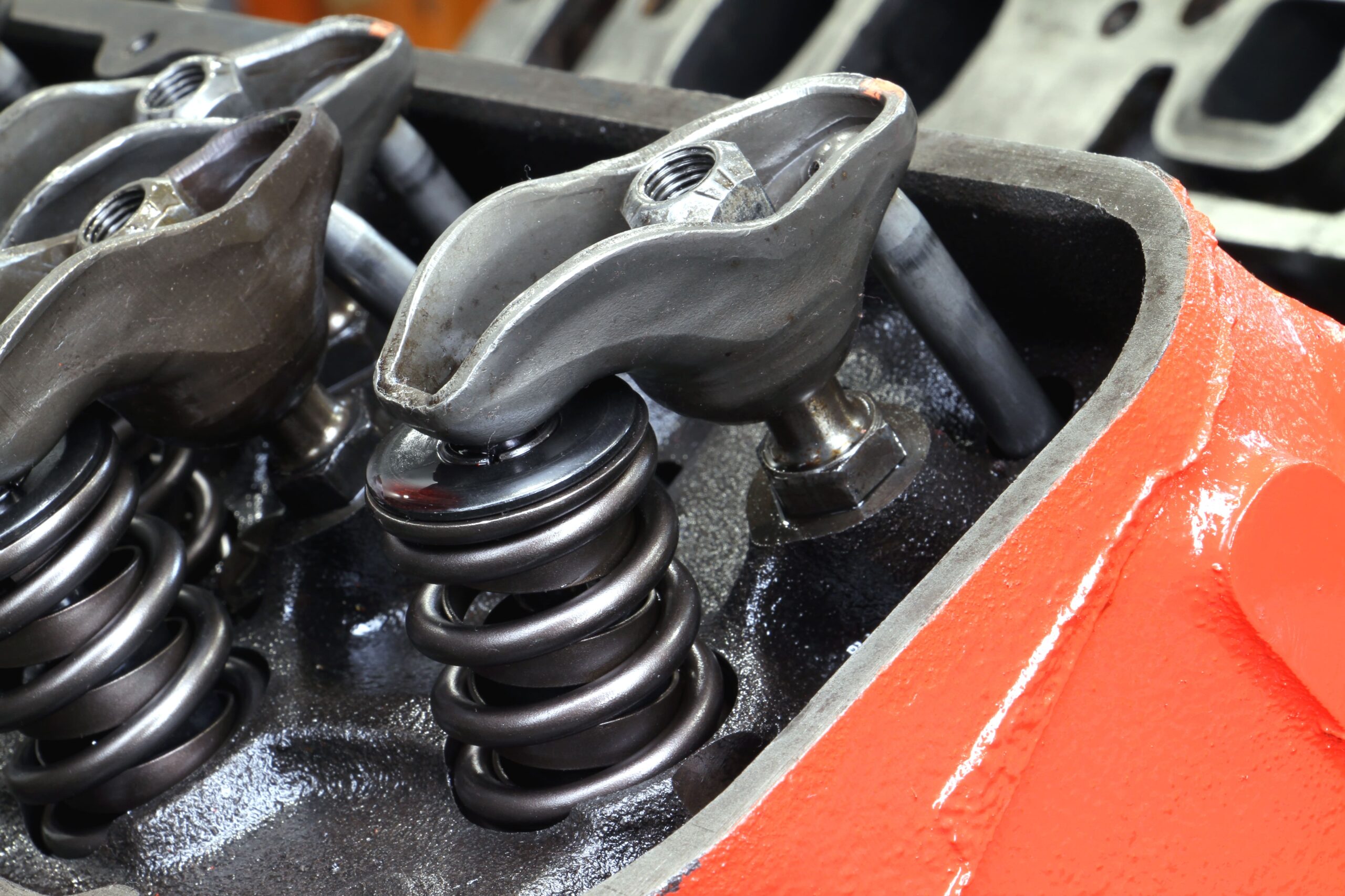
Although roller-tip rocker arms are ideal for a roller camshaft swap and can help reduce valvetrain friction, they are not essential. Standard rocker arms work just fine, and the original 1.5-ratio steel arms were reused on this engine.
Since most roller camshafts are made of billet steel rather than cast iron, their distributor gear can cause excessive wear against a standard, softer cast-iron distributor gear. Therefore, the distributor gear must be replaced with a hardened, melonite-treated steel gear, the most common and cost-effective option, like the one shown here. Bronze and composite gears are also available. Additionally, a hardened fuel pump pushrod must be used on engines equipped with a mechanical fuel pump.
We use cookies to ensure that we give you the best experience on our website. If you continue to use this site we will assume that you are happy with it.