There is a revolutionary new process for shaping sheetmetal. Once a digital file is created, a specialized machine forces a powerful stylus into a metal sheet, creating a precisely contoured metal panel. This process has very few limitations.
By Ron Covell – Photography Courtesy of Saltworks 3D Solutions
There is a new process for forming sheetmetal panels that we believe will soon gain traction in the specialty car market. This process, known as Digital Sheet Forming, utilizes a powerful computerized machine that presses a moving stylus against a sheet of metal backed by a urethane pad. The stylus starts by pushing against the outermost profile of the part and progressively moves inward with each pass, spiraling toward the center of the panel.
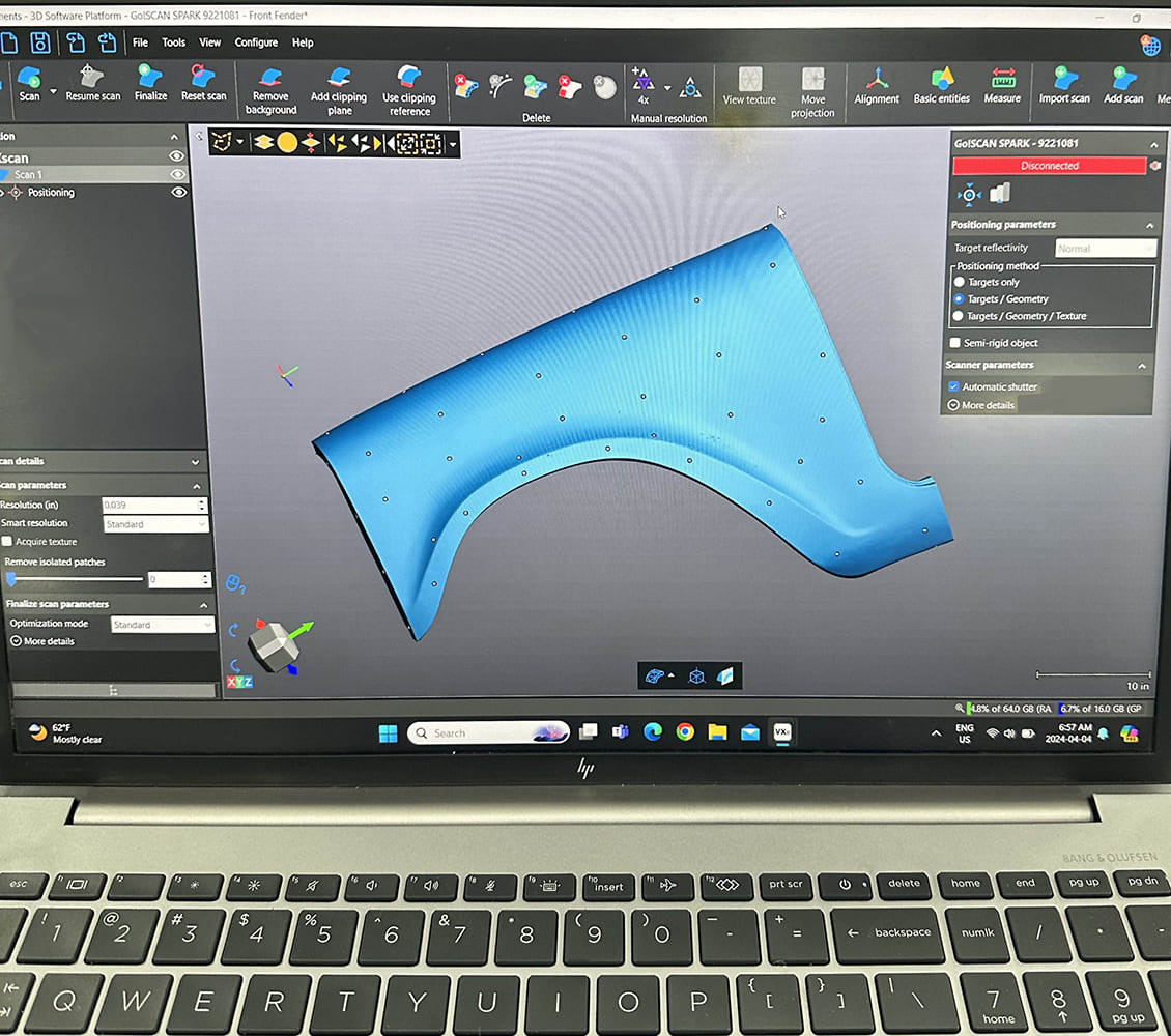
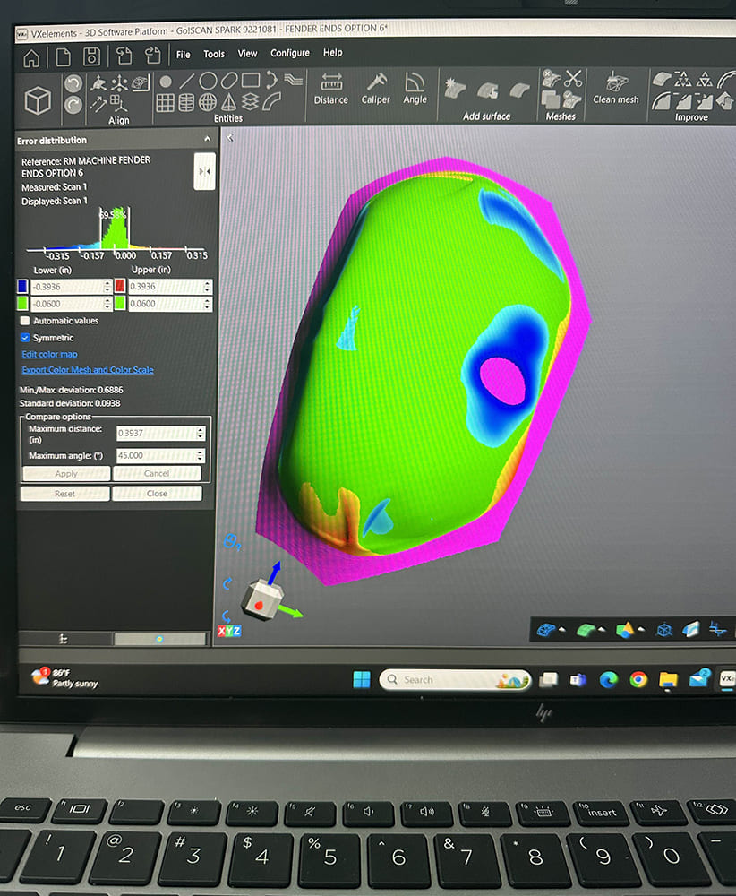
This technology has many applications. However, if you want to copy or revise an existing panel, you can begin by scanning the original.
The machine can shape various types of metal, including aluminum up to 10-gauge thickness and steel up to 14-gauge. Its maximum panel size is 47×63 inches, and it can form to a depth of 15.7 inches. Larger parts can be formed in sections and subsequently joined by welding.
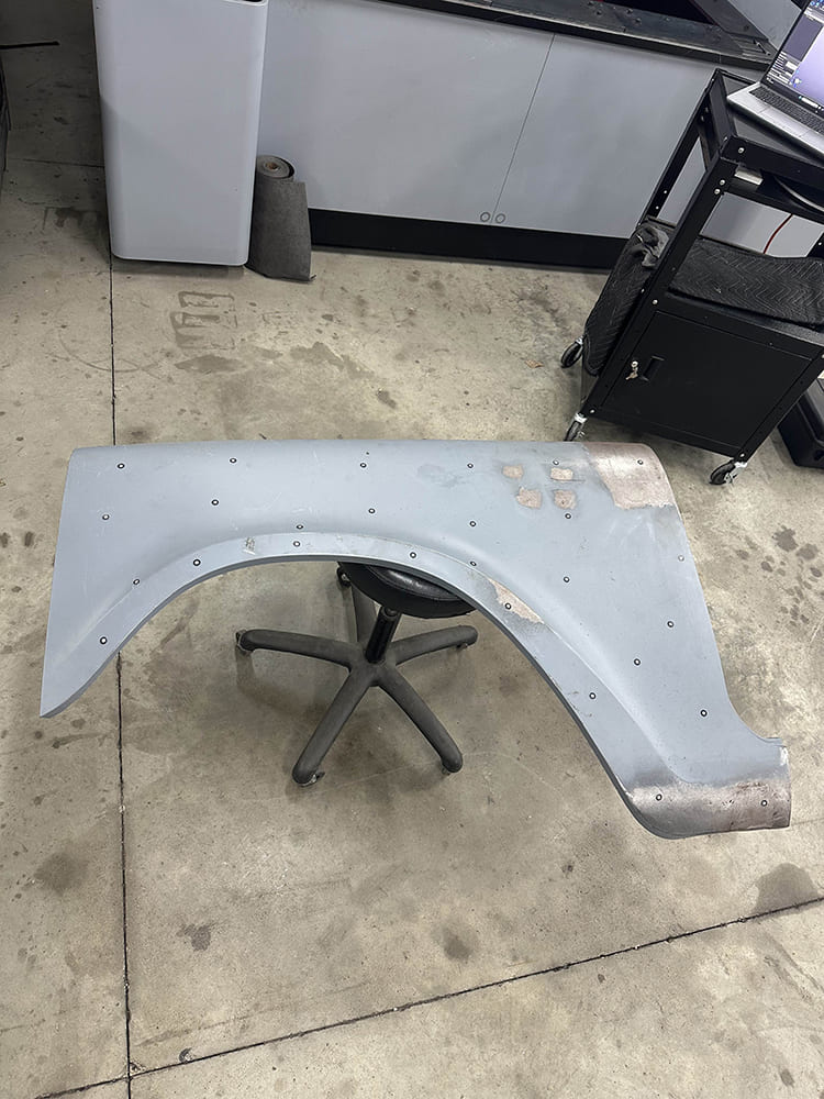
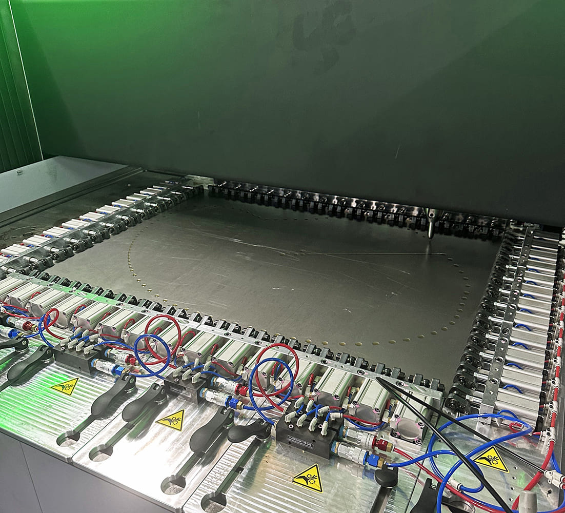
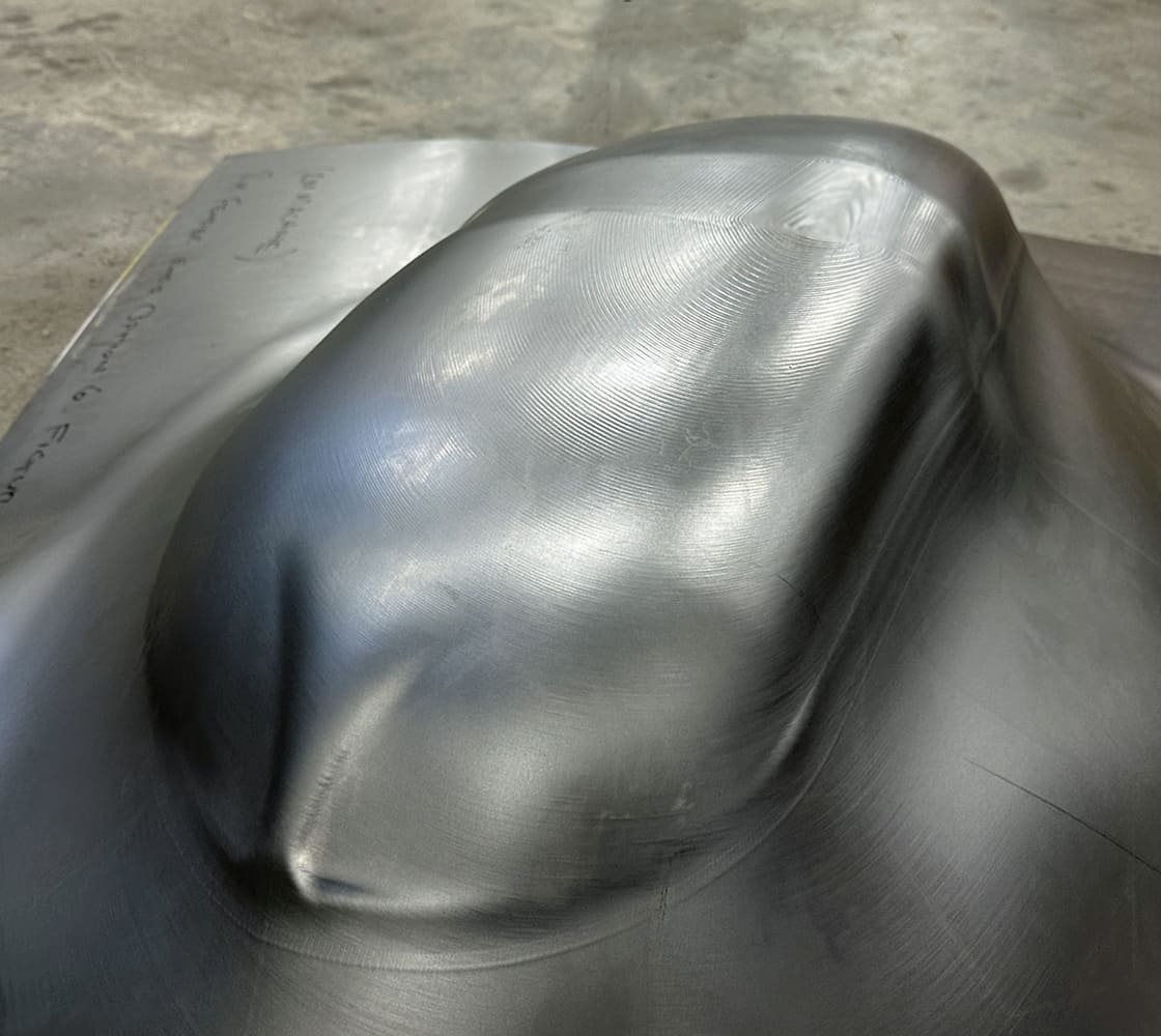
A series of small dots have been placed on this panel to aid the scanning process.
The digital file needed to operate the machine can be created using CAD software, or it’s possible to scan an existing part and either make an exact duplicate or modify the file as necessary for the specific application.
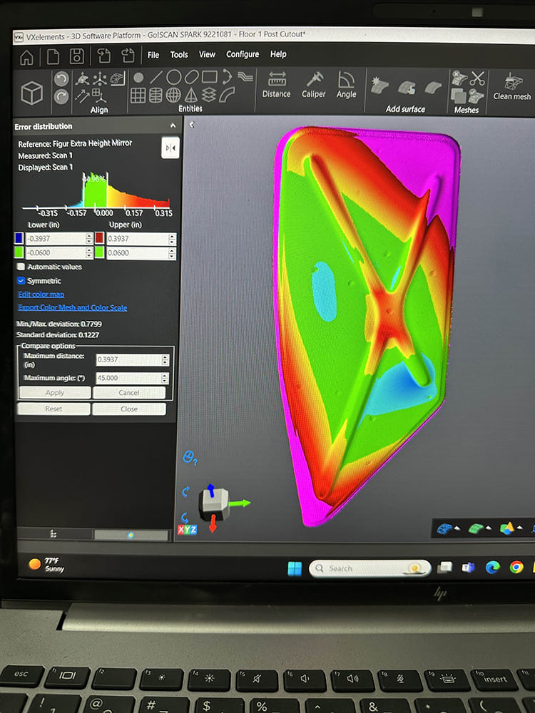
Once the original panel is scanned, it can be imported to a computer and reworked or refined using CAD software.
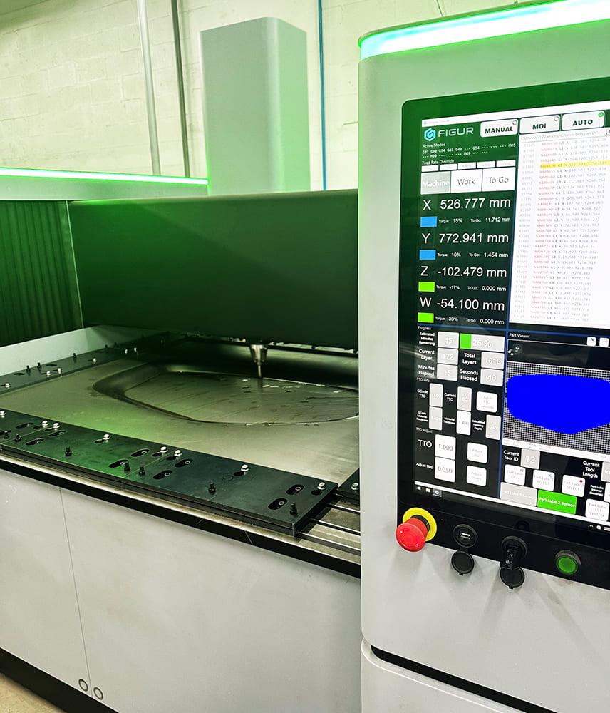
Saltworks 3D Solutions, located near Sarasota, Florida, is an early adopter of this technology within the custom auto industry. They purchased a Figur GT15 machine from Desktop Metal, based in Burlington, Massachusetts. They have been using this machine for over a year, and as they explore its capabilities it is proving to be a valuable addition to their metal shaping arsenal.
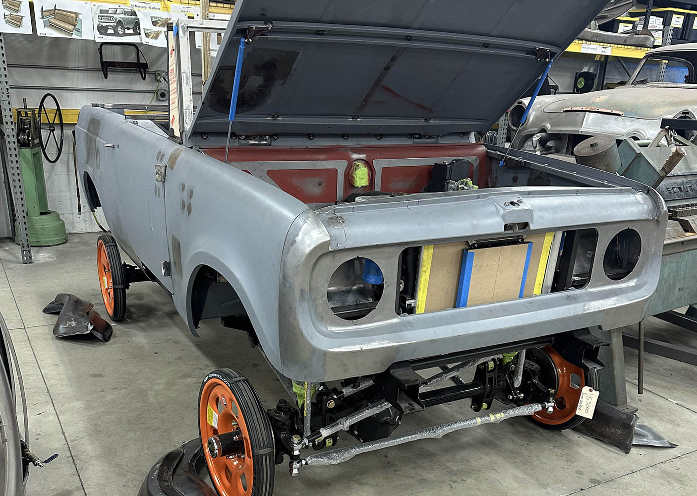
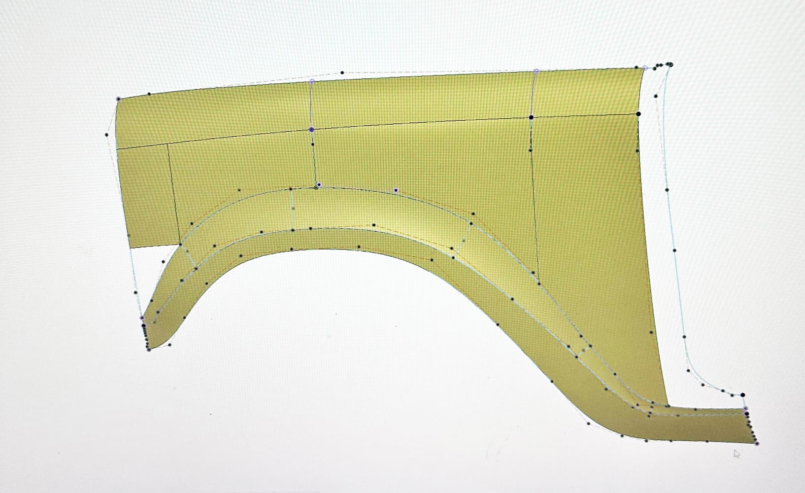
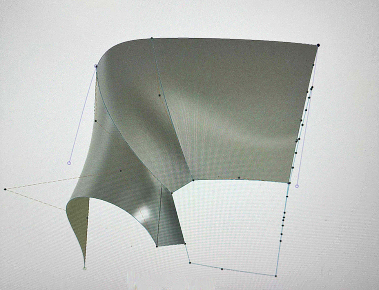
The front fender for this International Scout has been digitized, with nodes defined at key points. These nodes can be moved in any direction to reshape the part as needed.
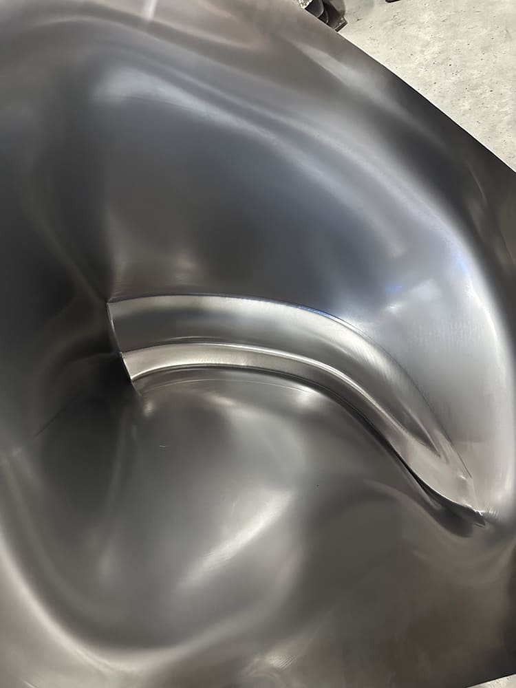
The resolution and accuracy of the shaping are excellent. The panels are often ready for use as soon as they come off the machine, although some handwork may be required in certain situations.
Once the digital file has been finalized, a flat sheet of metal is placed in the machine. The maximum sheet size is 47×63 inches, and several types of metal can be formed, including aluminum up to 10-gauge thickness and steel up to 14-gauge.
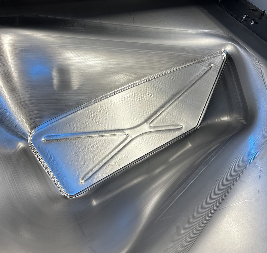
The photos showcase several parts being produced in a variety of shapes. Since the machine’s forming envelope is quite large, it often makes sense to form multiple parts during each operation. Generally, a considerable amount of metal is needed to support the shape being created, and any excess is trimmed away after the forming process is complete.
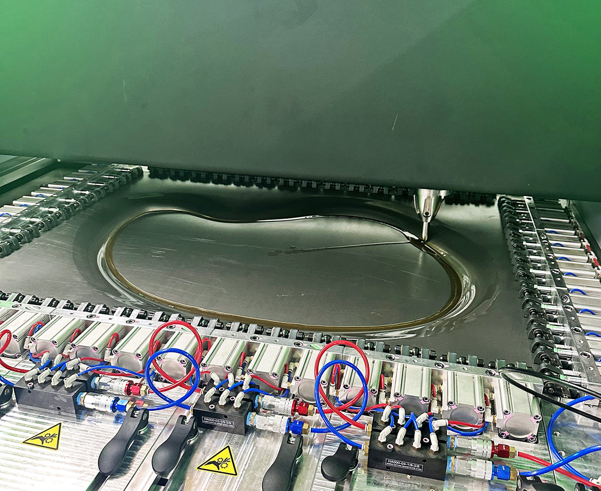
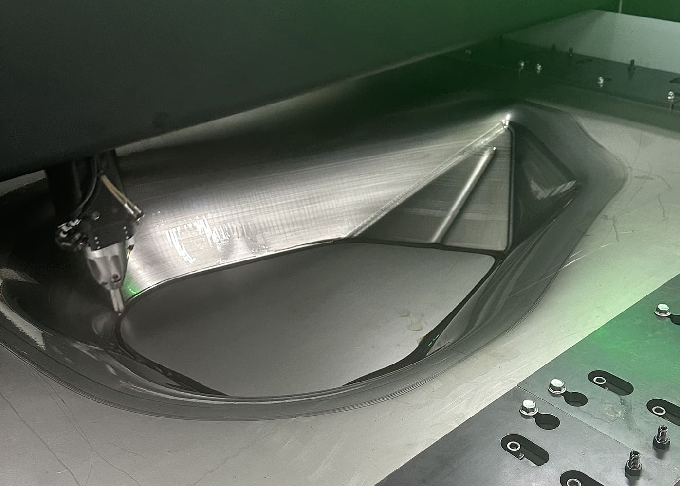
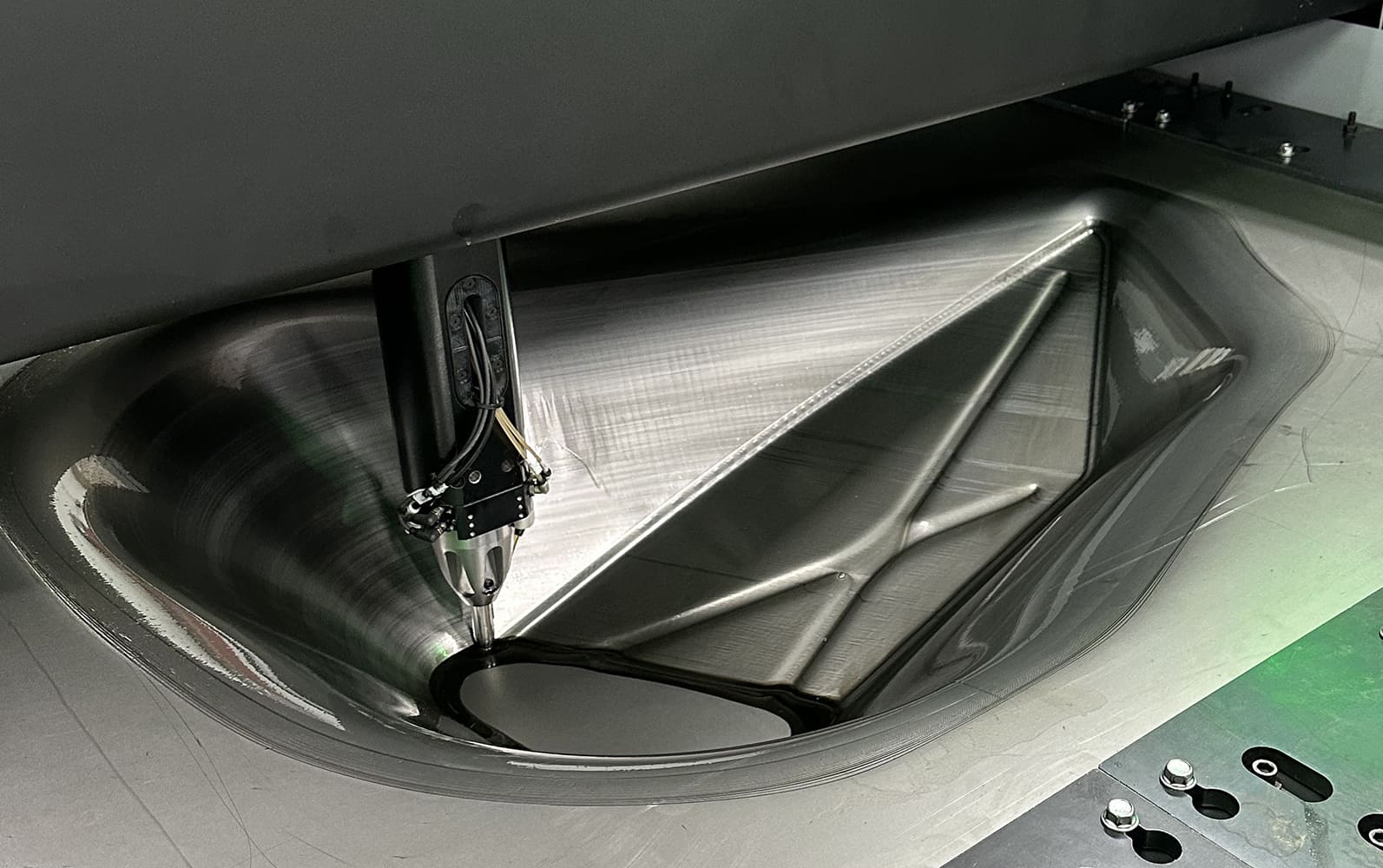
Shaping begins at the perimeter of the part, making concentric passes that go deeper while moving toward the center.
Due to the cost, not many shops will likely purchase these machines, but you can contact Saltworks 3D Solutions for a quote on any panels you may need. –MR
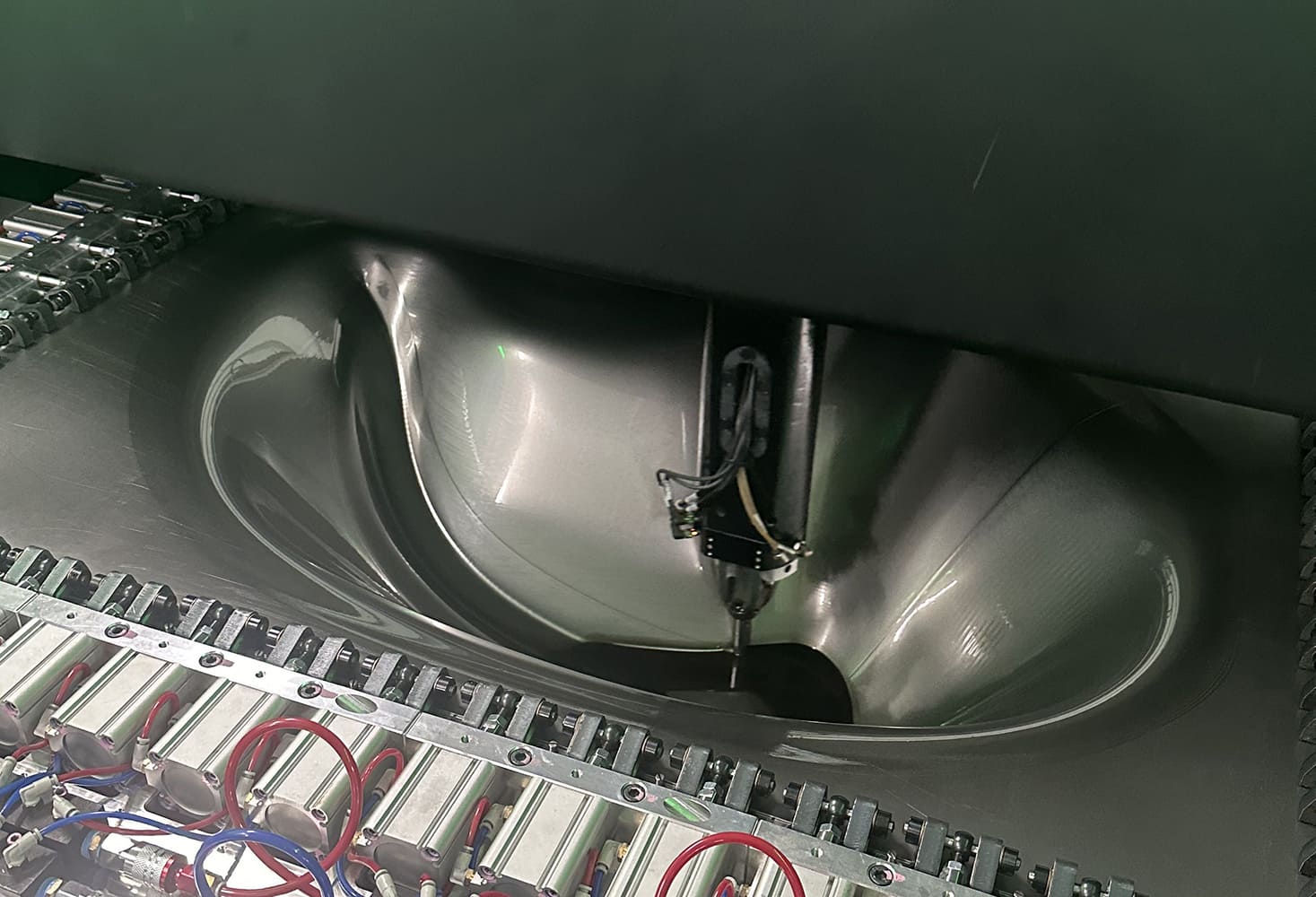
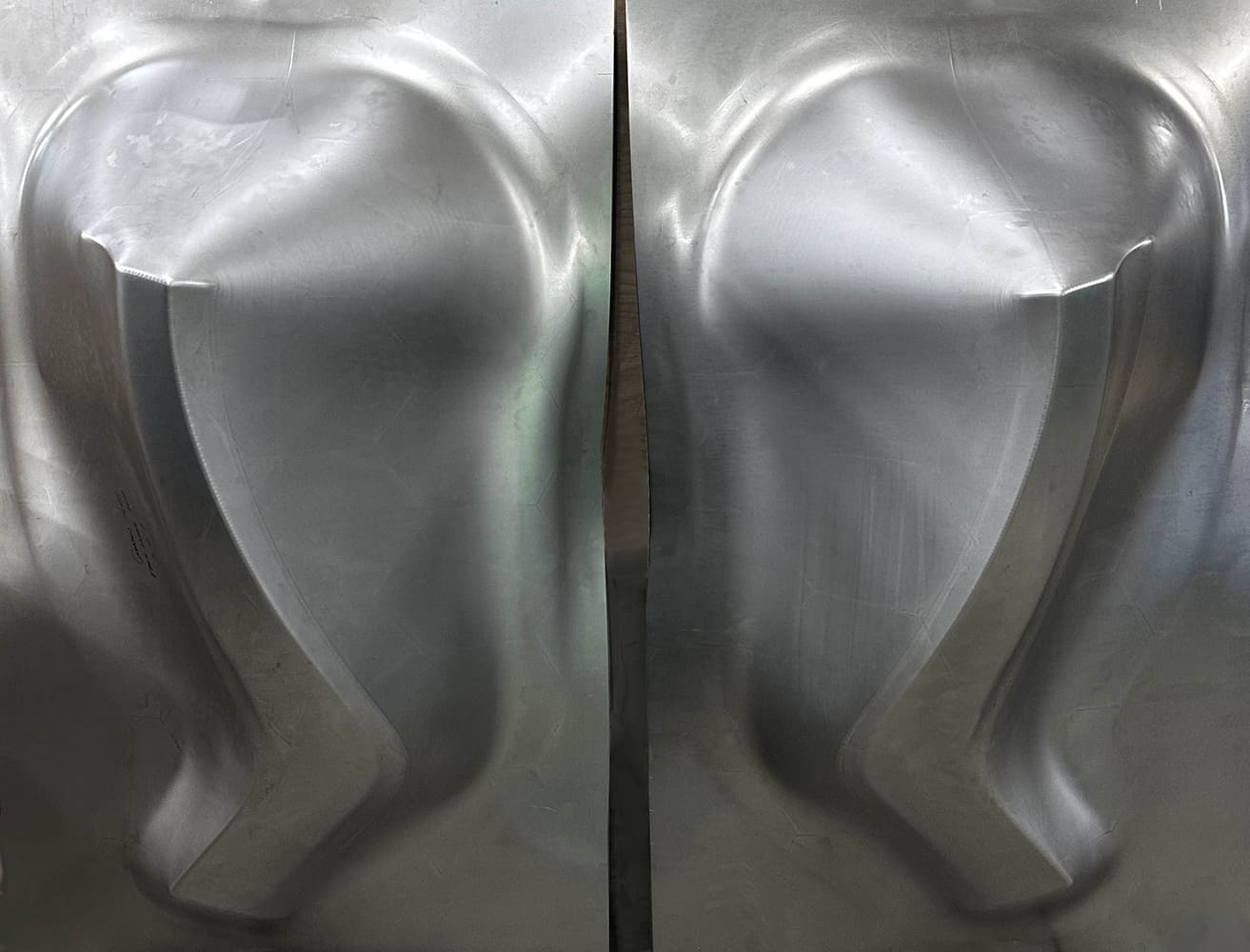
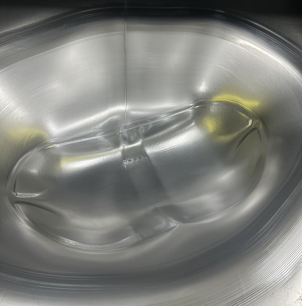
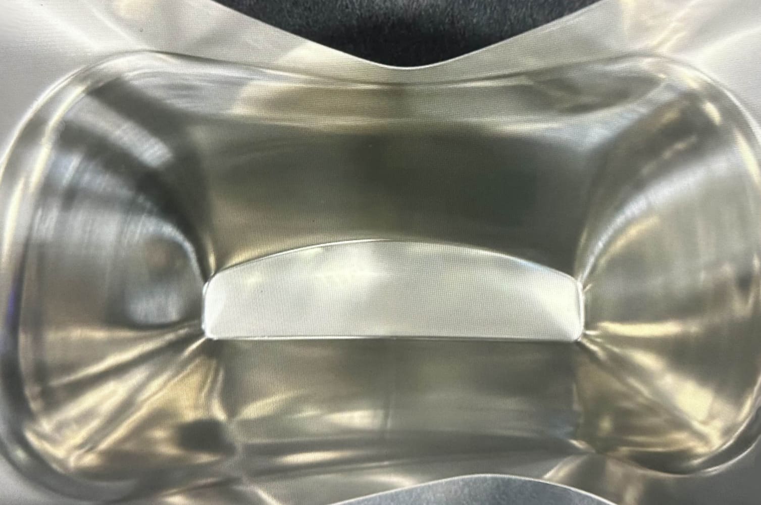
The part being created is a modified wheelwell arch for the Scout fender. After approximately 45 minutes of work, it is approaching full depth.Here’s the interior of the completed section at full depth. The surface finish is outstanding.After creating a digital file, mirroring it when needed is straightforward. Most of the metal you see here will be trimmed away, leaving the desired components ready to be joined to the original fender.Since the cavity inside the machine is quite large, it often makes sense to form two components at once. Here, two fender tips have been joined together back-to-back. Since the cavity inside the machine is quite large, it often makes sense to form two components simultaneously. Here, two fender tips have been joined together back-to-back. Once the metal is formed, the individual parts will be removed from the supporting metal.The Figur machine starts the forming on the fender tips.Here’s a shot of the inside of the two fender tips after completing the forming. This forming took about one hour.With the panel removed from the machine, you can see where the two parts will be trimmed to separate them from the supporting metal. Shaping these parts would require a skilled individual to spend many hours using traditional metalworking techniques and equipment.The software operating on the Figur machine is highly sophisticated. It is intended to shape the parts with maximum speed while minimizing the reduction in material thickness.The panel displayed here appears simple—a flat piece of metal with some raised beads—but the software has determined that it should be optimally shaped by angling it within the machine’s cavity.The forming is approaching full depth here.The finished part is highly accurate; repeats of the same panel will be identical.Nearly any shape that can be designed in CAD can be formed with this technology.The maximum depth of a formed part is 15.7 inches and parts can be joined by welding to create panels of virtually any size.
We use cookies to ensure that we give you the best experience on our website. If you continue to use this site we will assume that you are happy with it.