Colin and Sue Radford have been around performance cars since they were old enough to drive. From driving street rods with hopped-up flatheads to drag racing a small-block Chevy-powered 1936 Ford five-window coupe, up to and including setting a G/GMR record at Bonneville, the Radfords know about all aspects of performance—and that not only means knowing how to make cars go fast but how to make them stop quickly as well. A case in point is their latest project, a 1965 Mustang fastback that will be equipped with a built FE Ford V-8 and has already been equipped with four-wheel disc brakes from Classic Performance Products (CPP).
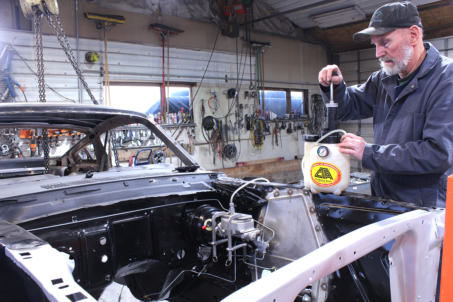
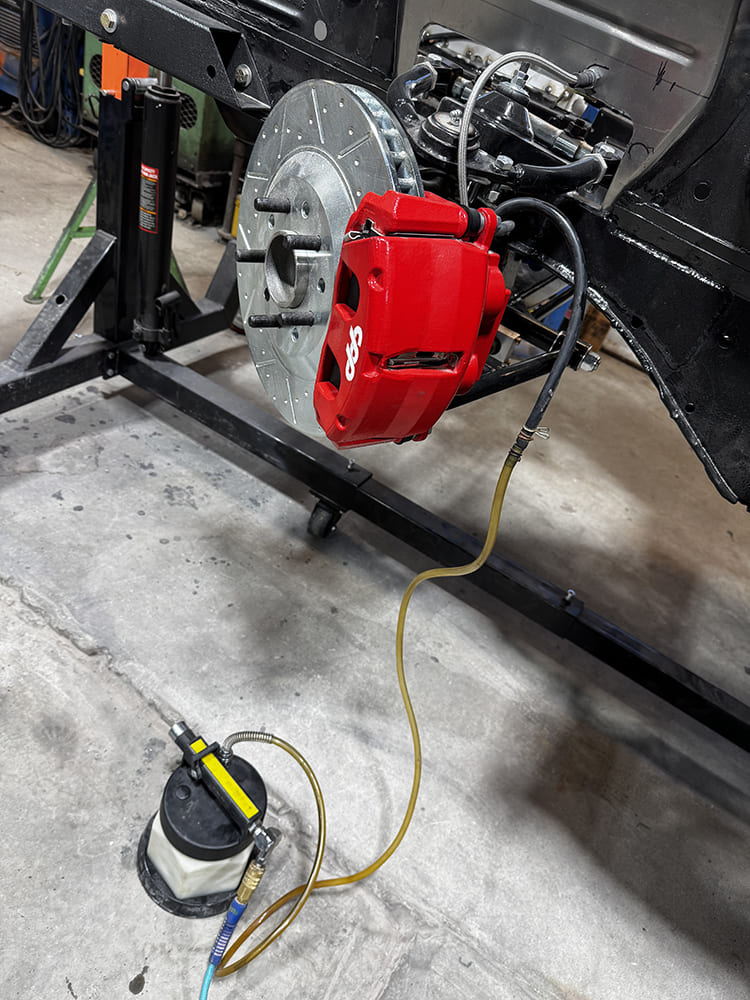
Colin Radford used a hand pump pressure bleeder to remove all the air from the newly completed brake system in his 1965 Mustang fastback.
In the Mar. ’25 issue of Modern Rodding, we covered replacing the factory drum brakes with CPP’s Big Brake Kit on both ends. Up front are Corvette-style aluminum calipers that have two 42mm pistons; in the rear are 45mm single-piston floating calipers with parking brakes. The single-reservoir “fruit jar” master cylinder was swapped for a dual-diaphragm Midnite Series vacuum booster and a dual-chamber aluminum master cylinder. (The assembly includes a combination valve that has four functions—a proportioning valve, residual check valve, metering valve, and brake warning light switch.) With all the components installed the next task to tackle in the upgrade was to plumb the chassis to make it all work.
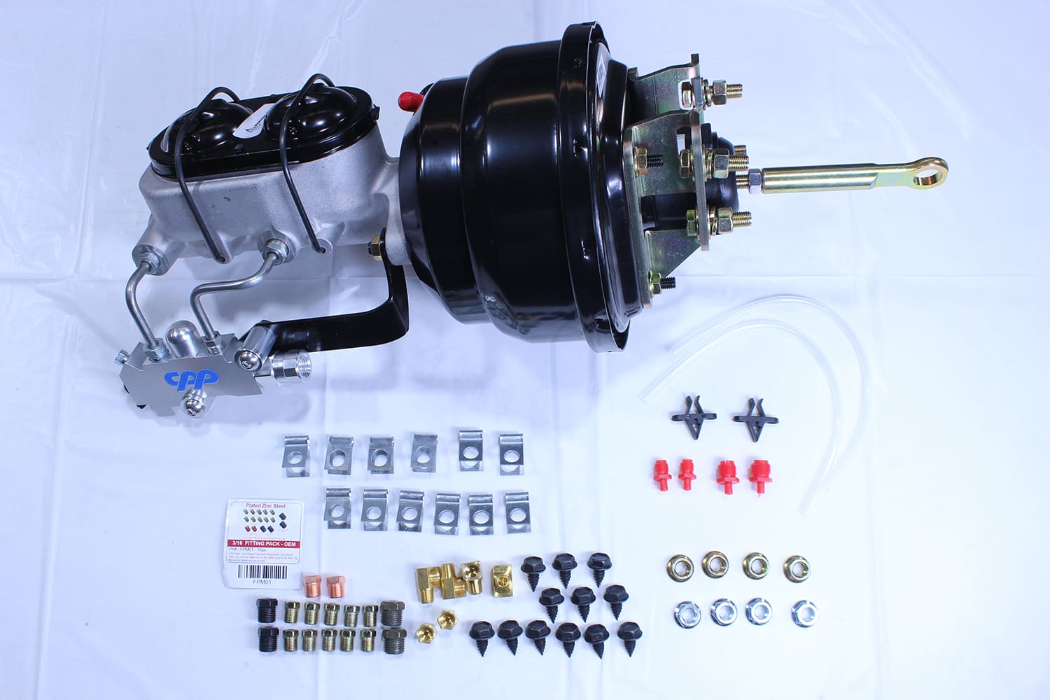
This is CPP’s Midnite master cylinder and booster assembly (PN MNS6466BB24-8D). It comes with an aluminum master cylinder and combination valve all engineered for 1964-66 Mustang models running an IFS front clip. The dual diaphragm vacuum booster increases assist for two- and four-wheel disc brake systems.
One common misconception about brake plumbing is that there is a relationship between brake line size and hydraulic pressure—there isn’t. The master cylinder establishes the pressure in a brake system; all the lines do is deliver the pressurized fluid. Brake lines are typically 3/16- or 1/4-inch diameter and, while there will be no pressure difference between the two, there will be a difference in the amount of fluid that can be delivered. The bigger tubing will carry more volume, so 1/4-inch line may be preferable when using large-volume drum brake wheel cylinders or calipers. However, for most applications 3/16-inch line is more than adequate and is preferred.
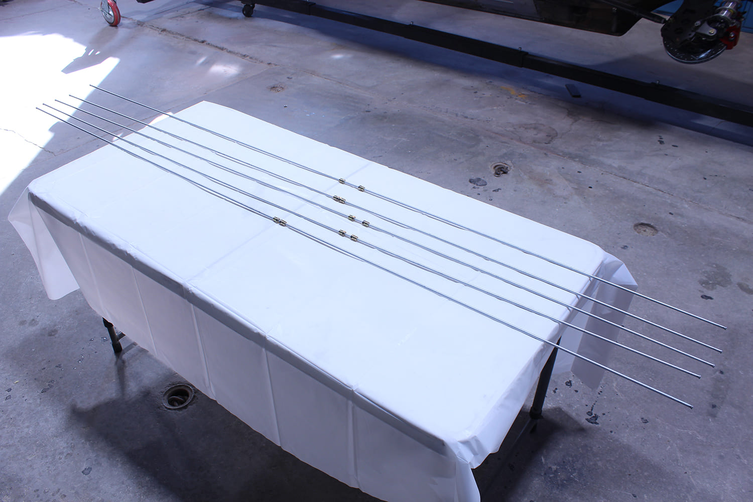
The steel brake lines come with double flares and the appropriate tubing nuts.
Regardless of the size, when it comes to selecting the type of rigid brake lines to use, there are two common choices: steel or stainless steel. Copper or aluminum should never be used, as they lack adequate bursting strength and excessively long lengths of flex line, including the braided variety, should be avoided as a spongy pedal may result. While pure copper brake lines should never be considered, there is a viable option that looks similar called NiCopp. Made from a copper/nickel alloy, NiCopp brake lines are DOT approved. This material is easy to bend, flares easily, and is corrosion resistant. However it isn’t as rigid as steel and stainless steel so more support is suggested in the form of closely spaced clamps. Regardless of the brake line material used, when plumbing a chassis, brake lines should be a minimum of 3 inches away from any significant heat sources, most notably the exhaust system.
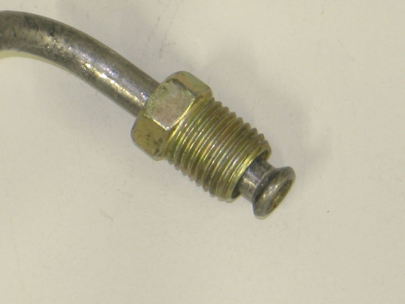
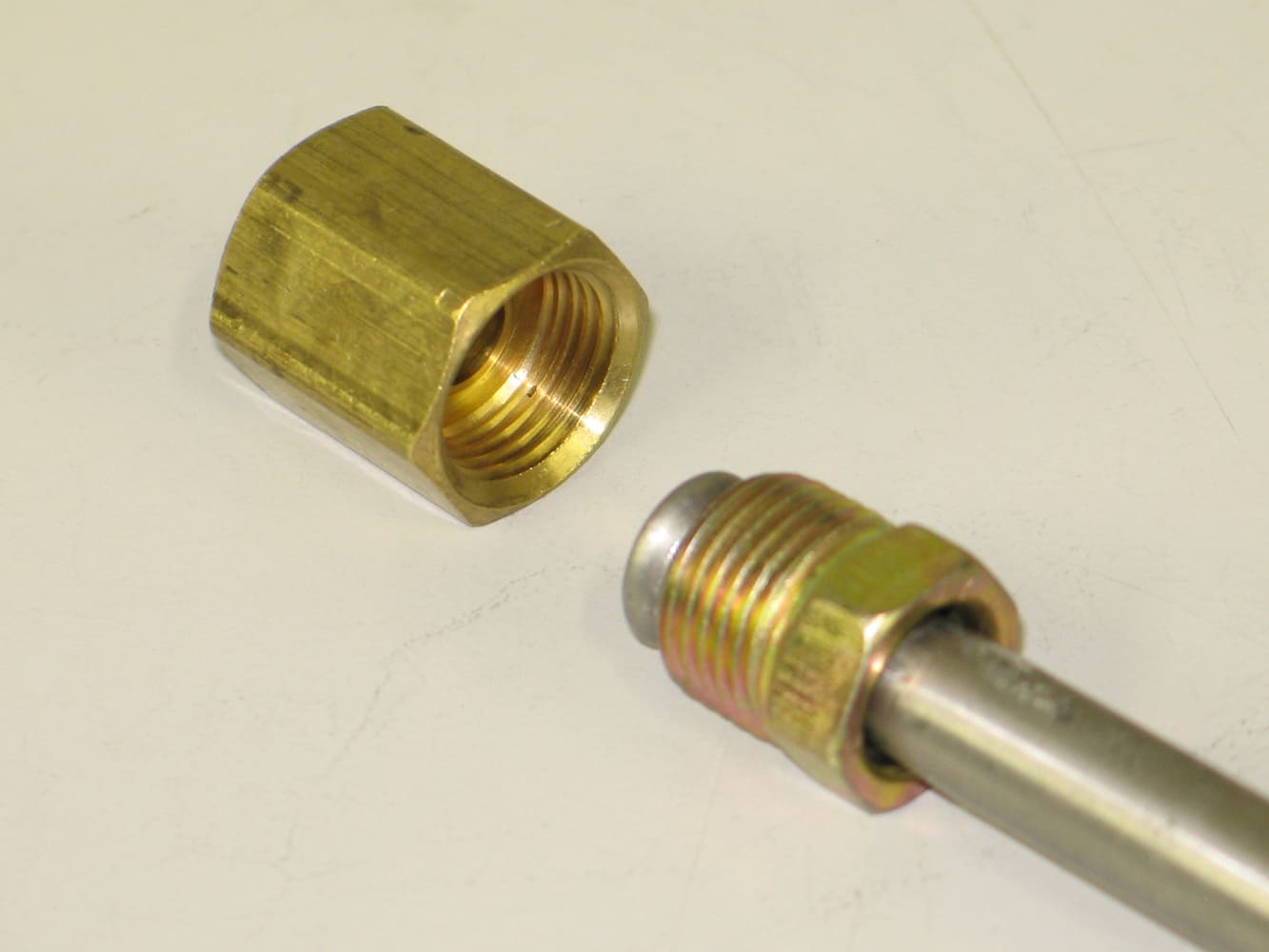
When installing custom brake lines you can count on having to flare the ends of the tubing to make necessary connections. Steel lines typically use the SAE (Society of Automotive Engineers) 45-degree double flare that fits into an inverted flare fitting. Forming these flares is a two-step process that requires the proper tool (CPP offers a variety of double flaring tools). By comparison, stainless steel lines typically use 37-degree flares and fittings—the bottom line is the two fitting types are not interchangeable.
There a variety of methods to remove air from a brake system. Radford used a bleeder that draws fluid through the system. Somewhat ironically, it’s powered by compressed air (the hose isn’t hooked up in this photo).
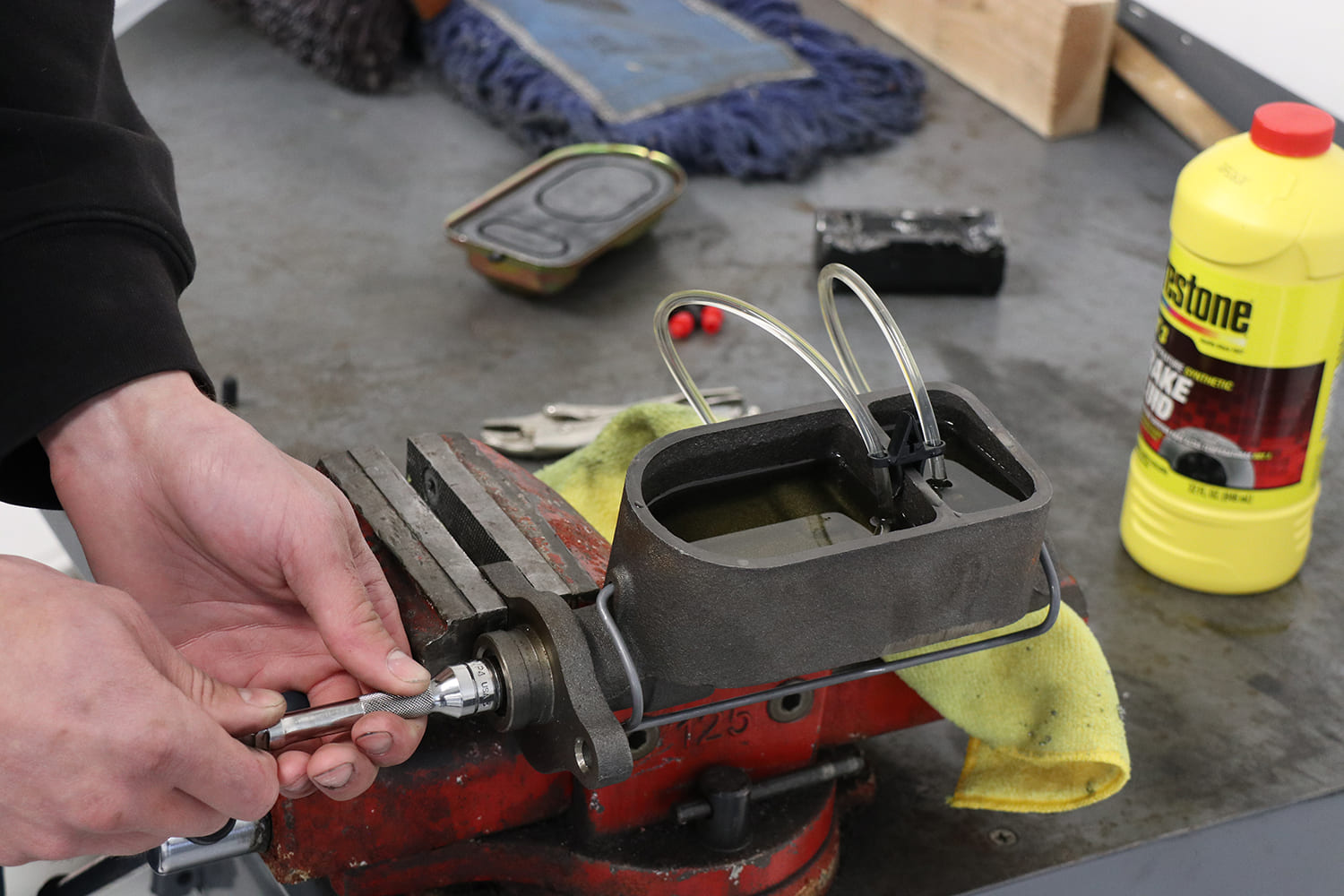
The last step of any brake installation is bleeding the air out of the system, as air will cause a soft, spongy pedal. Before installation it is recommended to bench the master cylinder as shown in the following photos. Then with the master cylinder bled and installed, the rest of the system is bled by starting with the brake furthest away from the master cylinder then working in order to the brake closest to the master cylinder.There are a number of methods to bleed brakes—pressure bleeders that force fluid from the master cylinder through the system, vacuum bleeders that draw fluid through the calipers with a pump, or the tried-and-true method of pumping the brake pedal with a hose connected to the bleeder screw on the caliper and the other end in a bottle. However it’s done, the goal is to get all the air out of the system.
With a new dual master cylinder the Mustang’s brake system is arguably safer in the unlikely event of a hydraulic leak than it was with the original single-circuit master cylinder. But the difference in stopping power between the factory drum brakes and vacuum-boosted four-wheel discs is where the real difference in performance will be noticeable, and better performance is the name of the game hot rodders play.
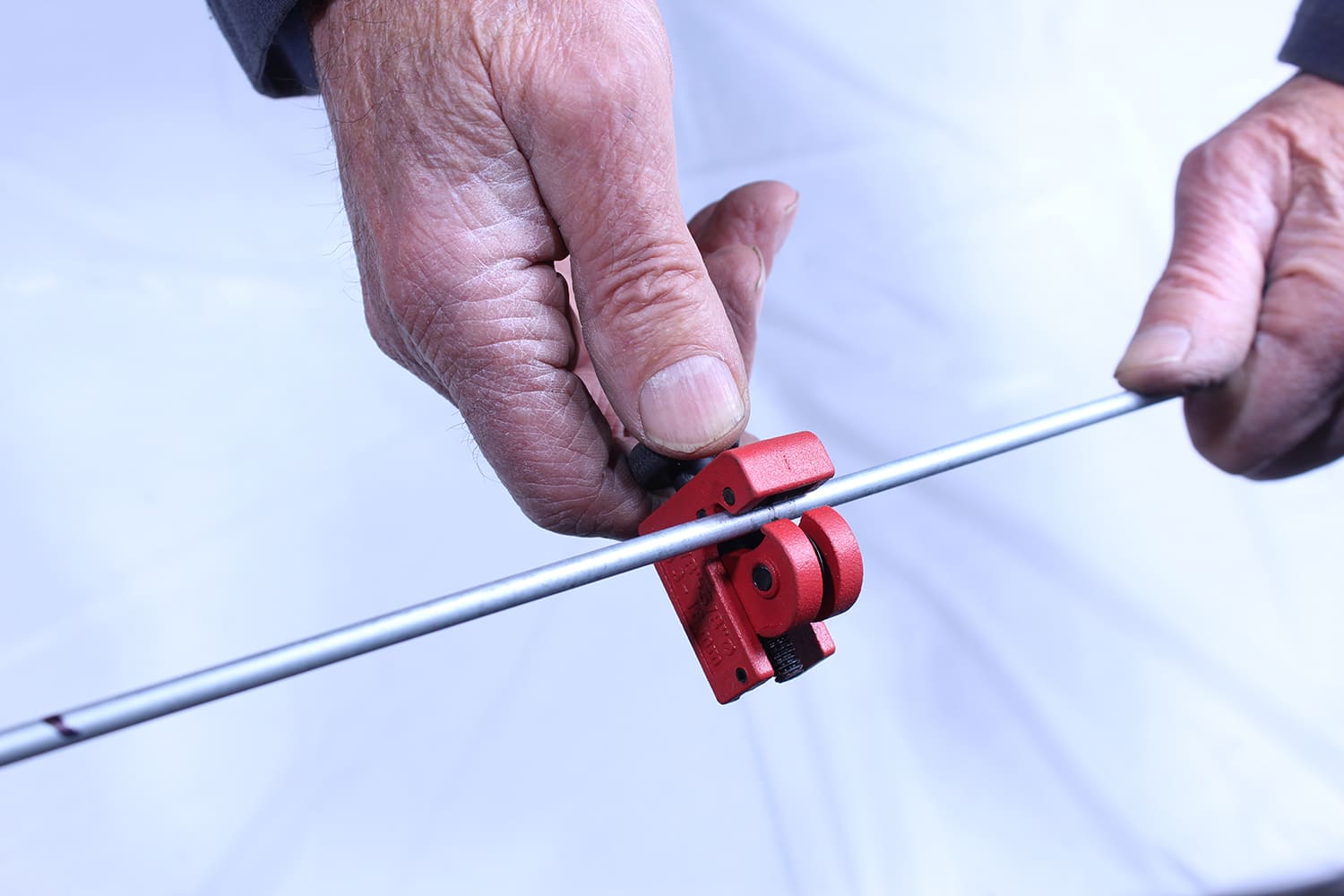
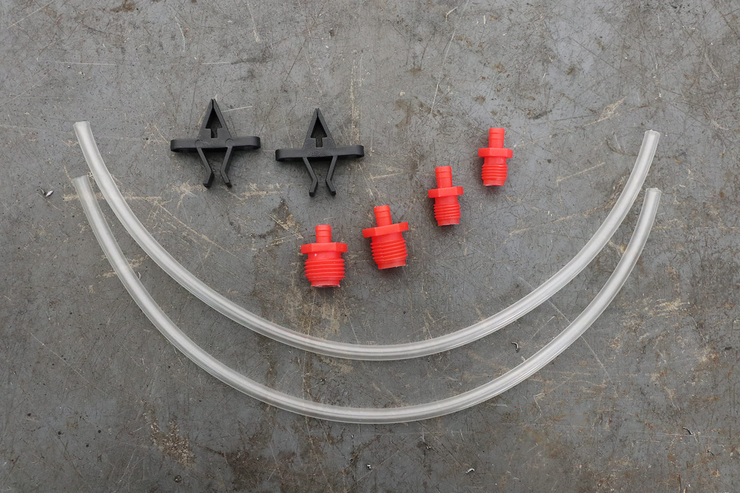
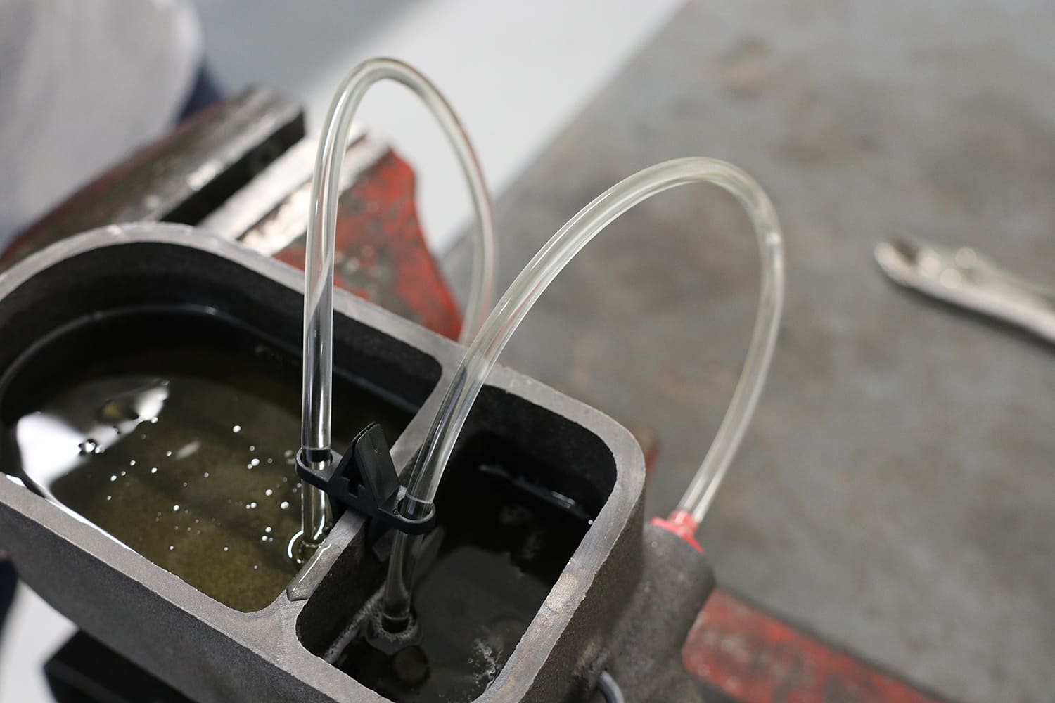
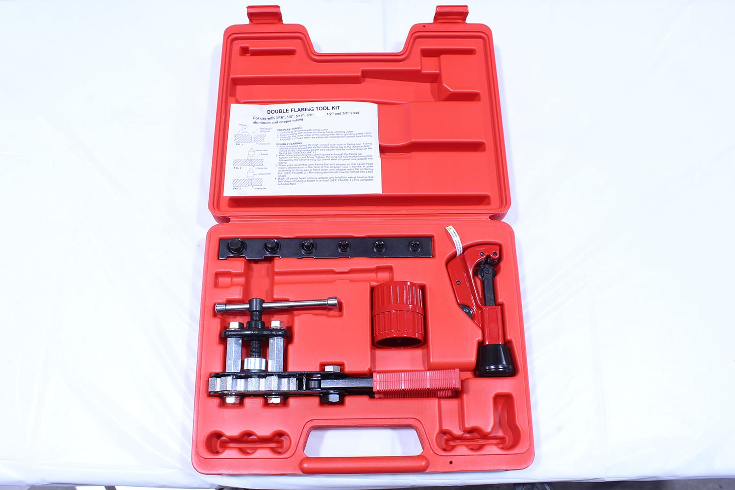
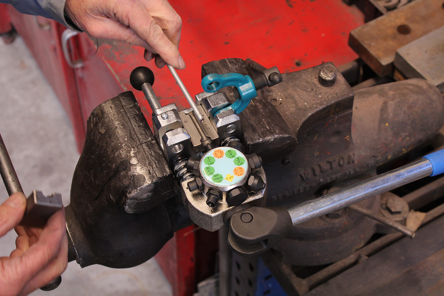
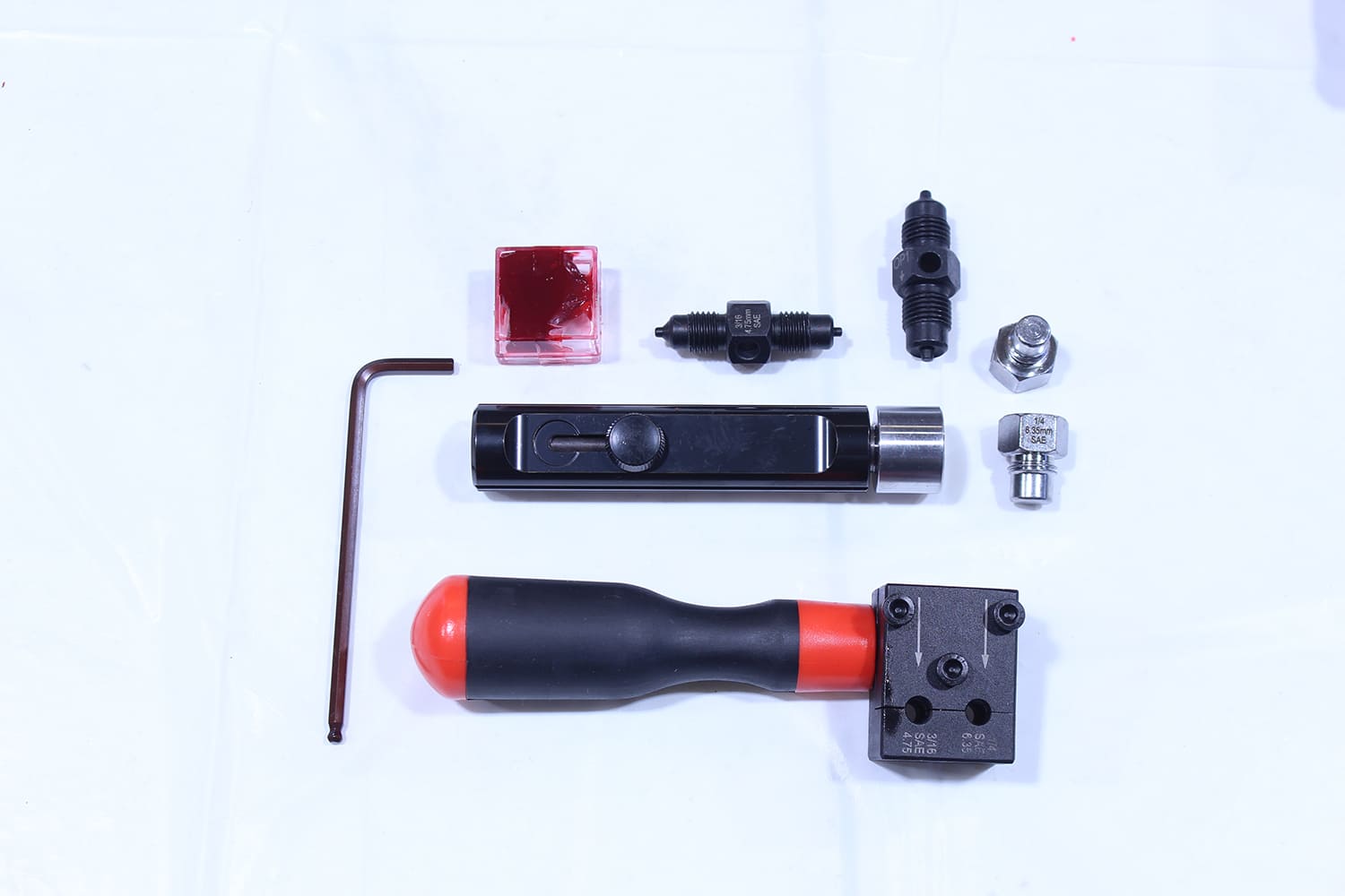
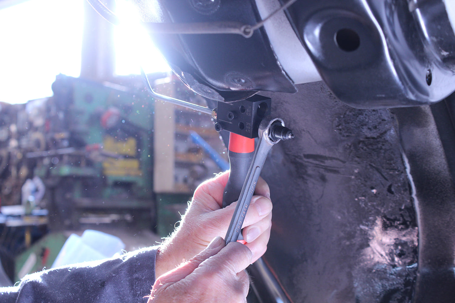
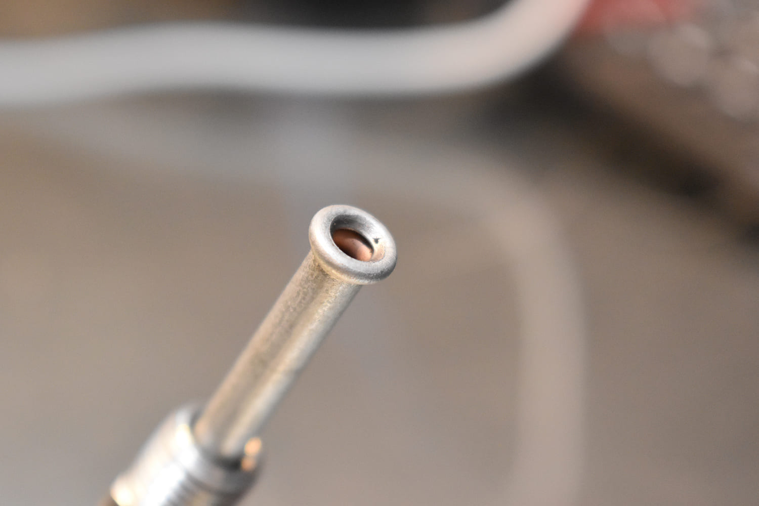
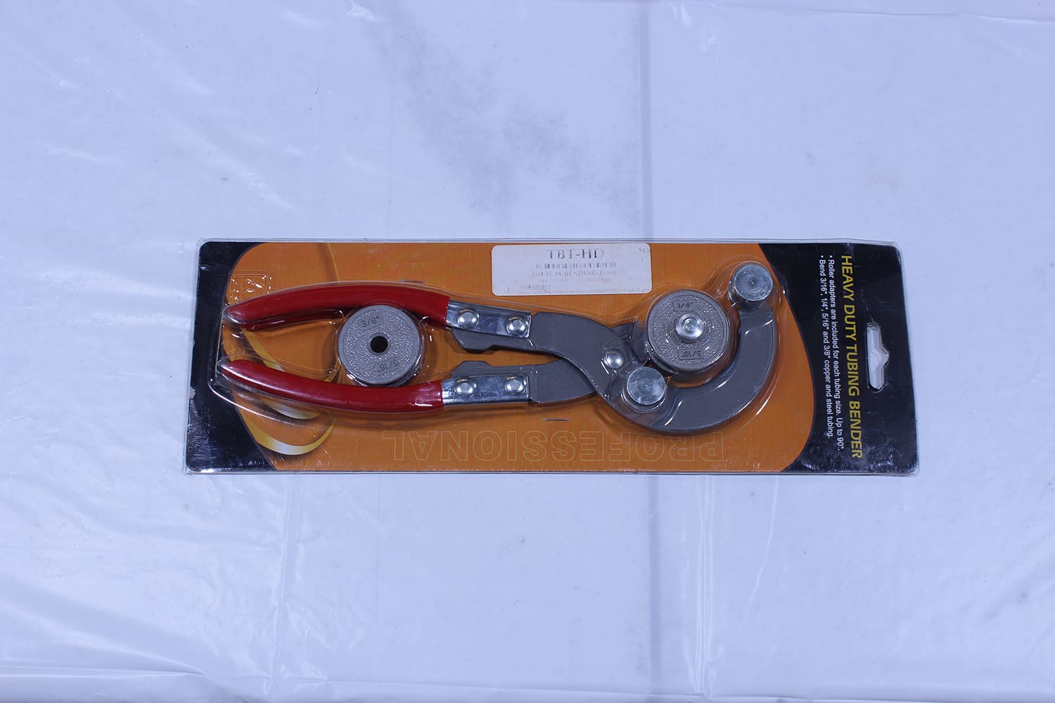
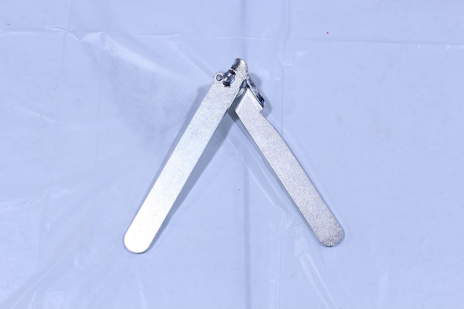
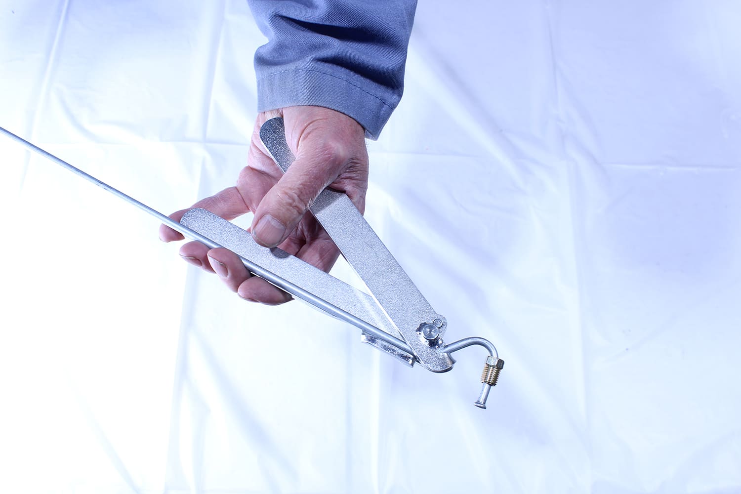
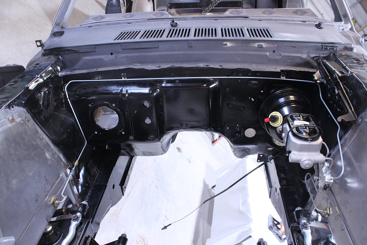
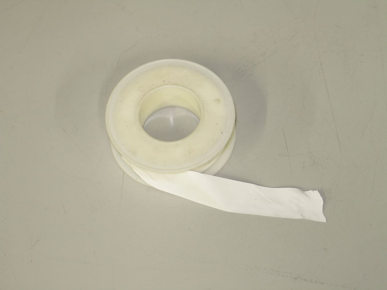
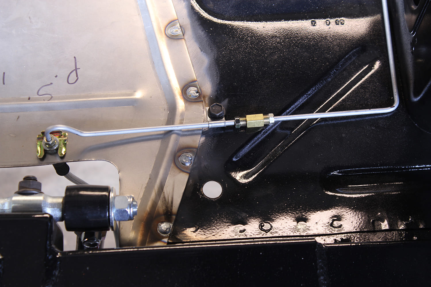
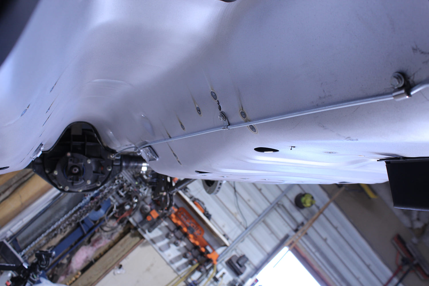
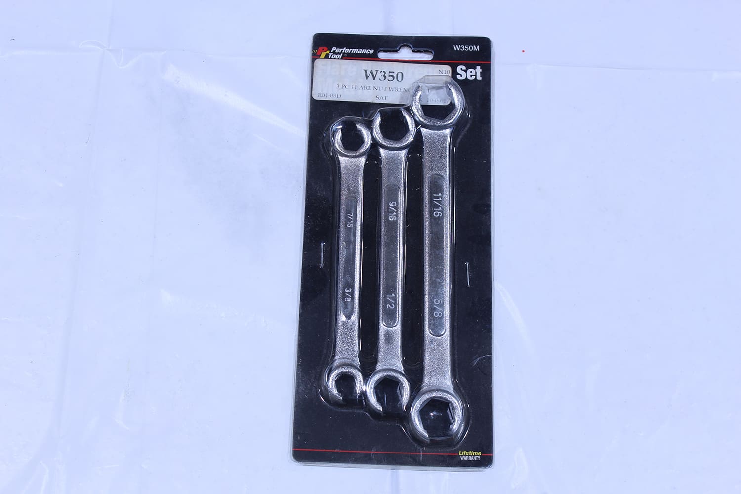
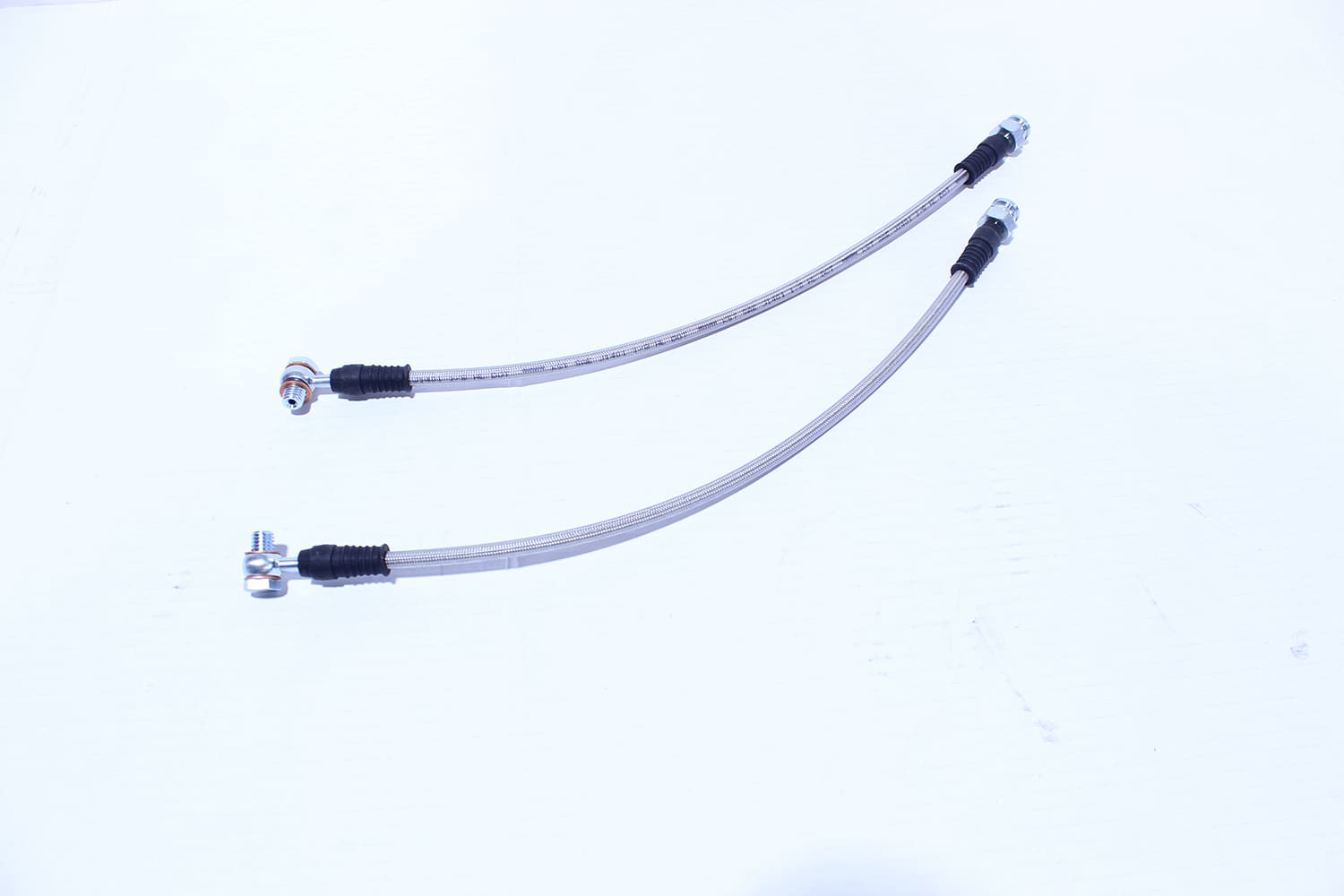
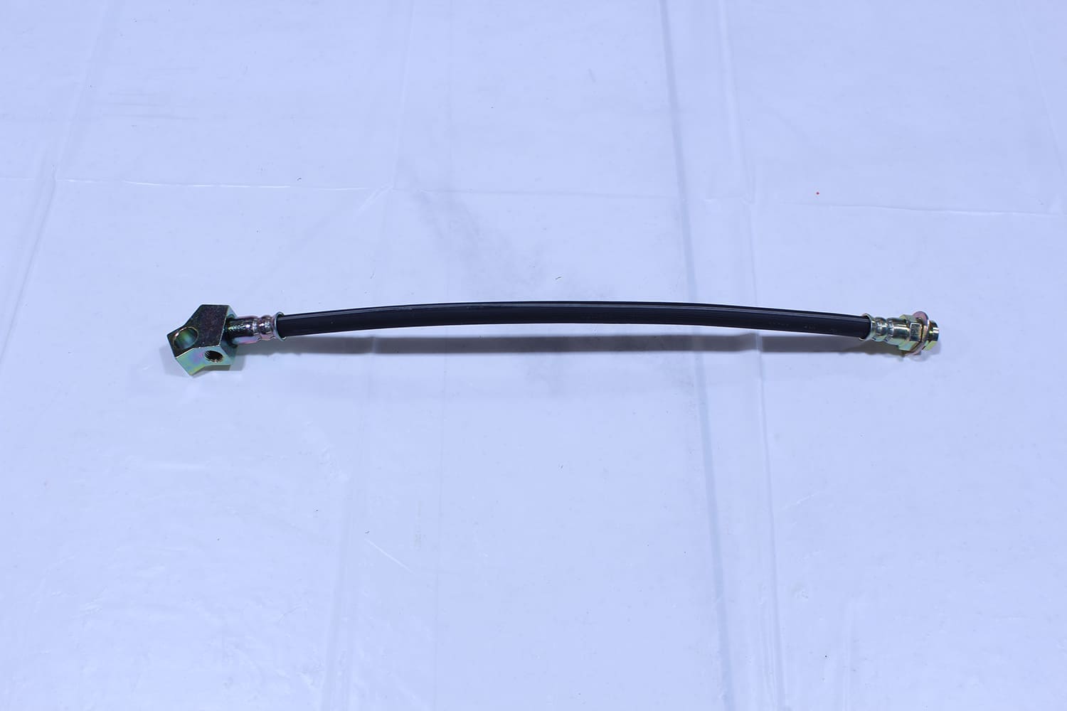
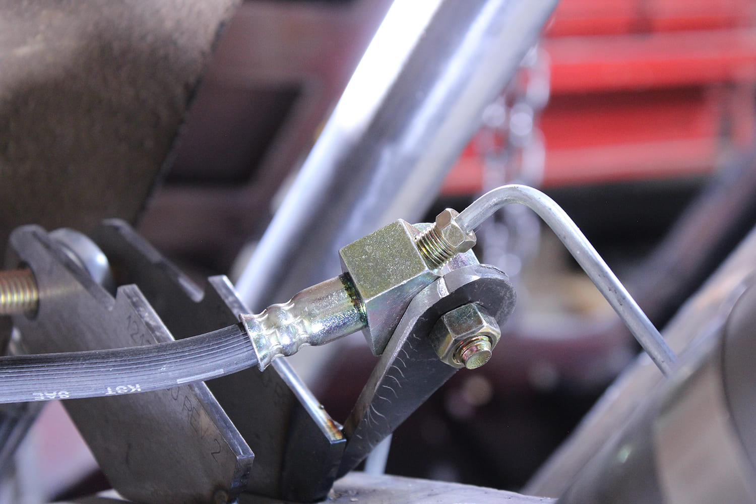
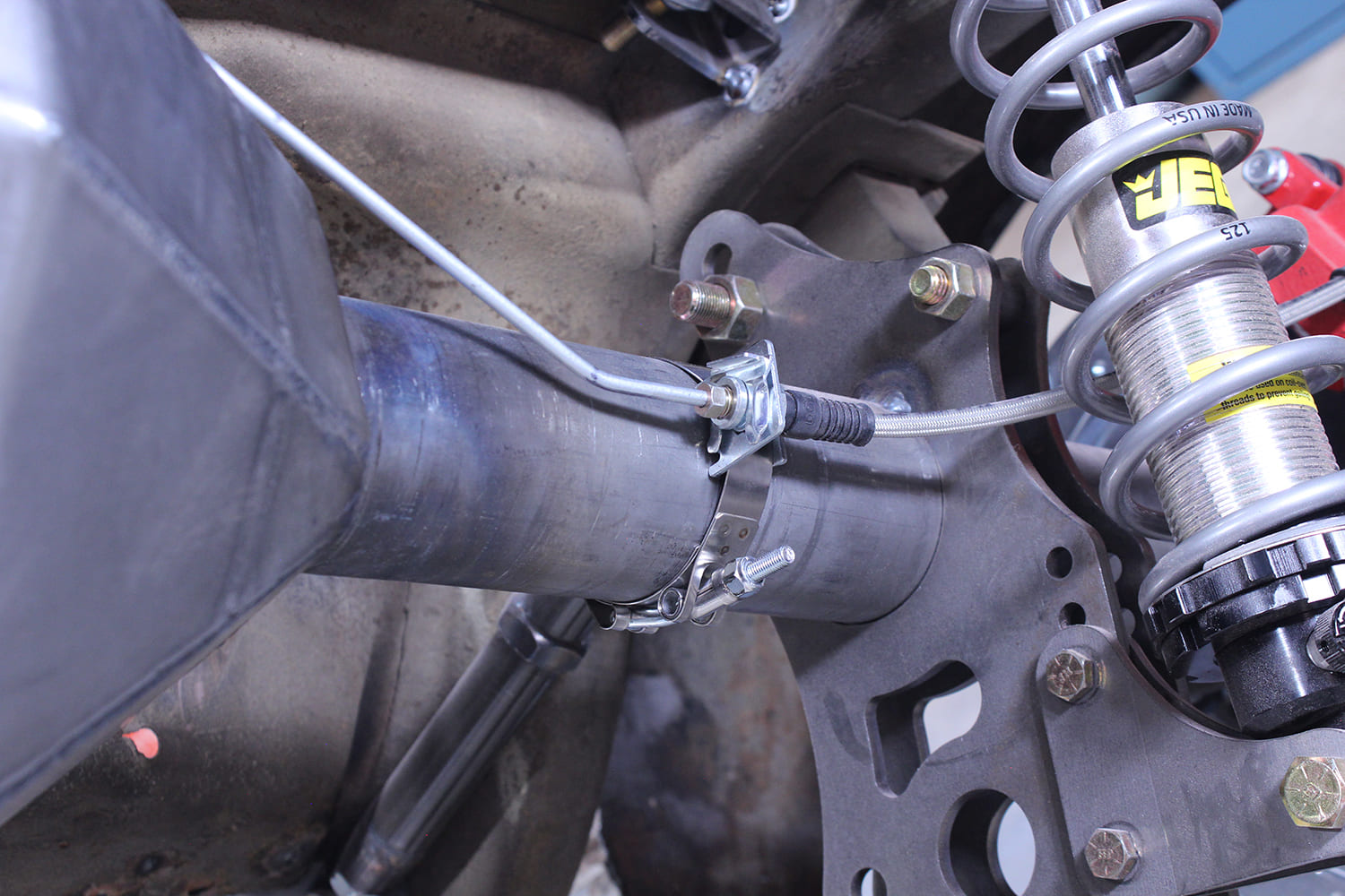
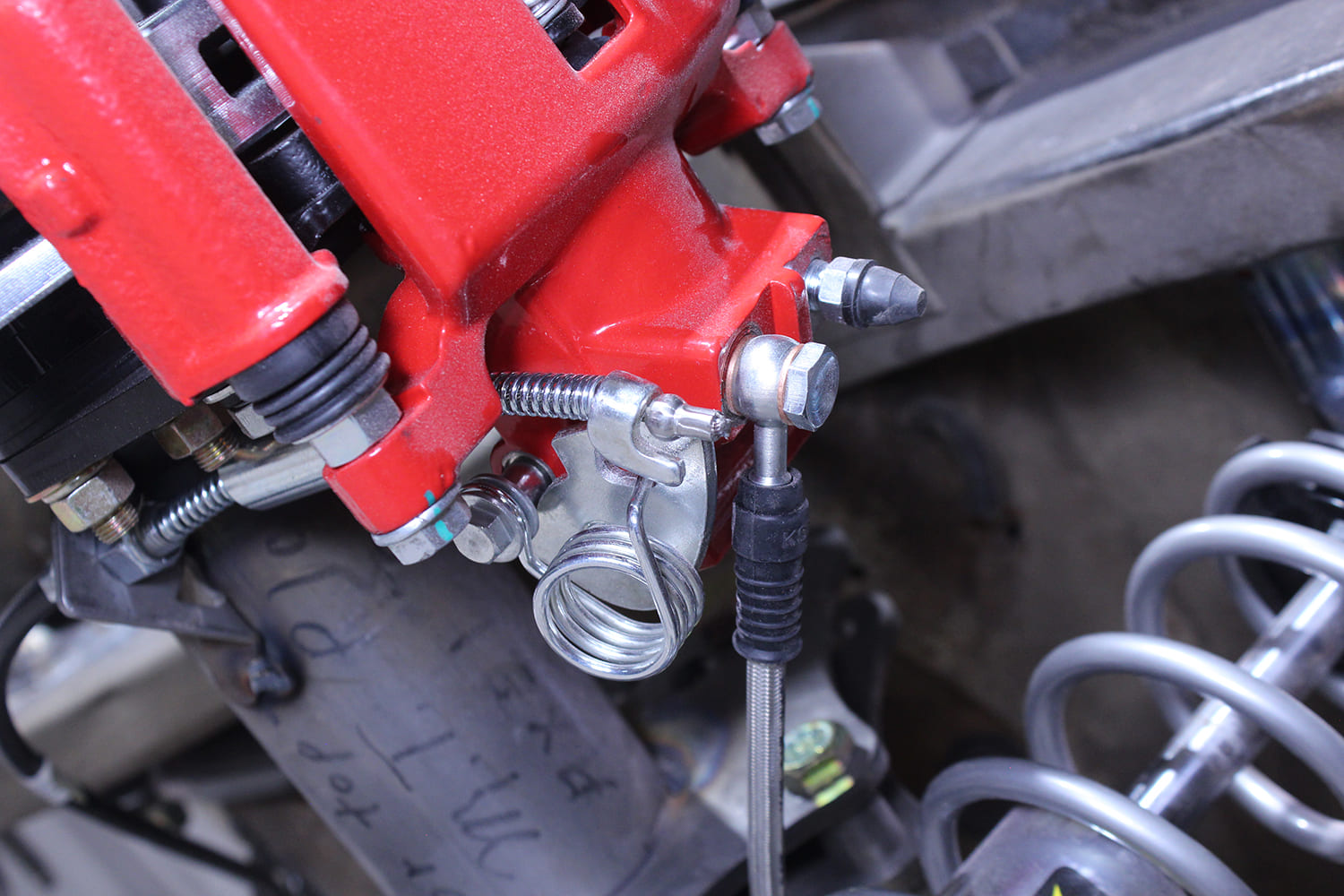
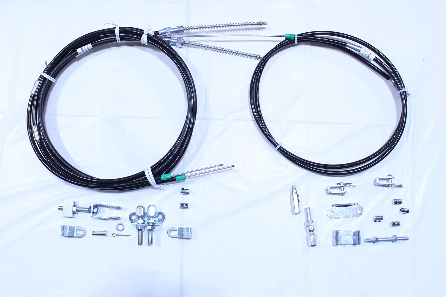
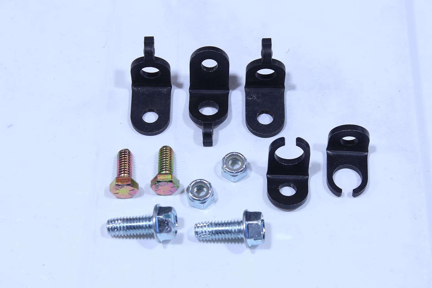
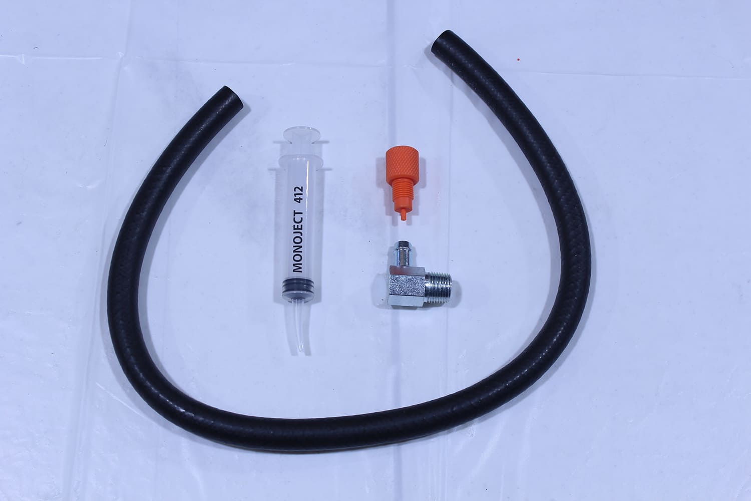
CPP’s handy little master cylinder bench bleeding kit is PN CPP-BK. It simplifies the process of bench bleeding by not squirting fluid everywhere. The included adapters fit the common outlet sizes.With the plastic lines connected to the master cylinder’s outlets and submerged in the reservoirs, a screwdriver or socket extension is used to pump the pistons.Stroking the pistons will push any trapped air into the reservoirs as evidenced by the bubbles. Note the clip that holds the hoses in place.Radford elected to plumb his Mustang steel brake lines. He used a CPP universal brake line kit (PN SLS-04). It came with 60 feet of 3/16-inch line, a variety of adapters, tube nuts, and unions.CPP offers a variety of double flaring tools, this example is their Deluxe Dual Flare Tool Kit (PN CPDFT-D). It includes a tube cutter and flares for 3/16-, 1/4-, 5/16-, 3/8-, 7/16-, and 1/2-inch lines.This tool simplifies the process of creating precise 45-degree double flares in brake lines. This tool is mounted on a bench vise and makes double flares in two easy operations. Found under PN CPBFT, it works on 3/16-, 1/4-, and 5/16-inch tubing.Another double-flaring tool from CPP is this simple, easy-to-use handheld version (PN CPDFTK-PDT). The kit handles for 3/16- and 1/4-inch tubing.The advantage of the handheld flaring tool is that it can be used in cramped spaces on a line that is in place on the car.This is what a 45-degree, double flare looks like. The tubing is flared then folded back onto itself to create a double-thick sealing surface.Shaping brake lines by hand is seldom successful; to make smooth, consistent bends CPP offers this tool (PN TBT-HD).Simple solutions are often the best, and CPP’s brake line tool (PN CPBLB) is certainly that.We were pleasantly surprised at the quality bends the CPP tool made, some as tight as 1/2-inch inside radius with bends up to 270 degrees.Clean, tightly formed, and properly secured with clamps, the new brake lines follow the original factory routing.Steel brake lines with 45-degree flares require inverted seat fittings. The seat in the fitting and the flare on the tubing and the shape of the tubing nut all combine to make a leak-free seal.Something that should never be used on inverted flare fittings is thread sealing tape. It’s intended to seal pipe threads, which may be found on the fitting in some disc brake calipers.This is the steel brake line leading to the right front caliper. The line is secured to the inner fender panel with the proper clip that holds the caliper’s flex hose; the steel line is secured with a clamp and the proper inverted flare coupler is used to connect two sections of brake line.Just as Ford had it at the factory, the brake line to the rear of the car runs along the driveshaft tunnel. It’s secured to the sheetmetal with factory-style clamps.If you’ve ever rounded brake fitting with an open-end wrench you’ll appreciate these brake line fitting wrenches. The three-piece set (PN W350) fits SAE 3/8, 1/2, and 5/8 tubing nuts.To connect the front calipers Radford used braided stainless steel lines from CPP. Available in various lengths they have inverted flare fitting at the chassis end and connect to the calipers with “banjo” fittings and bolts. Note the copper sealing washers on both sides of the caliper connection.At the rear the steel brake lines connect to the rear axle housing with an original-style 1965-66 flex hose, CPP PN RFH67. The big hole is for the factory axle vent that also secures the hose end to the housing.Radford attached a fabricated bracket to the rearend housing and secured the hose to it with a bolt through the factory mounting hole.Steel lines run from the flex hose to each side of the axle housing. On each side the steel lines connect to stainless steel flex hoses with inverted flare fittings. The flex lines are held in place with CPP’s Rear Brake Hose Tab Kit (PN RBHTK).Like the front brake hoses, the rear hoses connect to the calipers with banjo fittings and bolts.Radford used CPP’s universal brake cable kits to connect the original parking brake handle to the rear disc brake calipers. On the left is the rear cable kit that works with both disc and drum brakes (PN CP-UBCK). On the right is the front cable kit (PN 90352).To secure the parking brake cables to the body CPP offers their Universal Parking Brake Cable Mount Kit (PN UBCM).This is CPP’s vacuum hose kit to connect the brake booster to the intake manifold. It includes 25 inches of vacuum hose, a fitting for the intake manifold, and a master cylinder bleeding syringe (PN PDBI-K25).
We use cookies to ensure that we give you the best experience on our website. If you continue to use this site we will assume that you are happy with it.