When the Part You Need is Virtually Impossible to Find in a Wrecking Yard
By Ron Covell – Photography by Adam Cecil
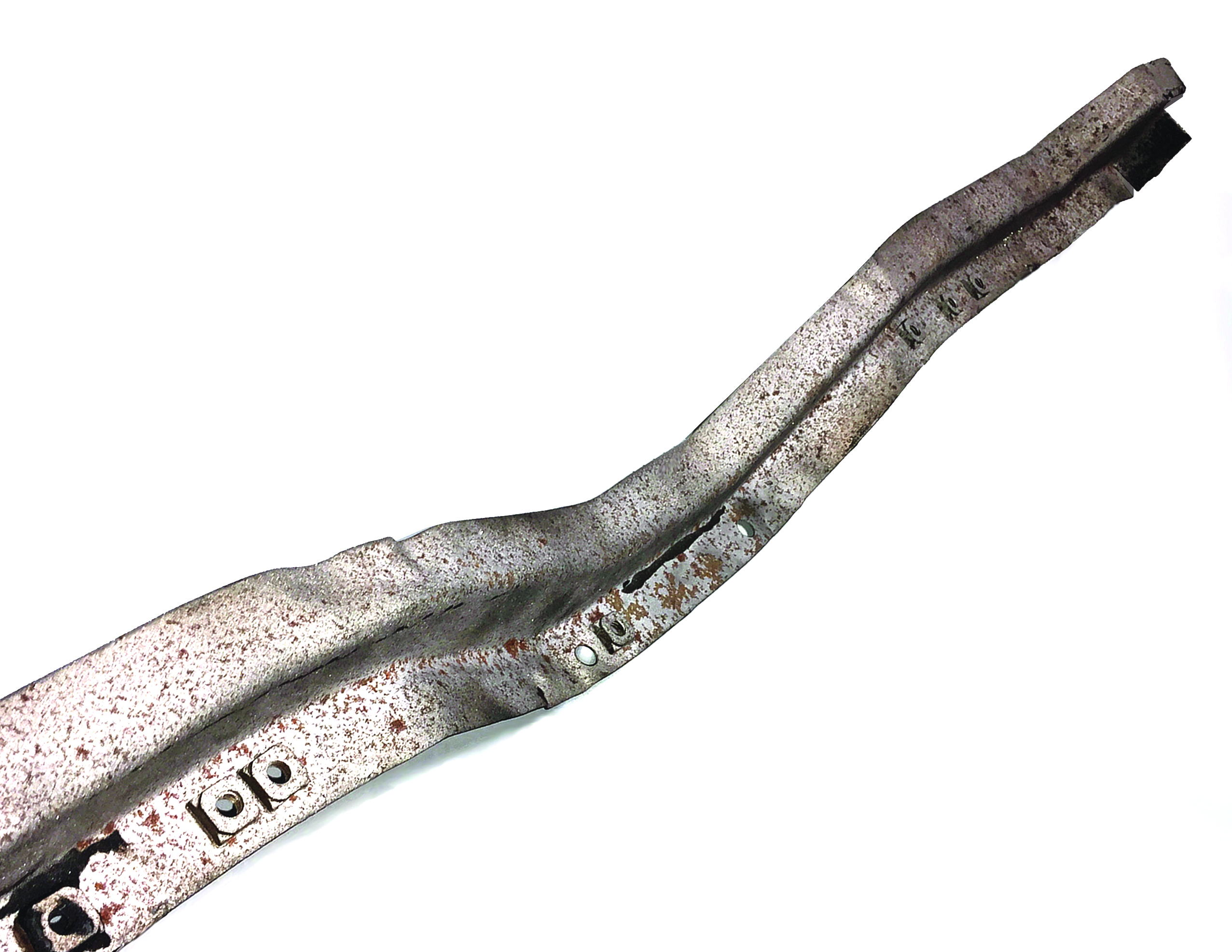
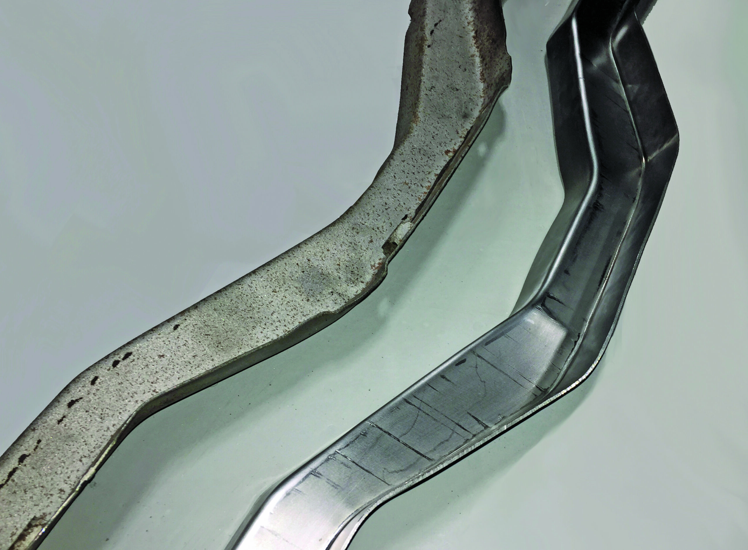
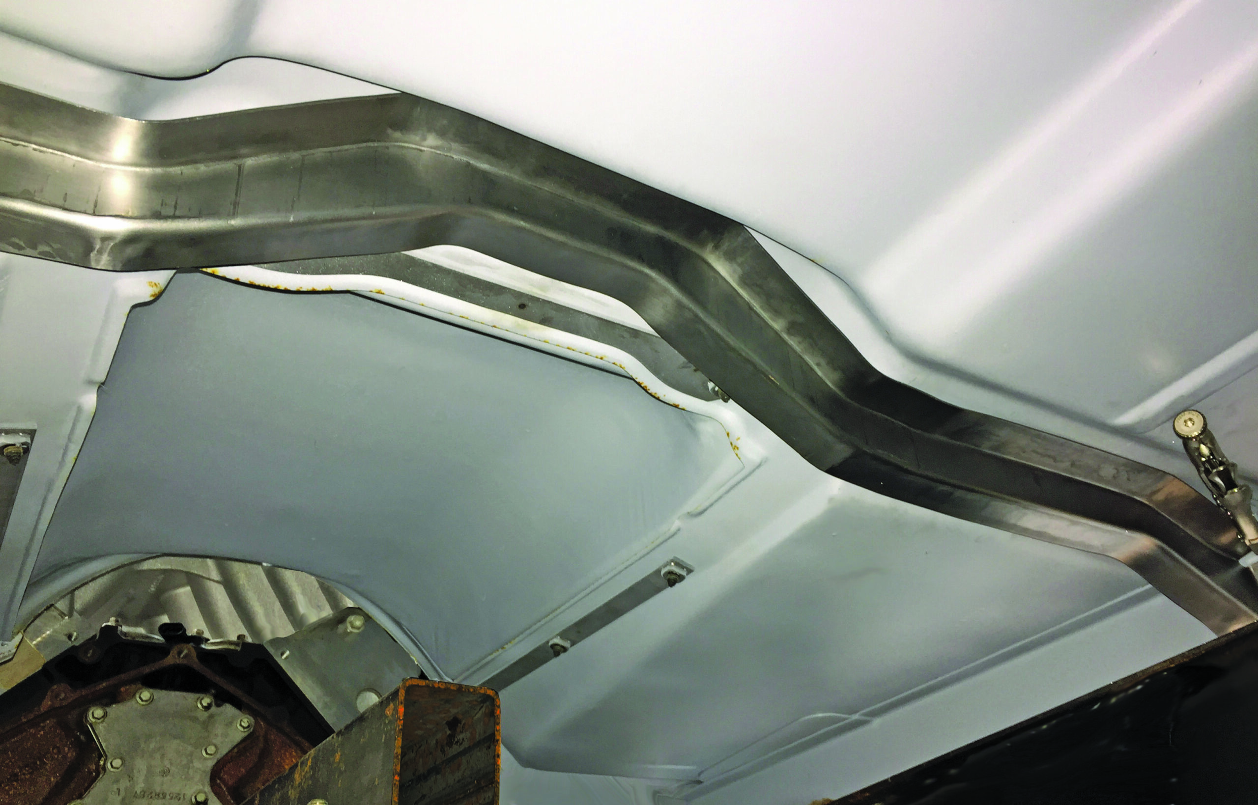
The aftermarket provides an abundance of reproduction parts for classic trucks, but there are some parts that are not available. One of these is a bucket seat cab brace for a 1969-1972 Chevrolet C10—and they are virtually impossible to find in wrecking yards.
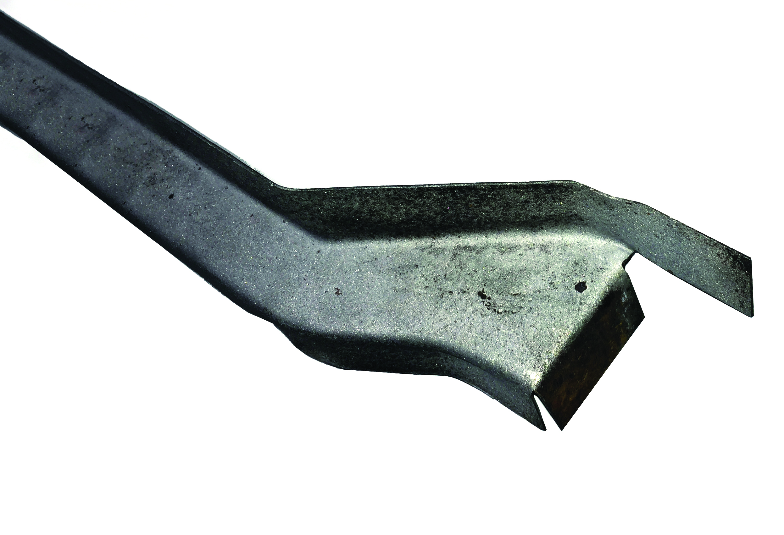
Adam Cecil is building a C10. Being a person who likes challenges, he hatched the idea of making his own seat brace by utilizing the hammerforming process. A lot of people think that anything shaped with a hammer could be called “hammerformed,” but the specific process we are describing involves making a form of some durable material, holding a piece of metal tightly against it, and then hammering the metal until it takes the shape of the form beneath it. This is distinctly different from the freehand way metal is sometimes shaped with a mallet and sandbag, or with a hammer and handheld dolly.
The hammerforming process is ideal for many types of parts, and it’s most beneficial when a number of identical parts are needed. For thin or soft metals the forms can often be made from wood or plastic, but this particular brace is made of 16-gauge steel, so an extremely robust form is required. Also, Cecil presumed that he was not the only person who would need a seat brace, so he made his form durable enough to make dozens of parts, if necessary. That’s why he made this hammerform from solid steel.
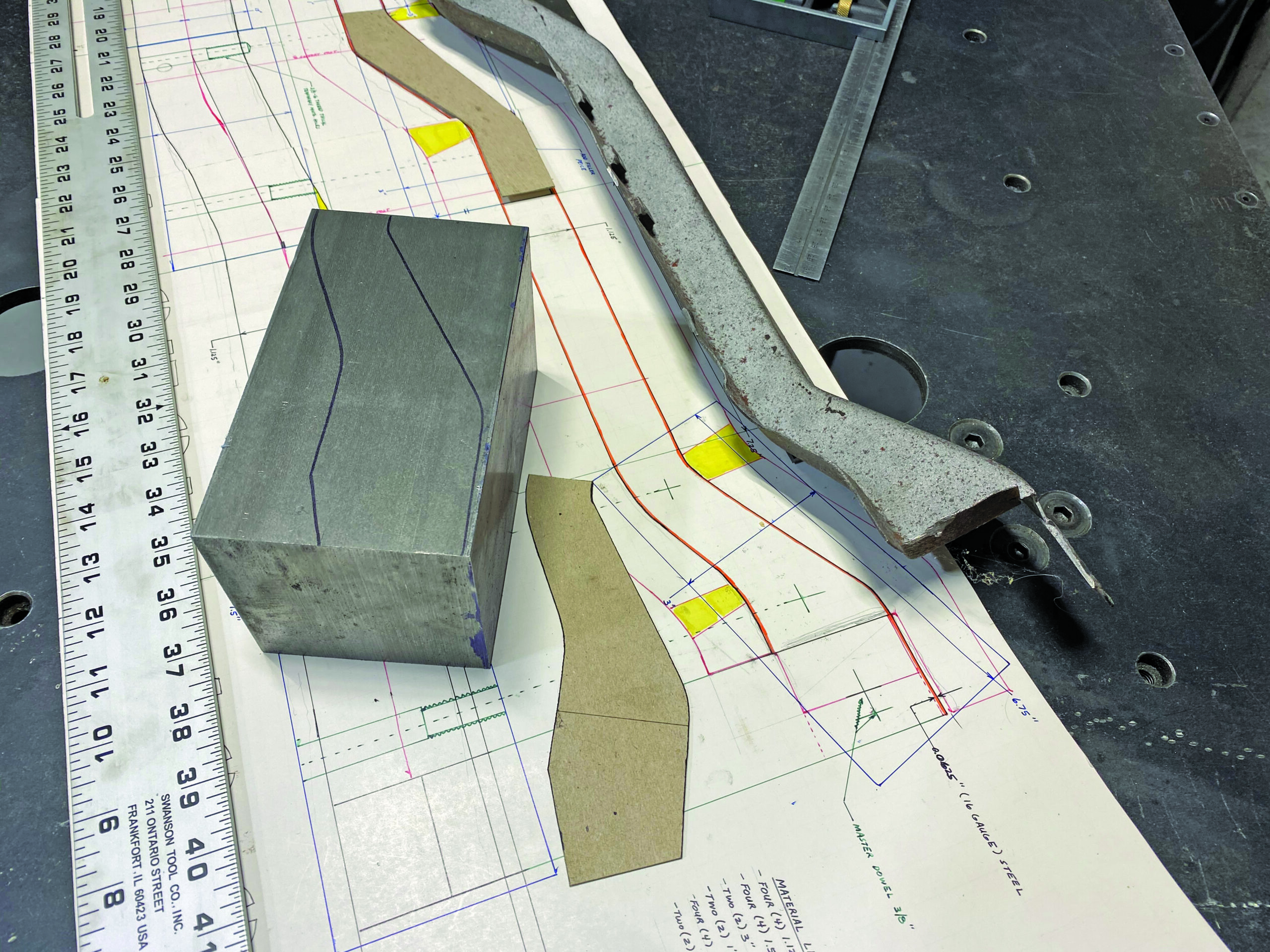
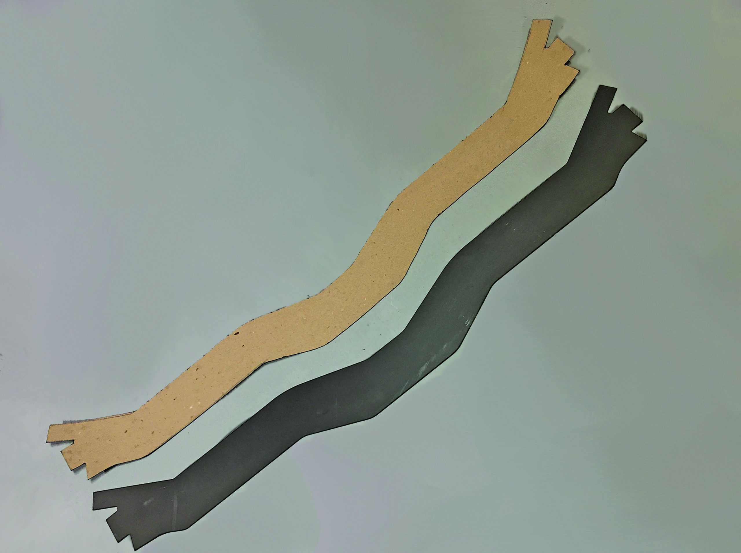
The first step is making an accurate, fullsized drawing of the part. This drawing is essential for determining the size and shape for each element of the hammerform, and to develop the pattern for the metal blank to be shaped over the form.
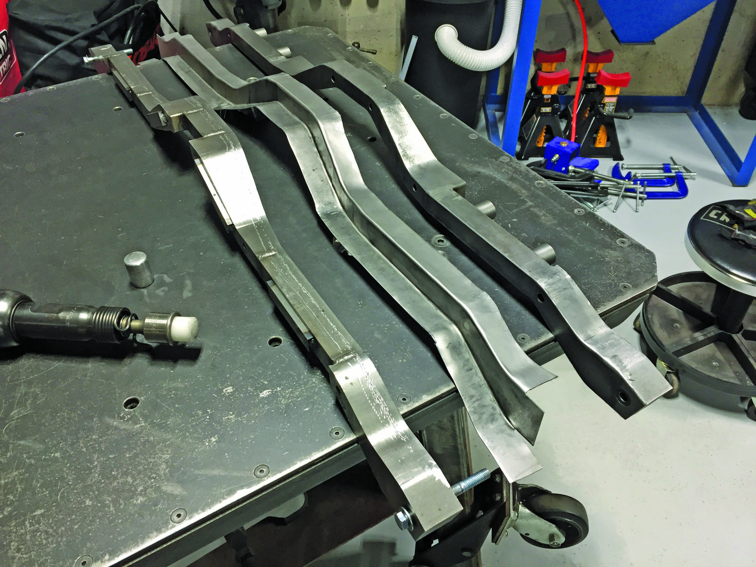
Armed with all the necessary contours and dimensions, Cecil used a small bandsaw to cut the stock and the largest pieces were profile cut from sections of 3-inch square cold-rolled steel bar. That required a LOT of cutting, but he reports the small saw (equipped with an aftermarket base that holds it vertical) did an admirable job—although it did require focus and patience.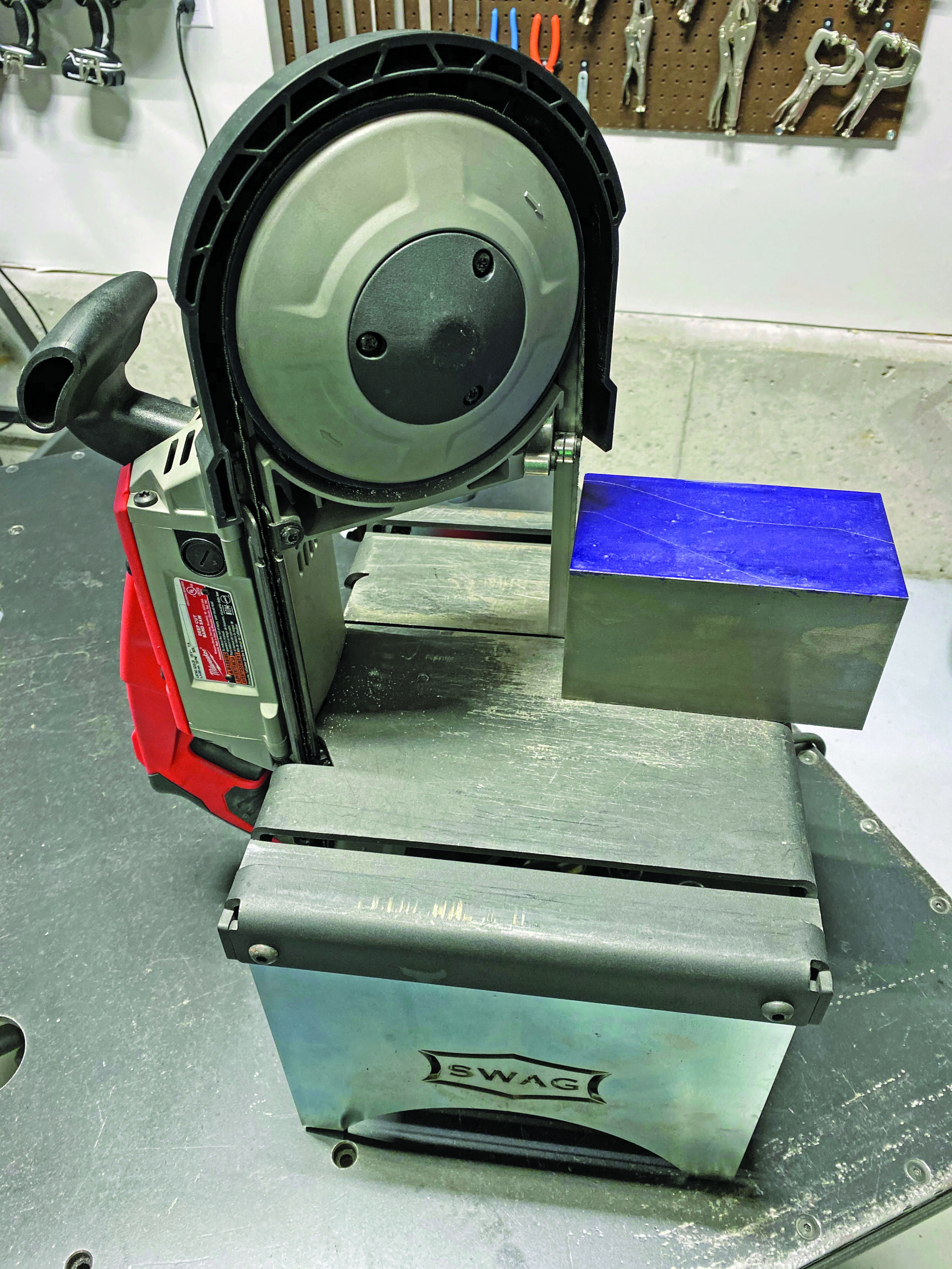
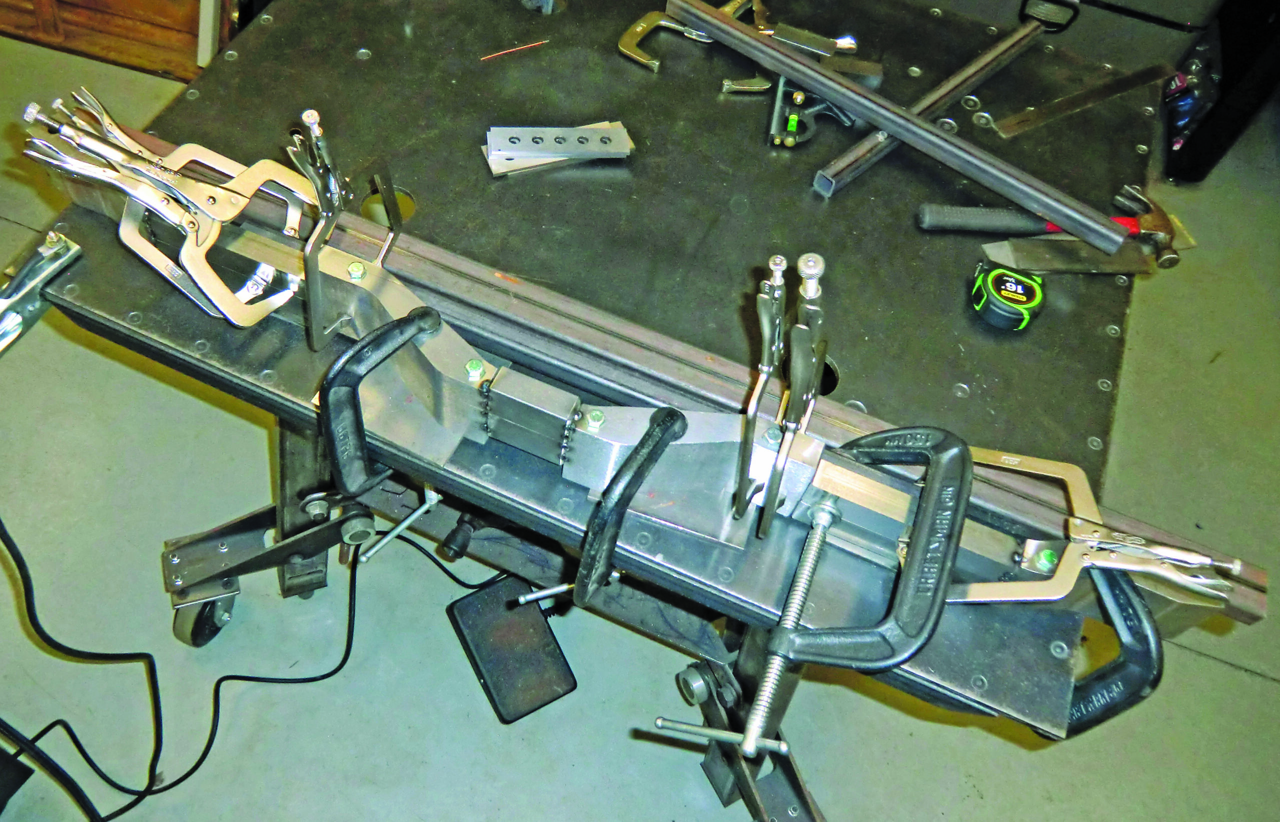
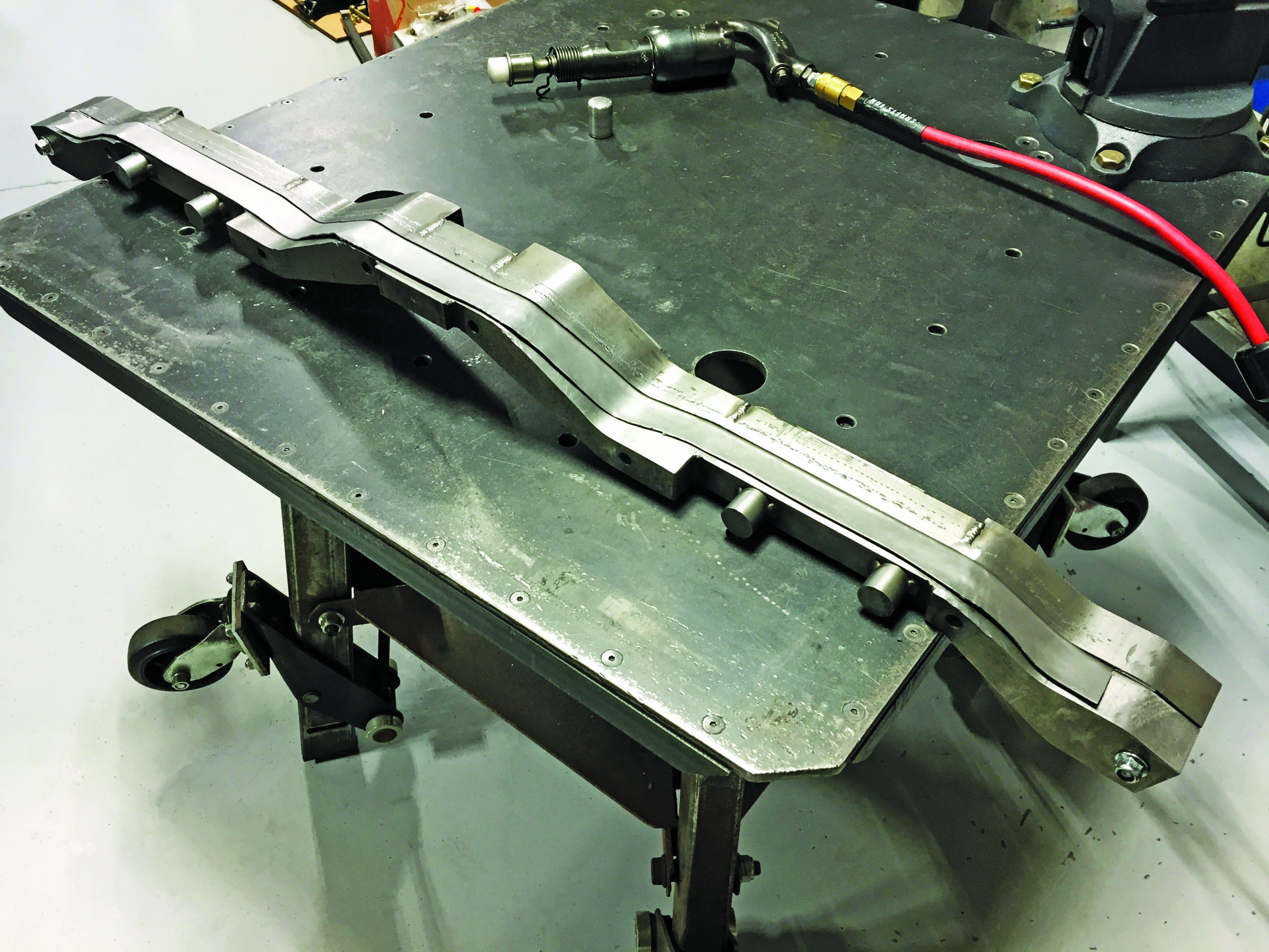
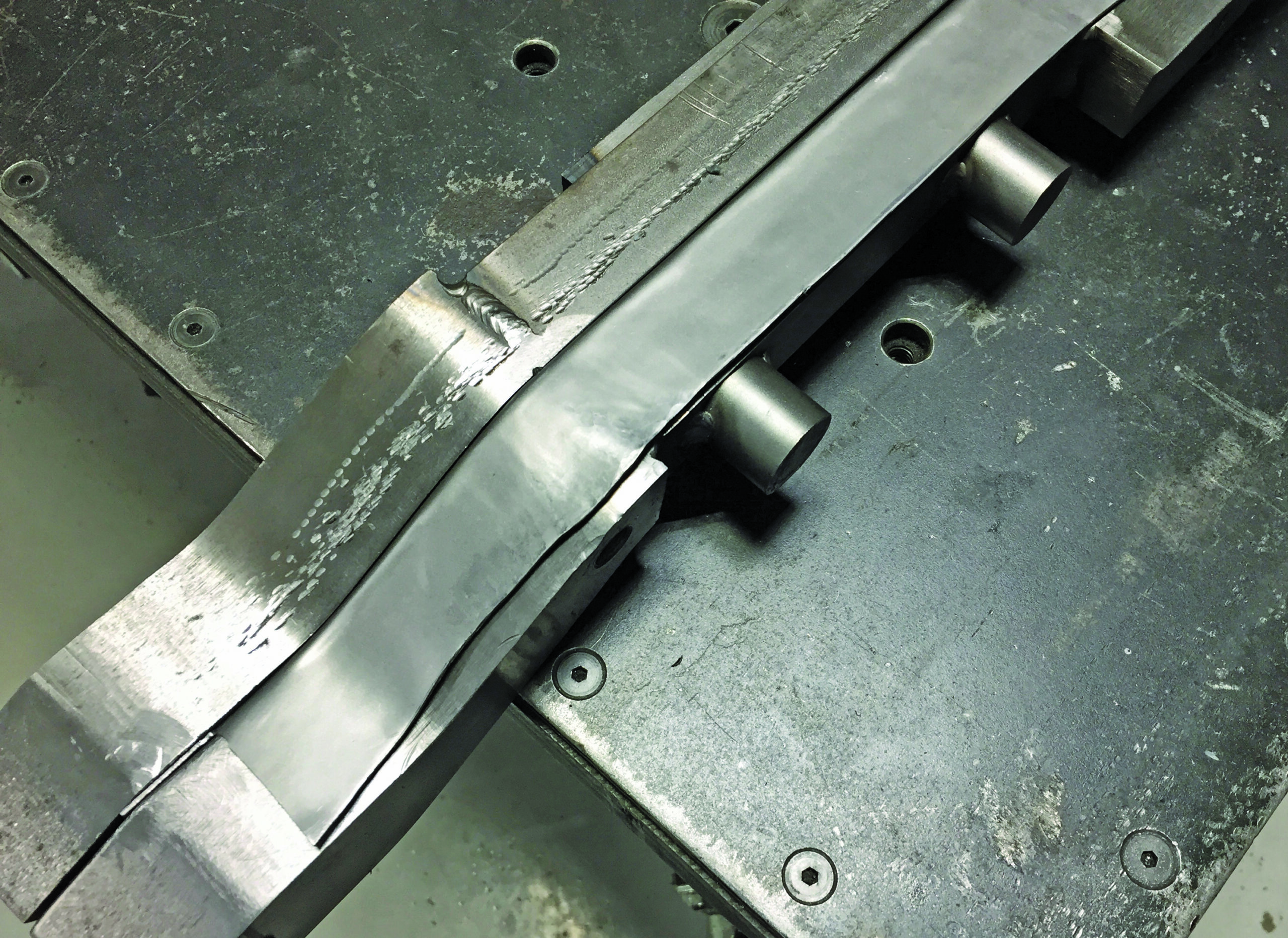
After all the parts were cut to size, they were carefully aligned on a flat steel bench, then clamped securely in preparation for tack-welding. After tacking and a final check of all dimensions, the welds were finished and any bumps in the working surfaces were ground smooth.
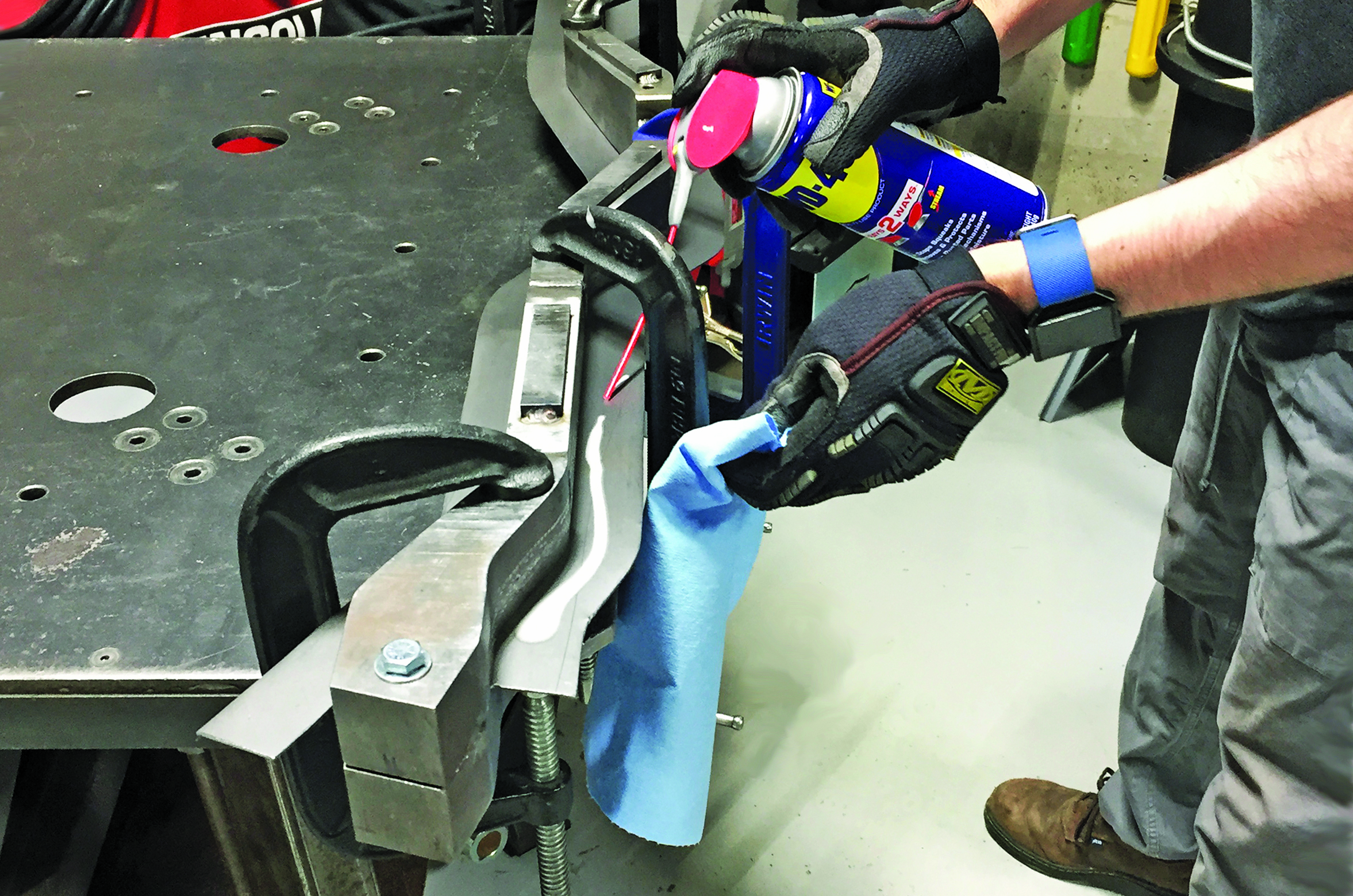
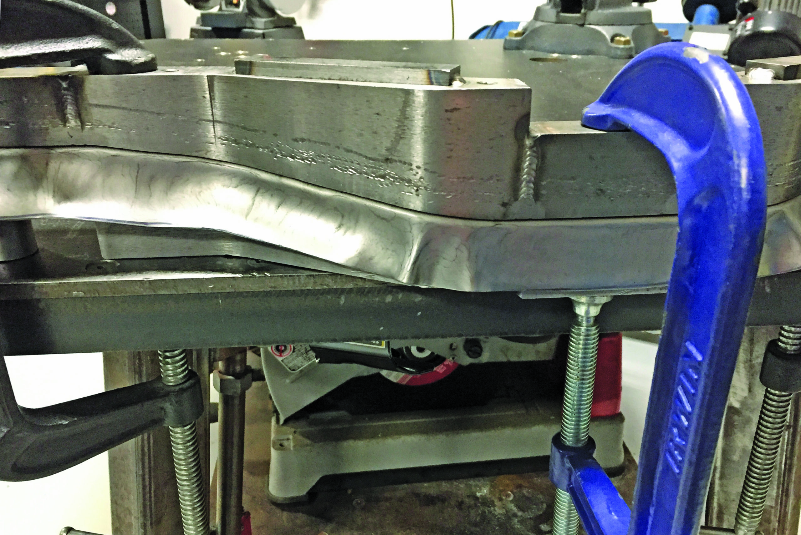
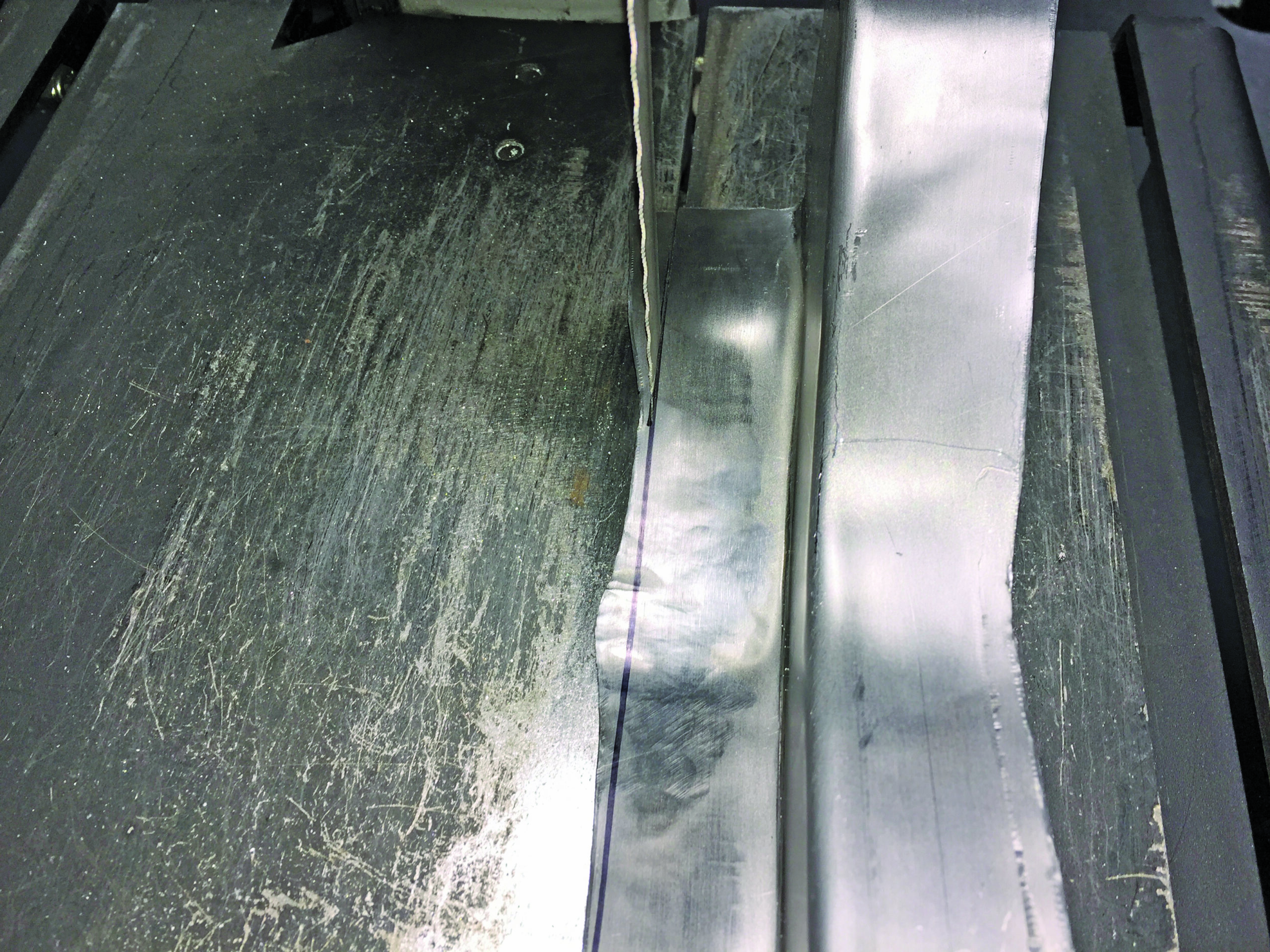
The next step was cutting a metal blank, then placing it between the halves of the hammerform, and drawing them together by using C clamps (plus a couple of bolts at the end, which also provided alignment). This formed the blank in one plane.

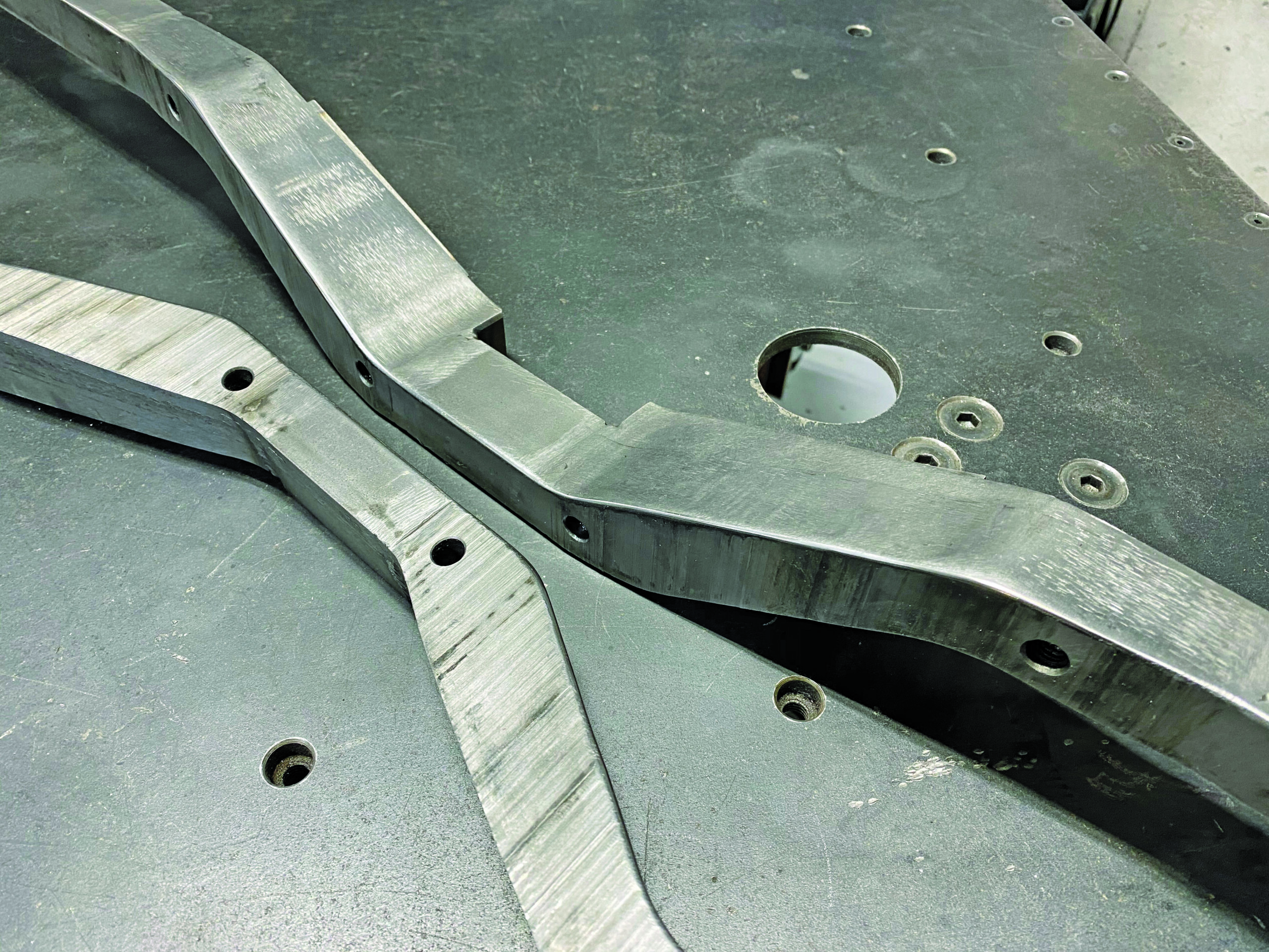
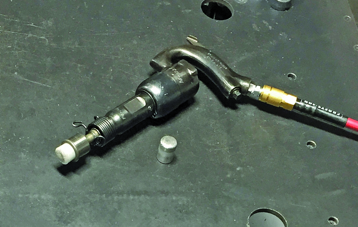
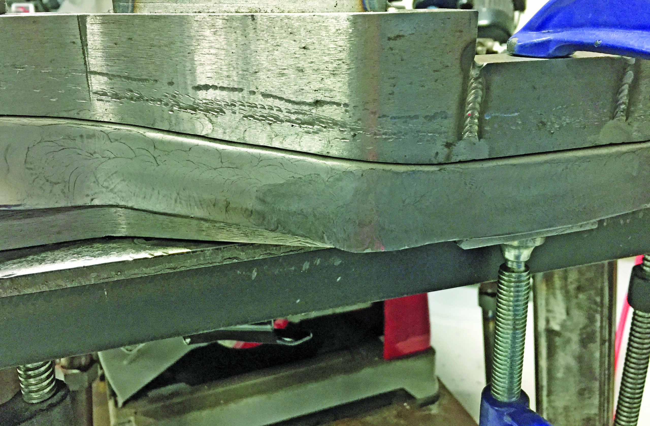
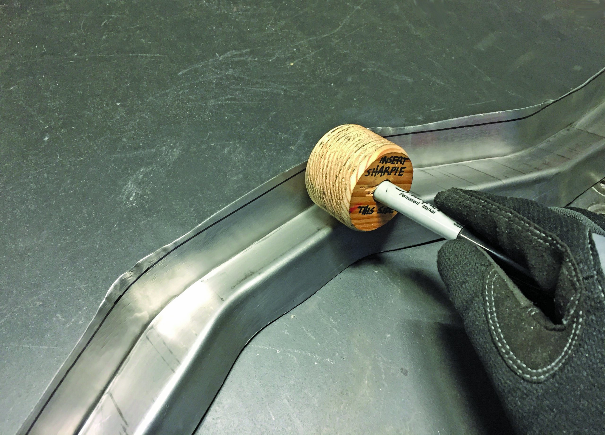
With everything clamped tight, Cecil used a heavy-duty aircraft rivet gun to start moving the first flange down. His rivet gun is equipped with a “flow-forming” nosepiece that uses easily replaceable inserts. The majority of the shaping was done with plastic dies. These don’t mark the metal, but they need to be replaced fairly often since they wear quickly when forcing the 16-gauge steel to move. In the areas where the metal requires shrinking (the outside curves), wrinkles start to form as the flange is pushed down. There is a limit to how large a wrinkle a plastic die can flatten, so the aluminum inserts were used to smooth the metal in the problem areas.
The photos show all the steps in the process, and I think you’ll agree that Cecil did a superb job. The hammerforming process can be used to make any number of parts from sheetmetal, so let your imagination be your guide as you think about ways to utilize hammerforms for your own projects!


Sources:
Adam Cecil
adamcecil02@hotmail.com
Swag Off Road
(541) 915-2775
www.swagoffroad.com

TM Technologies
(530) 292-3506
www.tinmantech.com