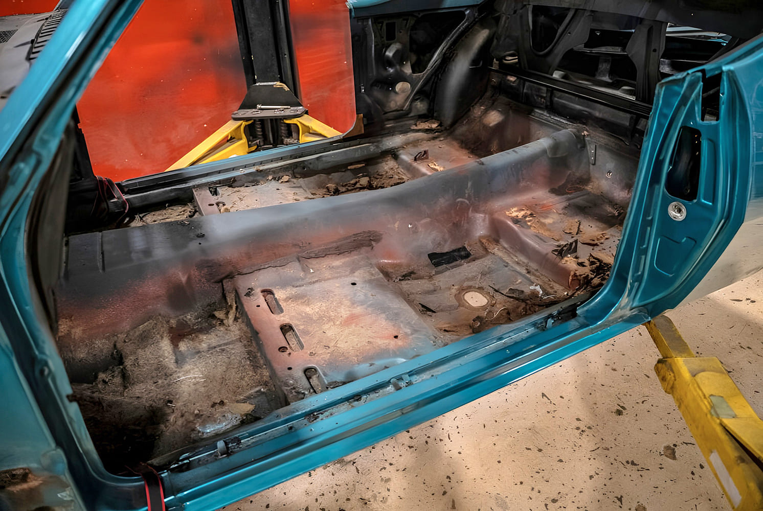
This project was started with the cleanest 1968 Camaro that could be found. It pays to start with a sound car, even knowing from the start that extensive modifications will be made.
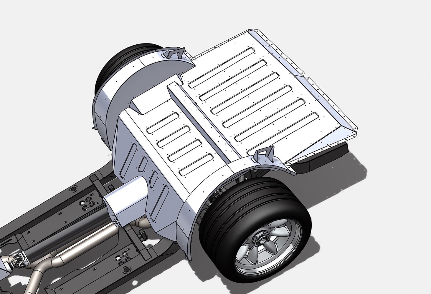
In this article, we’re looking at a 1968 Camaro being built at Roadster Shop. As is typical for a high-end build like this, they started with the best-quality donor vehicle that could be found. After fitting the Camaro body onto one of their Fast Track chassis, they did a complete scan of the body, and Mike O’Brien, the lead engineer at Roadster Shop, carefully designed a new floor to fit over the chassis, which kicks up in the rear to clear the independent rear suspension system.
Typical rust damage was uncovered after stripping the interior of the car, but the majority of the floor will be replaced, so this was not much of a problem.
Doing this work in CAD has many advantages. It was a straightforward process to determine the dimensions and shapes for all the panels, and to pinpoint the location of each reinforcing rib in the floor panels. All Roadster Shop chassis are CAD-designed, so that data was called into play to help design the floor, so it fits neatly to both the body and chassis in every critical area.
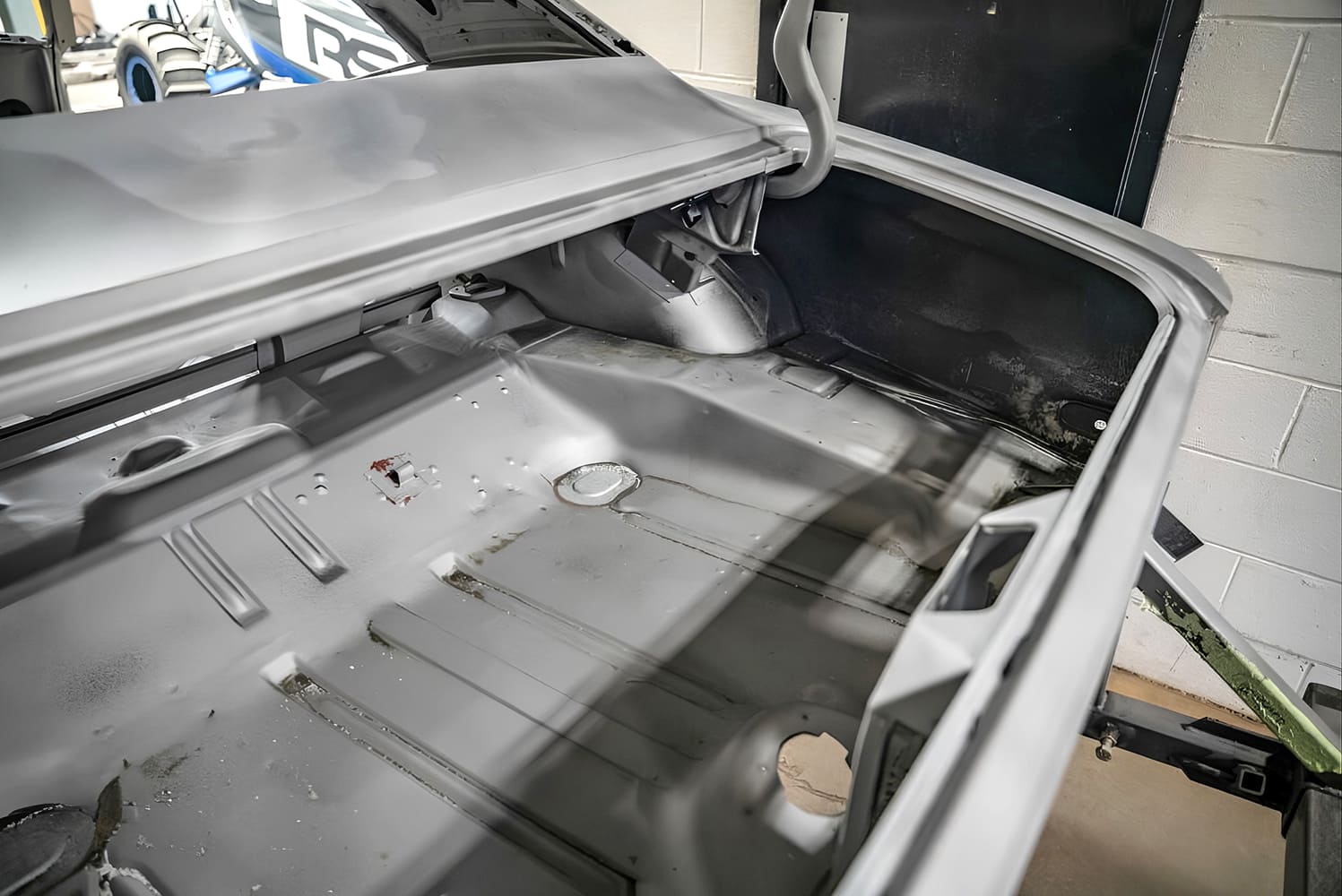
After the body was removed from the frame, it was completely media blasted inside and out.
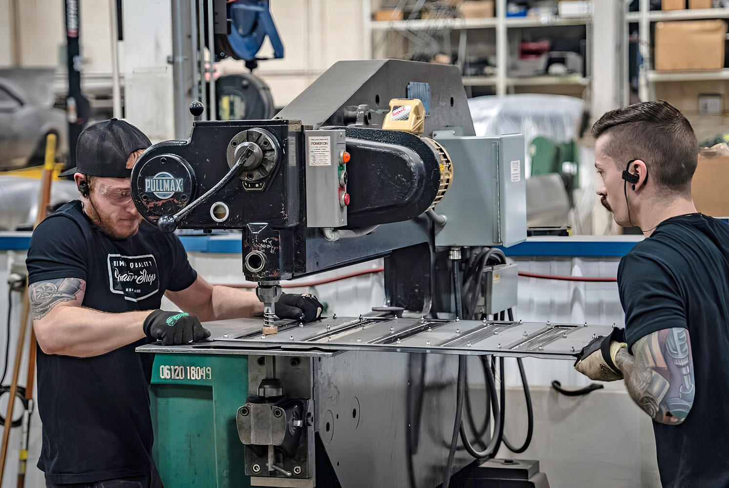
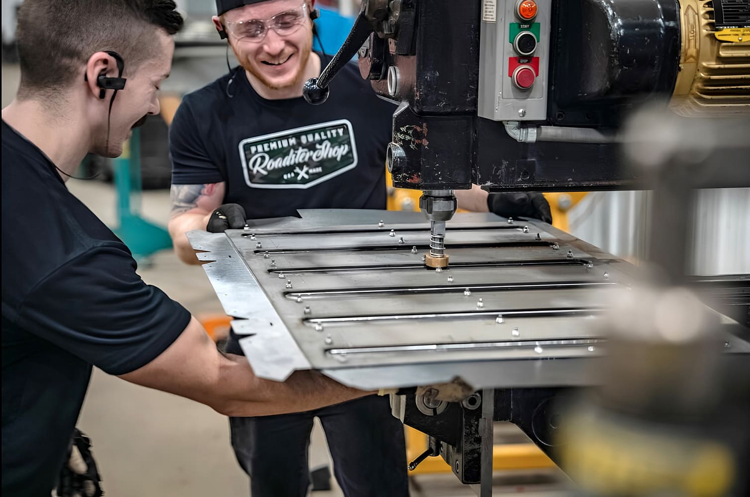
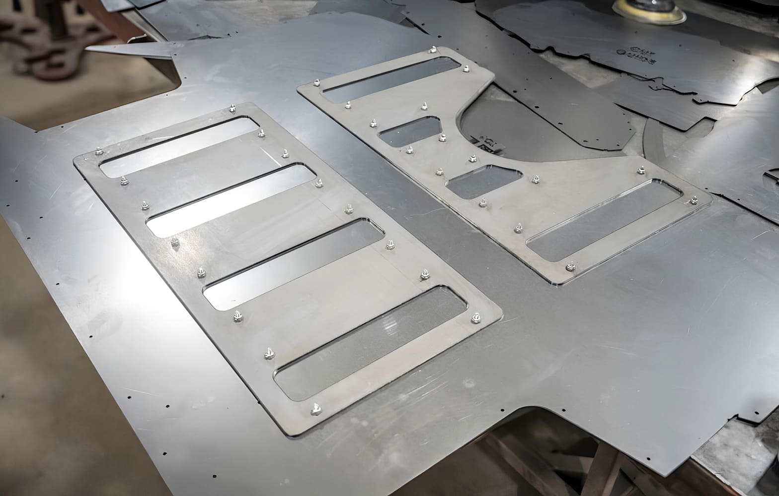
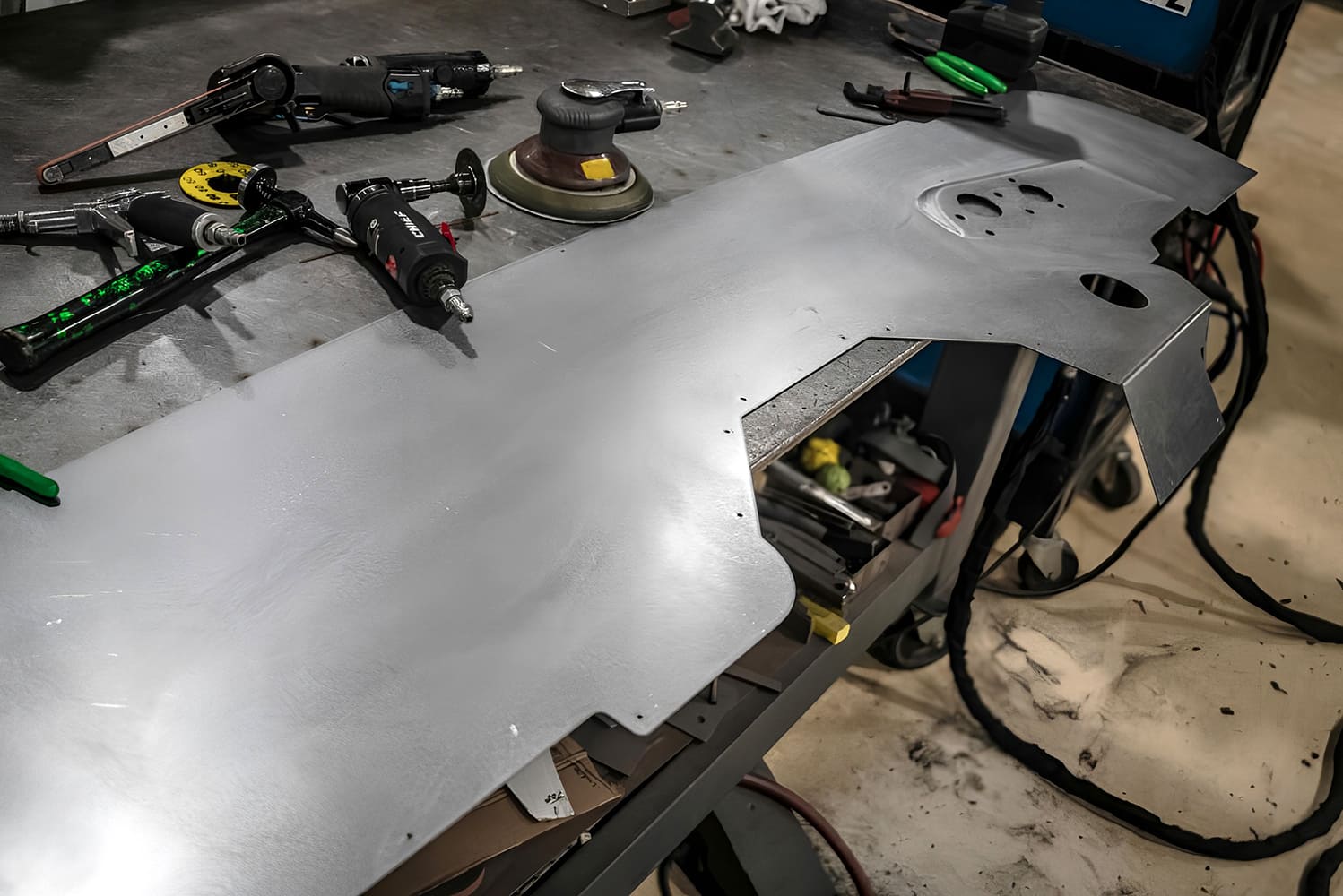
This digital information was also used to laser-cut guideplates to use on the Pullmax machine to precisely locate and form each rib. Some of the body mounts are located on the new floor, and these areas were heavily reinforced to provide the necessary strength.
The rear portion of the floor was cut out with a Sawzall.
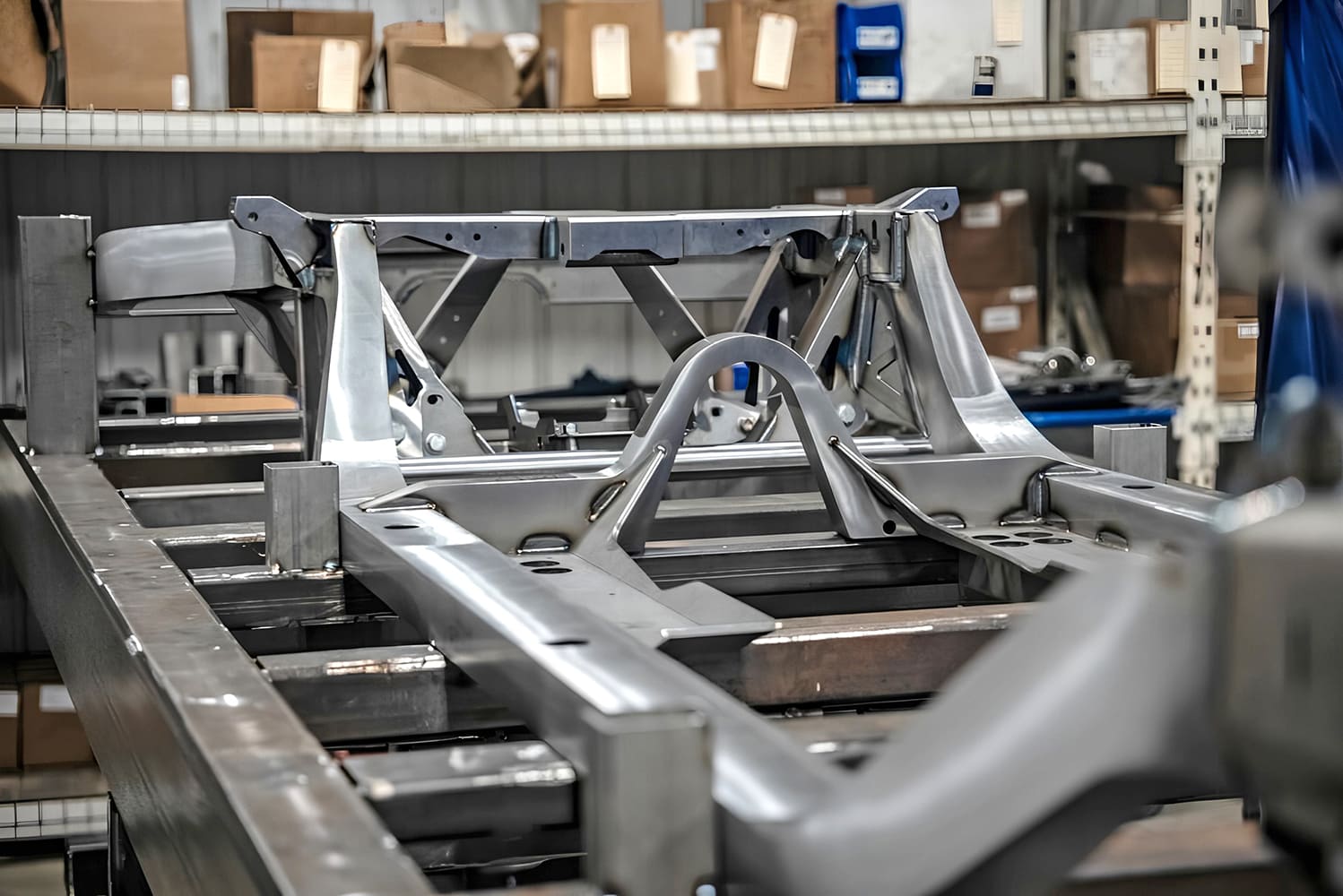
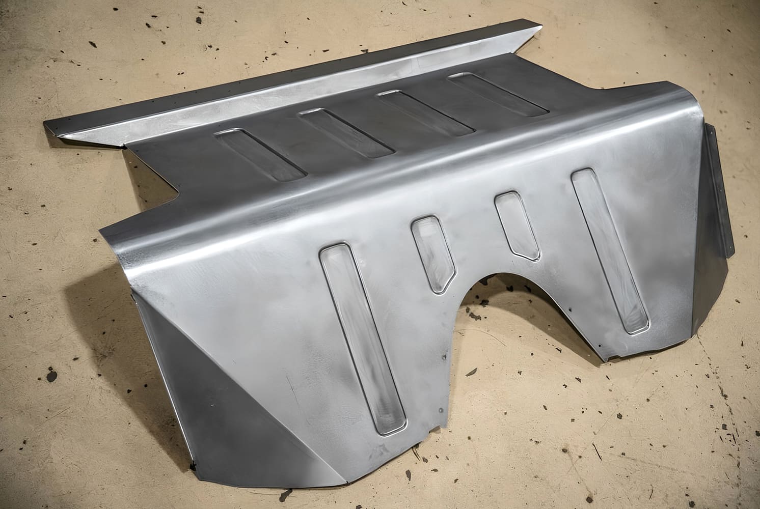
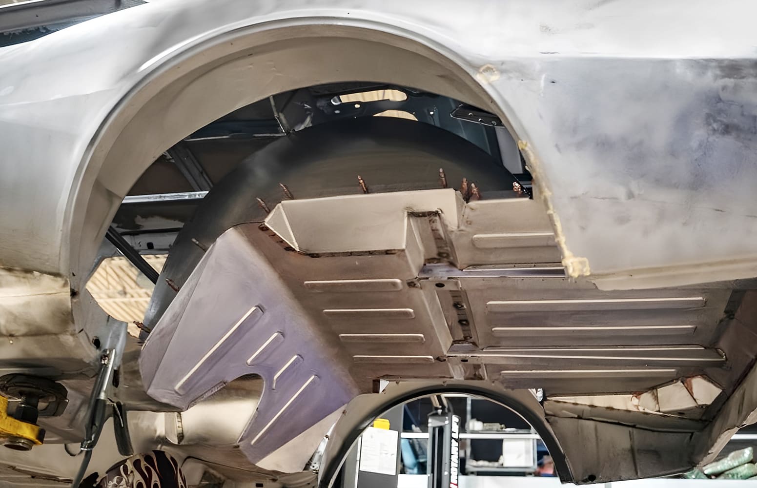
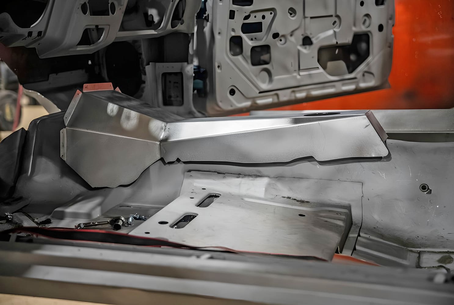
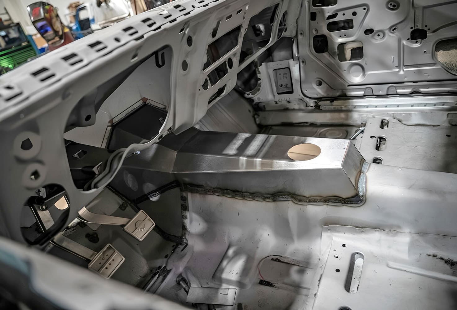
An arched crossmember was placed in the chassis just ahead of the independent rear suspension, so an extension was attached to the new floor panel to clear it.
The Roadster Shop Fast Track chassis is taller at the rear than the stock chassis to clear the independent rear suspension system. The new floor will be designed to clear the frame and connect solidly to the body.
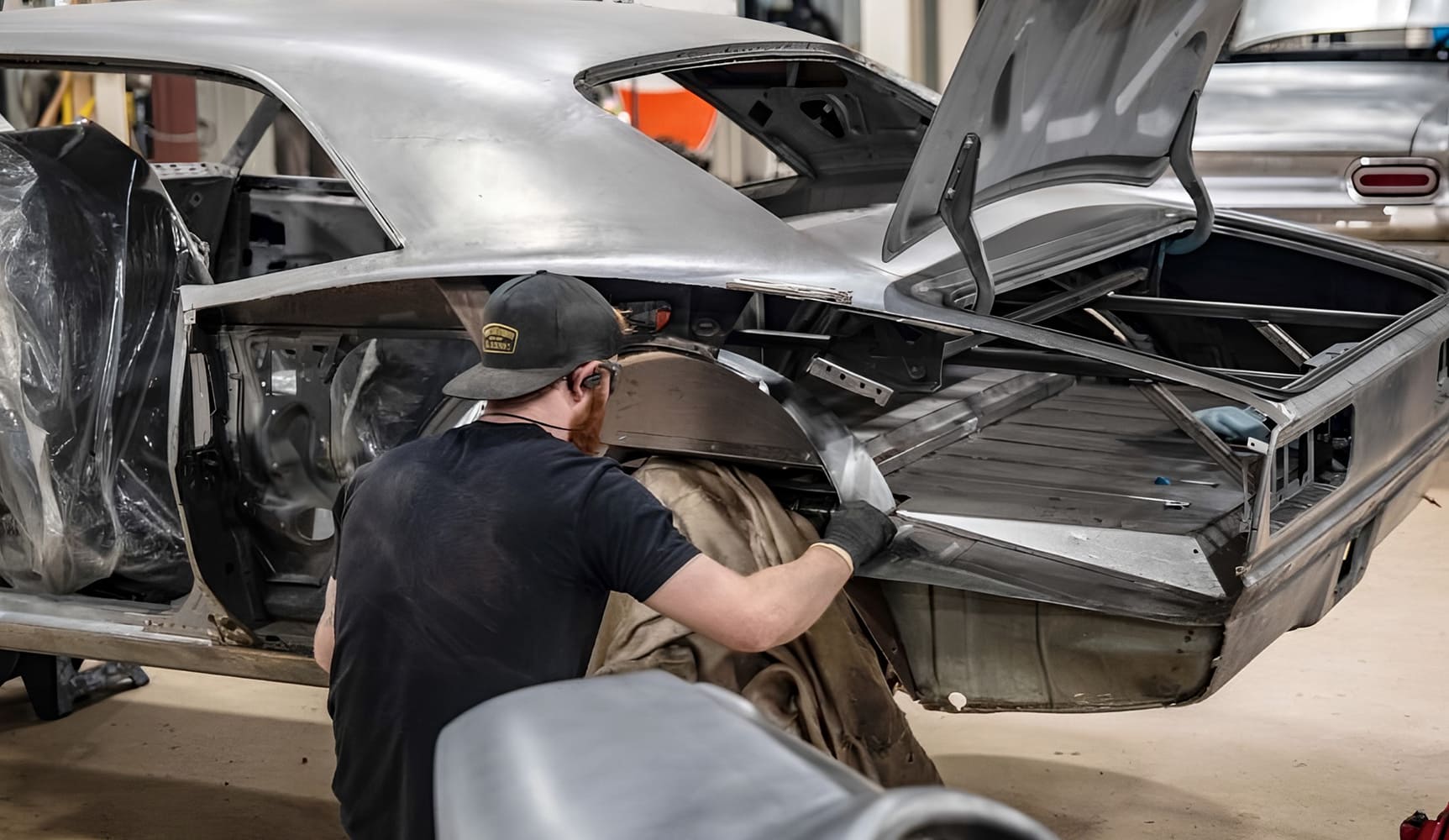
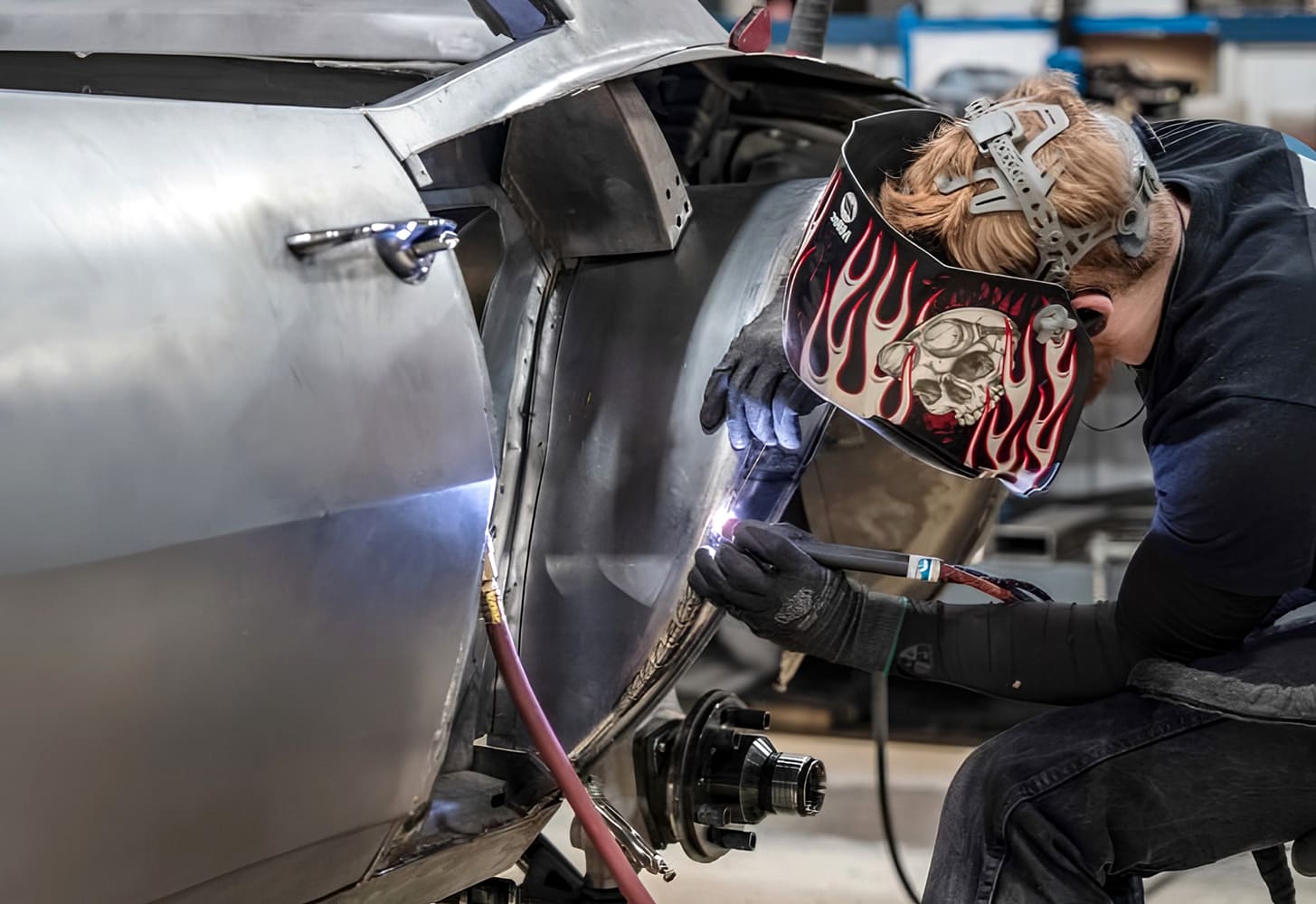
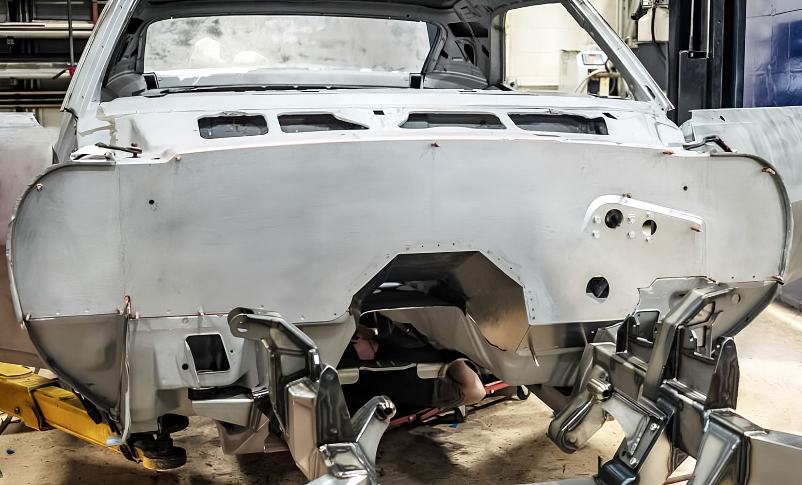
The rear wheelwells were enlarged to accept the wheels and tires selected for this car. Since aftermarket quarter-panels will be installed on this car, the original quarters were removed to provide access for working in this area.
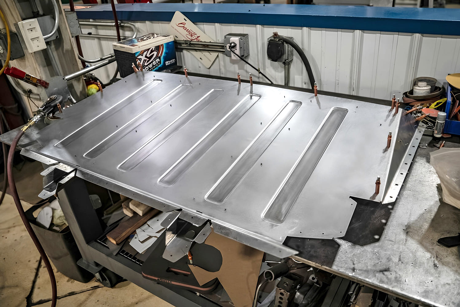
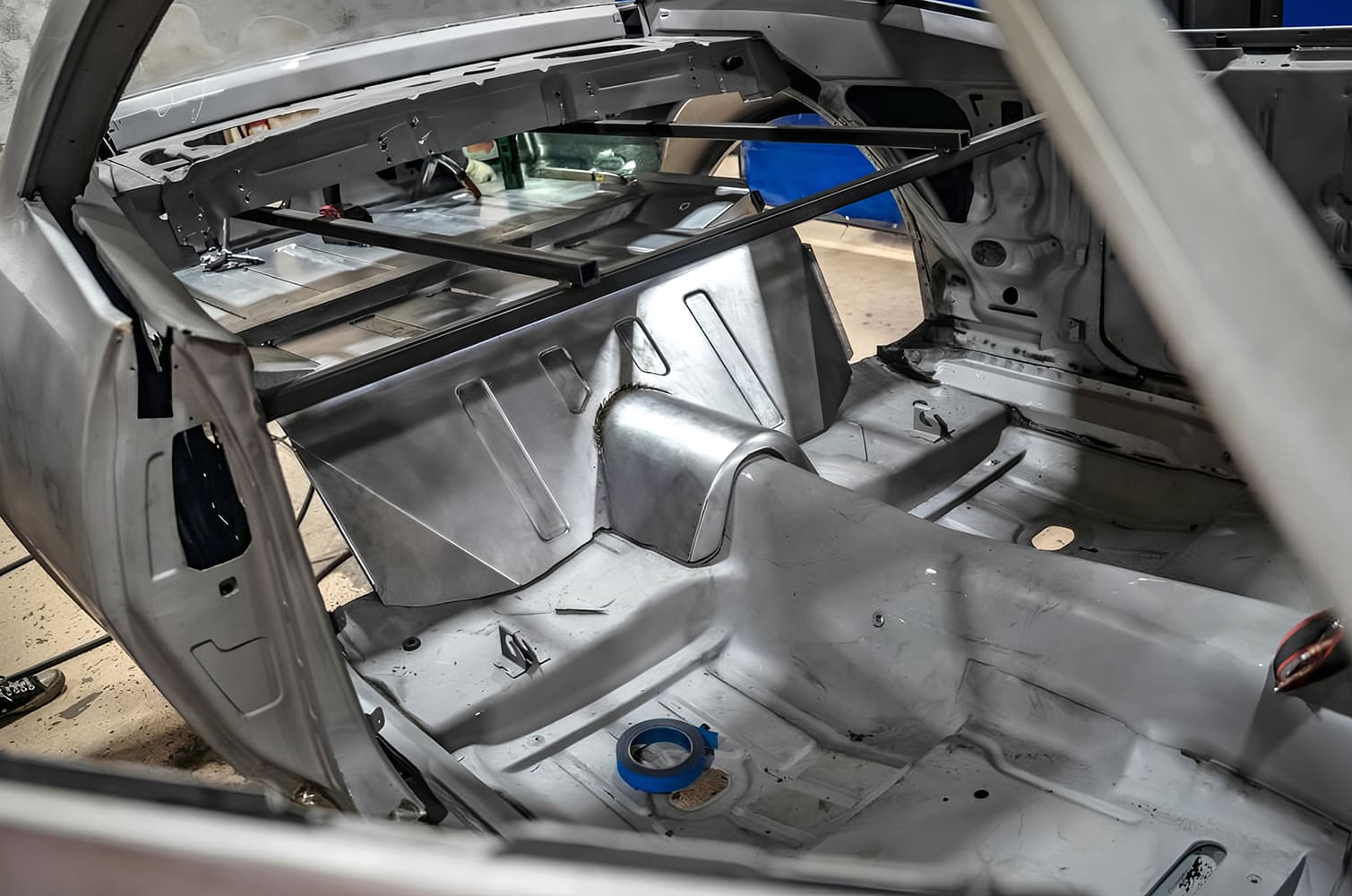
The new floor panels were designed in CAD, and tweaked until they fit both the body and the chassis perfectly. All of the stiffening ribs were designed and positioned at this stage, as well as all the flanges needed for mounting and for strength.
Extra clearance was needed for the shifter on the transmission, so a new sheetmetal construction was added to the top of the original transmission hump. This was CAD designed, laser cut, precision formed, and carefully TIG welded into place.
Templates were laser-cut to guide the panels in the Pullmax machine as the ribs are formed. The templates are being bolted temporarily into place here.
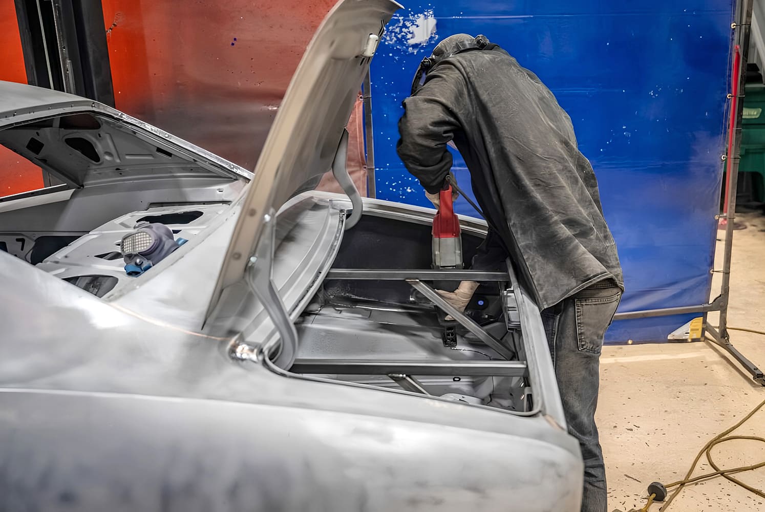
A new, smooth firewall was fabricated from heavy-gauge sheetmetal and was fitted to the cowl. This will give the car a much cleaner look when the hood is open.
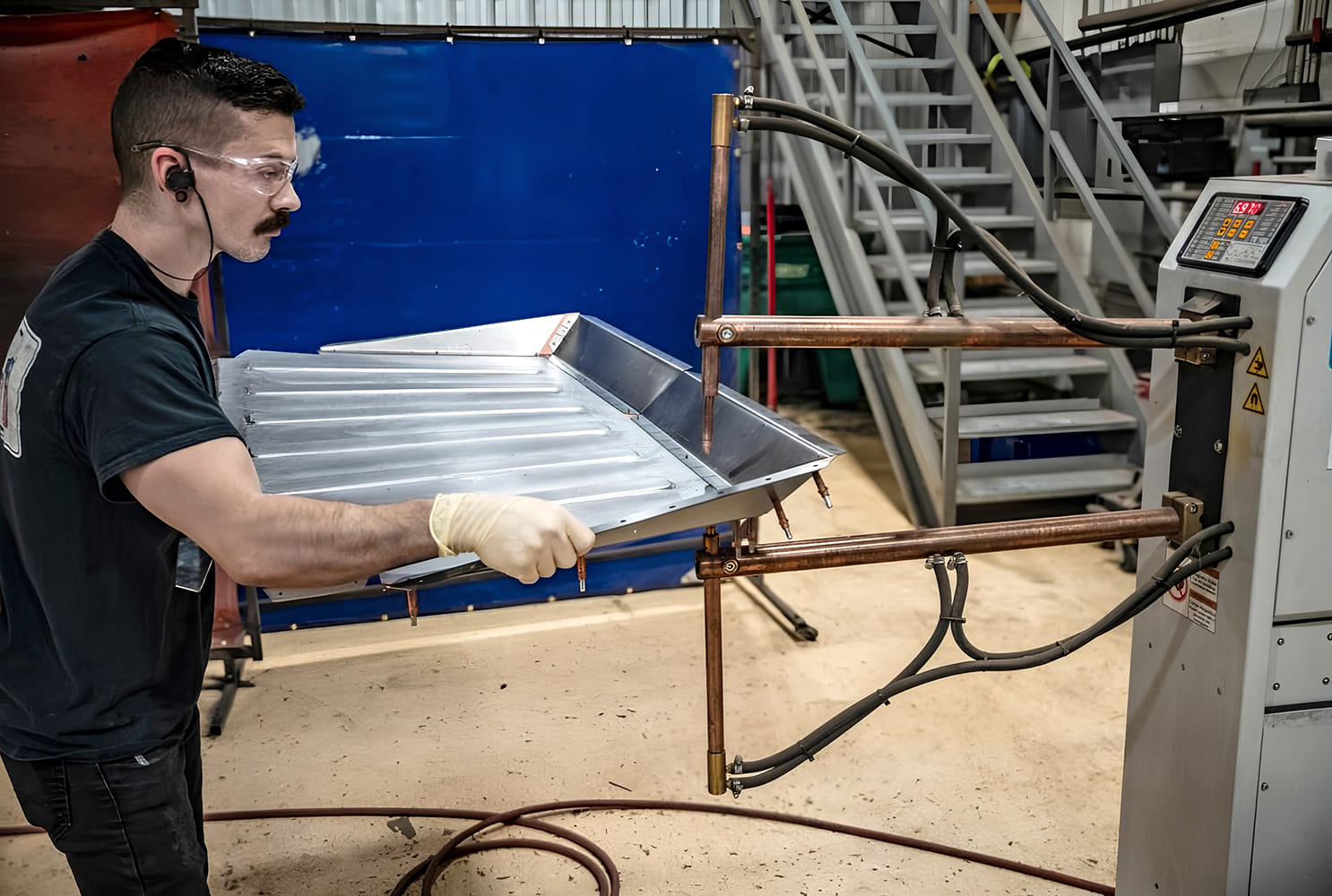
It’s a two-person job to guide large, heavy panels like this through the machine.
Lots more work is planned for this project, and next time we’ll look at how the wheelwell flares were designed and fitted to match the new wheels and tires. You may be surprised to see all the steps involved in this job, where lots of effort was expended to achieve a particular look.
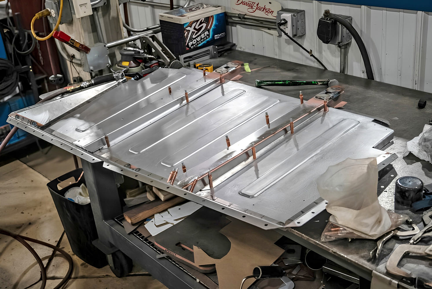
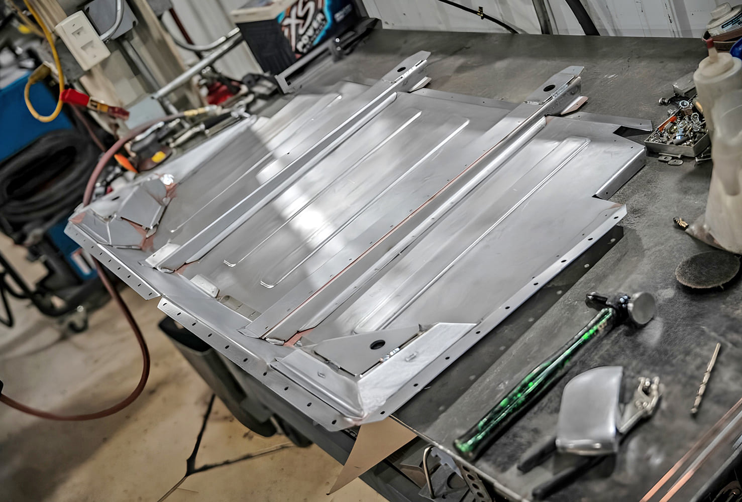
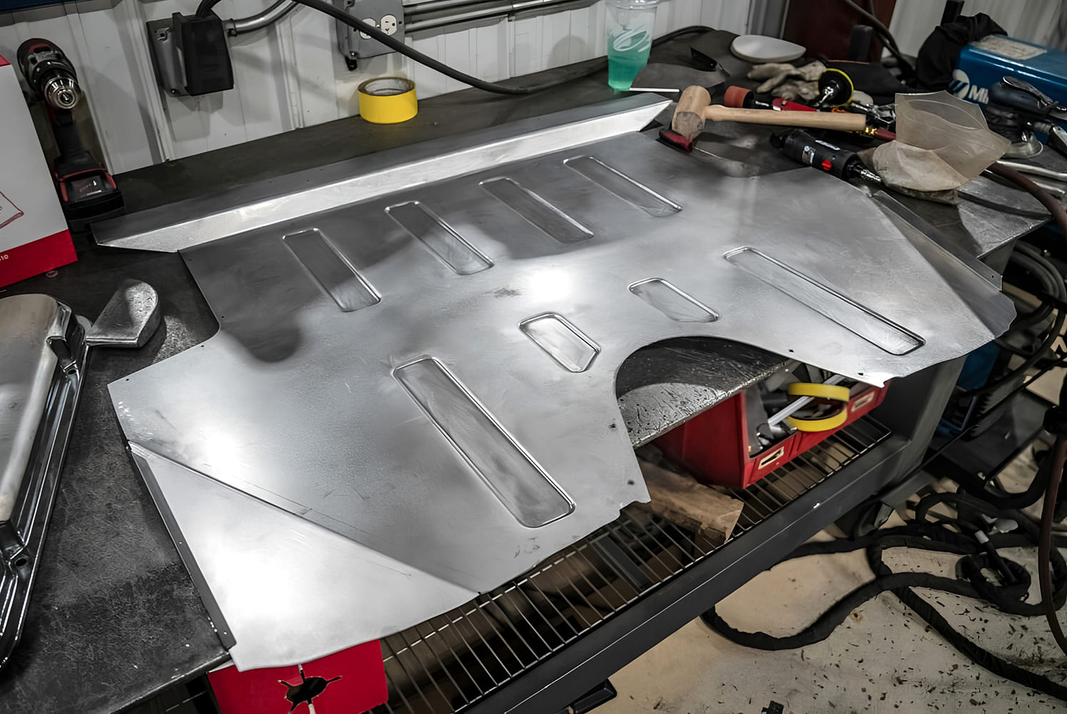
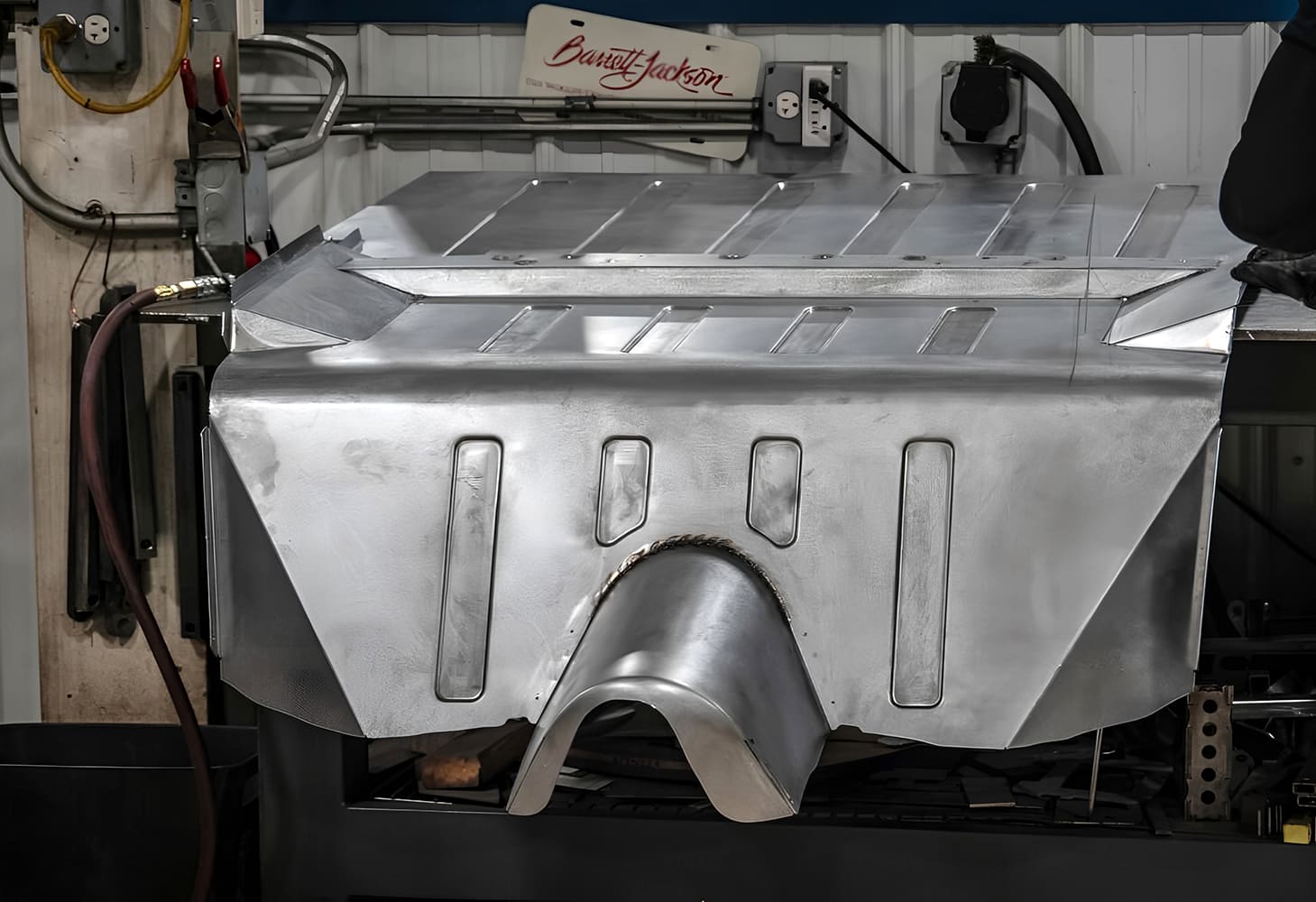
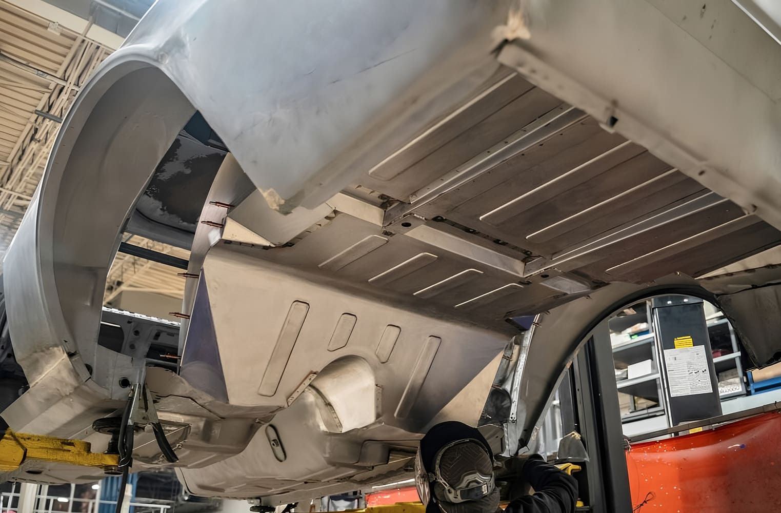
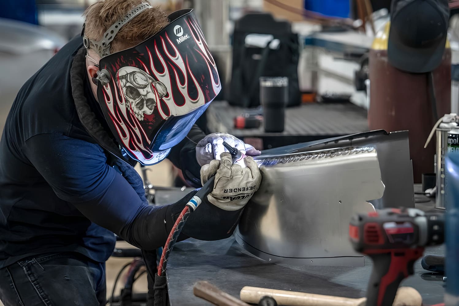
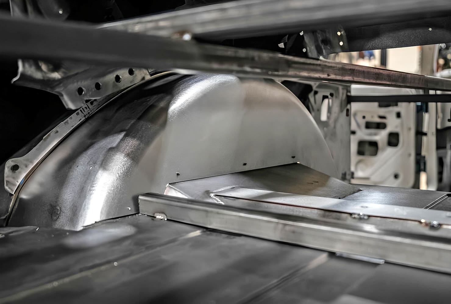
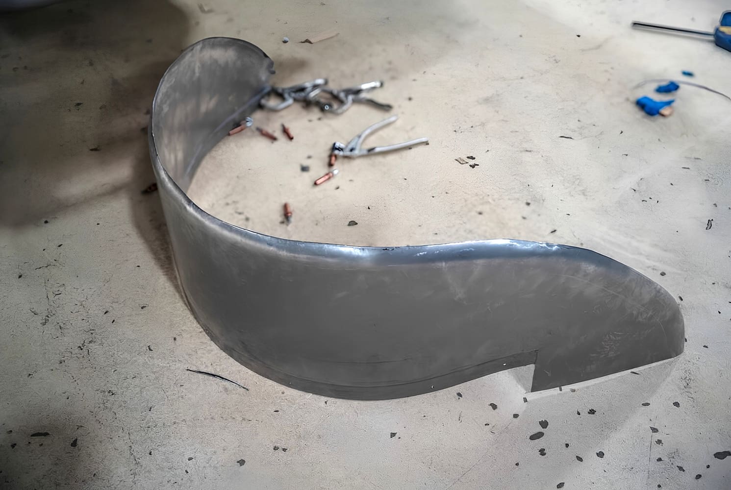
The guides must be held snugly against the edges of the tooling as the ribs are formed.Properly done, this process makes a very clean embossed rib, which adds considerable strength to the panel.Angled flanges were spot welded to the sides and rear edge of the largest panel.Reinforcements are added to the center of the panel to provide extra strength.Heavily reinforced body mounts are placed in the corners of this panel.Guides for the Pullmax are attached to the panel, which fits over the third member.The ribs have been fully formed, and a brake was used to make some bends in the panel.A brake with a radius die was used to form the rounded curve near the front of this panel.An extension is added to the front of this panel to go over the driveline and chassis crossmember.The floor panel is test-fitted inside the car.Looking up from the bottom you can see how perfectly all the components fit together.A flat piece of metal is held to the edge of the new floorpan with Clecos. This will be the inner face of the new wheelwell.Since the quarter-panels will be replaced with aftermarket units, they have been removed at this stage to gain access to the wheelwells. The top arch of the wheelwell is being fitted into place here.On the workbench, the components of the wheelwell are welded together.Clecos hold the new wheelwell in place as the fit is checked.The outer portion of the wheelwell is made as a separate piece.Here the new outer panel is being TIG-welded into place.A new cover was made for transmission, shifter, and bellhousing. It provides extra clearance where needed.Here the cover is welded to the original front floorpan.A new, flat firewall was fabricated from heavy-gauge sheetmetal.The firewall is held with Clecos as the fit is checked against the body. This clean, smooth firewall will really improve the appearance of the engine compartment.
We use cookies to ensure that we give you the best experience on our website. If you continue to use this site we will assume that you are happy with it.