
Rebuilding a Holley L88 Carburetor Service Replacement

By Brian Brennan – Photography By The Author

Whether we drive a stocker or a hot rod, we live in an increasing technology-driven era. Electronic fuel injection has become familiar because it delivers dependable idle quality, driveability, and performance from low rpm to the top of the tach. What more could a hot rodder want? Truthfully, EFI is the modern ideal.

But it’s time to pay homage to the carburetor. I must say that most of us, if not all of us, earned our “chops” on all sorts of carburetors—single-, two-, and four-barrel—across multiple applications on our favorite intake manifold. For me, the L88 Corvette V-8 from 1967-69 was the Holy Grail of V-8s, and the carburetor on top was “the” carb to have. Little did I know that both the Holley double-pumper and the intake were meant to be used together. I always wanted an L88 engine, but the real deal just isn’t going to happen. Building a “hot rodder’s version” is. But I am getting ahead of myself.
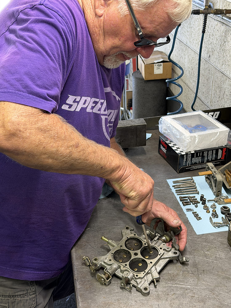
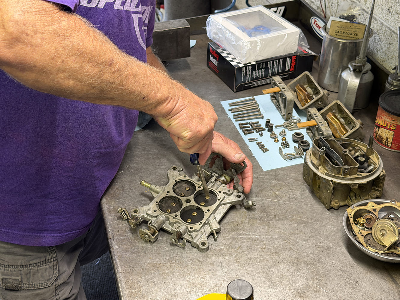
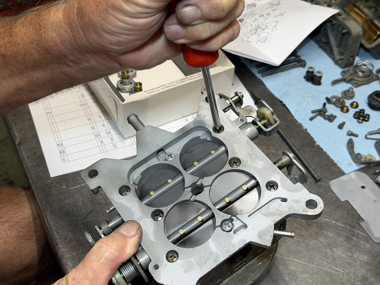
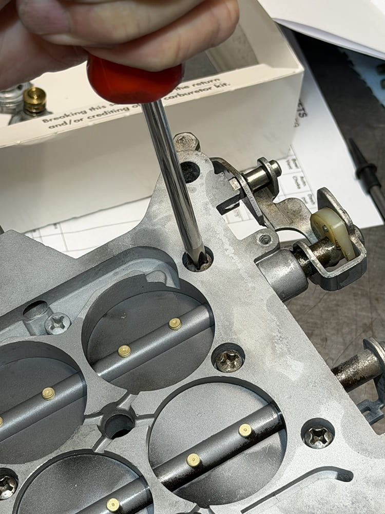
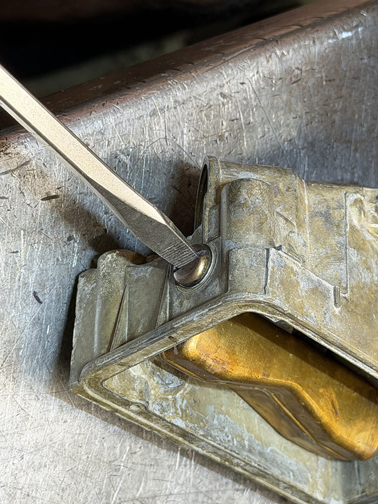
Carburetor technician using a flathead screwdriver to remove throttle plate screws from a Holley 4150 baseplate.
Before reassembly, Bob Kleiner, the ol’ carburetor wiz, verified that the throttle-blade screws were secure and that both blades closed cleanly, a small detail that helps prevent vacuum leaks and an erratic idle.

There are horsepower ratings and then there are horsepower ratings dreamed up by people who would rather not explain to the insurance industry, sanctioning bodies, or the fellow in the next lane exactly what they built. Chevrolet’s 1967-69 L88 Corvette was advertised at 430 hp, a figure widely recognized as grossly underrated. The 427-inch big-block had 12.5:1 compression, a solid-lifter cam, aluminum heads, and an aluminum intake, intended for heavy throttle and race fuel. Hot rodders from that era can attest to the original L88’s power output and will gladly recall the eye-popping numbers and on-track performance. A well-tuned L88 outputs well above the advertised figure, often in the 500-plus-horsepower range, although the exact number depends on numerous external factors.

Sitting atop that controlled explosion was a Holley four-barrel, too often reduced to a single phrase: “the L88 carb.” That shorthand misses the point. Chevrolet used three distinct Holley configurations during the L88’s brief production life, and each tells us something about how the engineers refined the package. The carburetor I found through a well-versed Chevrolet engineering guru friend also adds a fourth chapter—the service-replacement piece that carried L88 hardware beyond the assembly line.
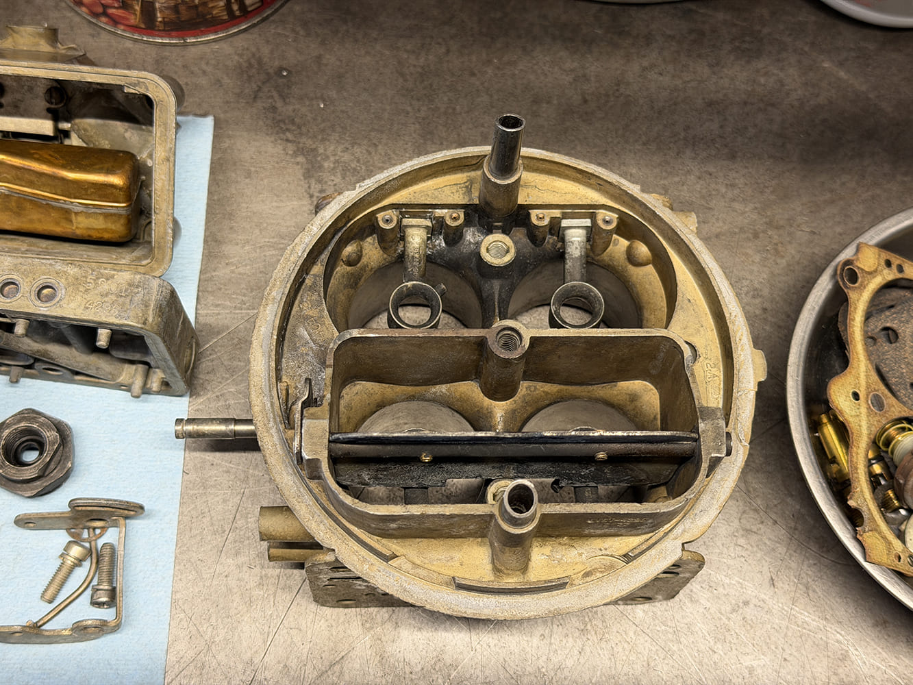
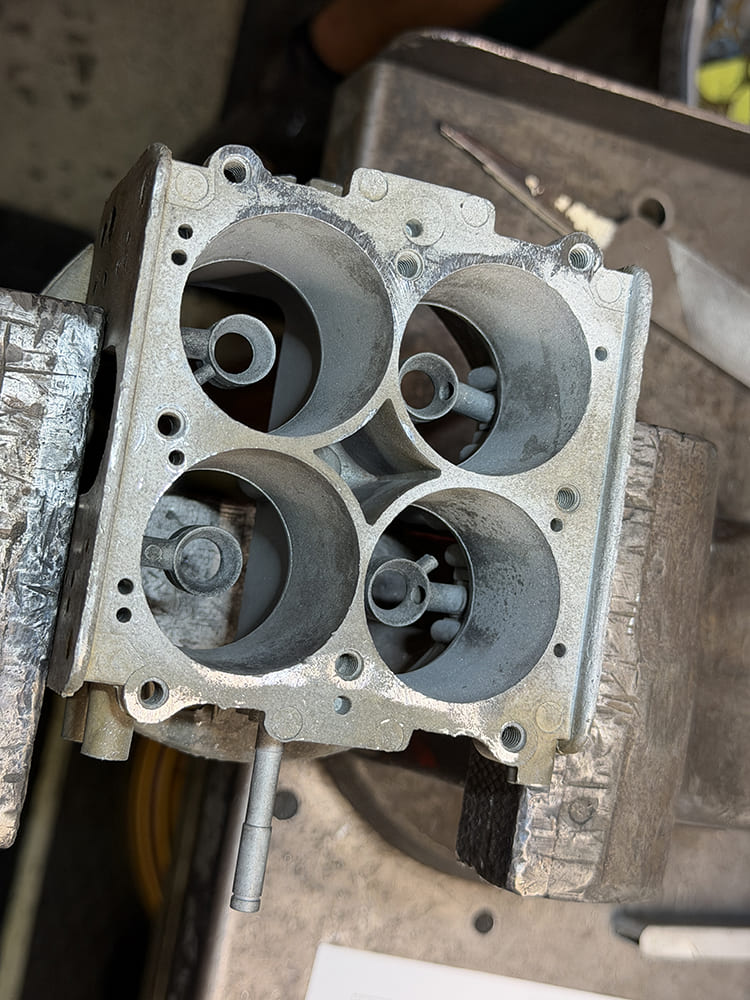
Top view into the main body of a vintage Holley 4150 carburetor showing down-leg booster venturis and choke horn assembly.
The main body was cleaned, inspected, and prepared for assembly, while the magnetic tray kept worn hardware organized for replacement with new components during final assembly.

I came across the carburetor through a longtime Chevy hot rodder and collector of serious high-performance parts. (It had hung on his garage wall since the late ’70s, along with a Winters big-block Chevy intake.) The air horn stamping and the 850-cfm 4150 architecture immediately suggested valuable territory. I had already “borrowed” the correct intake (yep, that Winters) from Dean Livermore of Hot Rods by Dean—he was still speaking to me at press time—for a tribute L88 build I had wanted since my late high school/early college days. Owning a real L88 Corvette would require more money than this editor has ever seen in one place, but building a faithful big-block tribute seemed just irresponsible enough to be achievable.

The carburetor needed someone who understood old Holleys as hardware, not folklore, so I called fellow Arizona hot rodder Bob Kleiner. Kaiser Bob is known for all kinds of mechanical wizardry and is especially sharp on Ford hardware, which naturally makes him the perfect man to rebuild a rare Chevrolet carburetor. More importantly, he is the best carb man I know. That skill is becoming so scarce it qualifies as its own endangered species. Kleiner studied the casting, dug into his vintage Holley manuals (yes, those old, printed catalogs and manuals many of us have hung onto for decades) and parts catalogs, and confirmed that we were dealing with the family of carburetors that fed Chevrolet’s most notorious production big-block. We rounded up a JEGS Holley rebuild kit (PN 510-37-485).
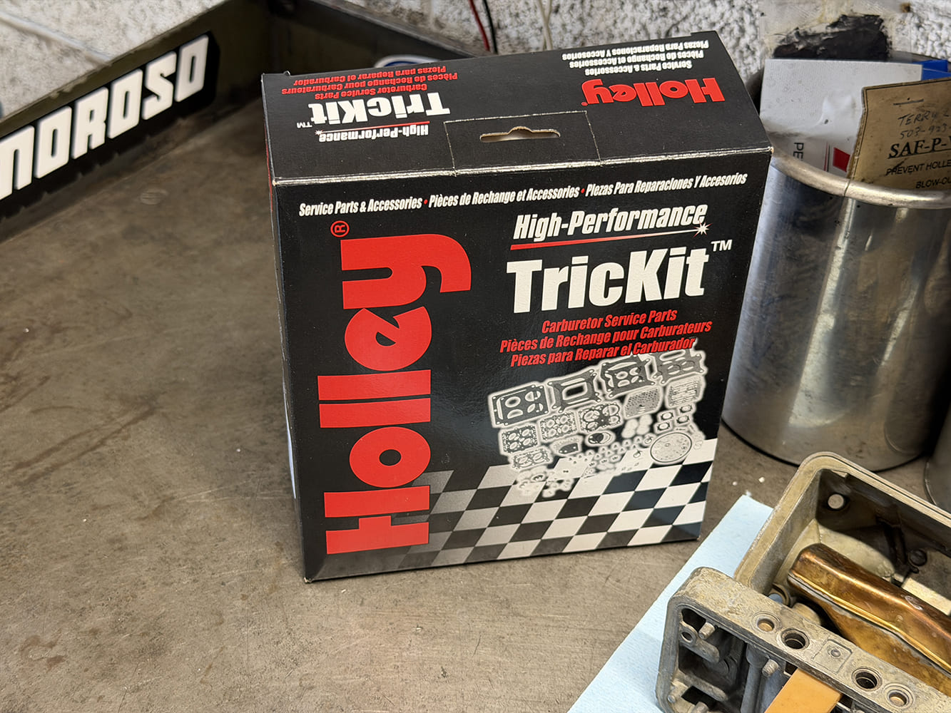
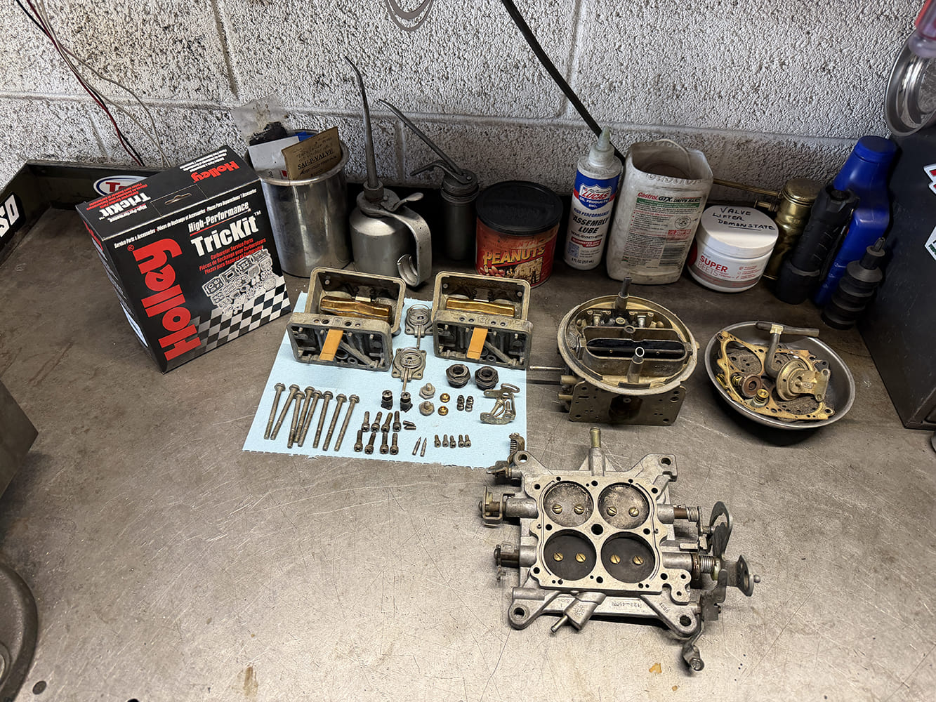
Box for a Holley TrickKit high-performance carburetor rebuild service kit containing replacement gaskets and performance parts.
The Holley rebuild kit provides the new gaskets, seals, and service components needed to reassemble the L88 carburetor correctly after thorough cleaning and careful inspection.

That was the moment this stopped being merely a rebuild and became mechanical archaeology. You can clean a common Holley, fit it with fresh gaskets, adjust it, and send it back to work. An L88 Holley deserves a slower approach because the stampings, metering blocks, boosters, linkage, bowls, baseplate, pump hardware, and original finish all contribute evidence. The job is not to turn a rare old carburetor into a shiny universal replacement. The job is to restore its fuel metering, sealing, throttle action, and accelerator-pump operation without erasing the details that tell us what it is.

Three Holleys, One Race-Bred Mission

The story begins in 1967 with the Holley List 3418/3418-1, Chevrolet PN 3886091-AN. It was a dual-feed 4150 generally identified in restoration references as an approximately 850- to 855-cfm carburetor with vacuum-operated secondaries. Published specifications also commonly list 1-9/16-inch venturis and 1-3/4-inch throttle bores, but verify jetting, pump-nozzle size, metering-block orientation, and revision details against an original Holley numerical listing or an authenticated, unmodified carburetor before publication. That caution matters because the 3418 is sometimes casually called a double-pumper. Surviving examples and application references identify it as a vacuum-secondary carburetor calibrated for the first-year L88, and a correct main-body number alone cannot make later bowls, blocks, boosters, linkage, or baseplate authentic.

For 1968 and into the first 1969 design, Chevrolet turned to the Holley R-4054A, GM 3925519, another vacuum-secondary 4150. Documented clues include 5247 primary and 5253 secondary metering blocks. Most Corvette references place it in the same general 850-cfm neighborhood as the 3418, although a current Holley listing gives a much-lower 570-cfm figure. That discrepancy is worth acknowledging rather than sanding it smooth. Old performance hardware often arrives with conflicting catalogs, superseded service data, and decades of confident bench racing attached.
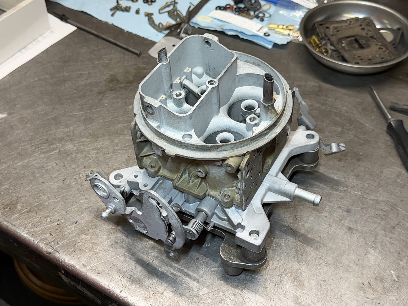
Refreshed Holley 4150 850 CFM carburetor center section with baseplate mounted and mechanical secondary linkage installed.
With the throttle body and main body joined, the carburetor rests securely on its stand, ready for power valves, metering blocks, fuel bowls, and linkage.

Later in the 1969 model year, the version most hot rodders picture when someone says “L88 Holley” arrived: the List 4296/R-4296A, Chevrolet number 3955205. This was an 850-cfm 4150 with mechanical secondaries and accelerator pumps on both float bowls—the genuine double-pumper arrangement. It carried 1-9/16-inch venturis, 1-3/4-inch throttle bores, 78/82 baseline jetting, and 0.035-inch pump nozzles. Documented internal identifiers include a 5895 primary metering block and a 5901 secondary block, and the 12R-4507B throttle-base casting matches known 4296 assemblies. The carburetor also served the closely related all-aluminum ZL1 427.
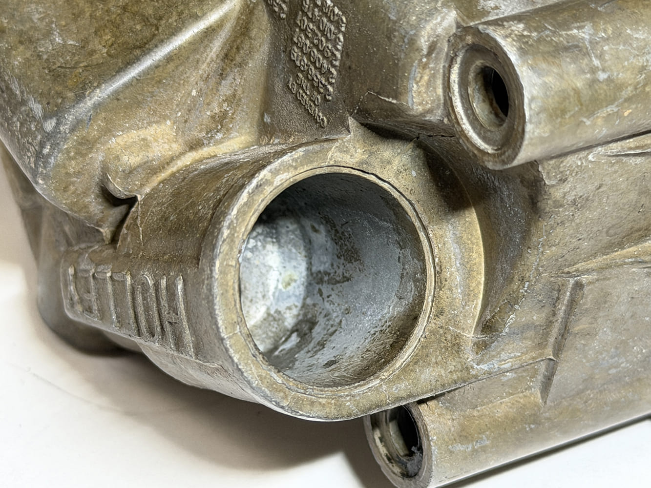
Macro view of the cavity and stamped Holley brand lettering on a vintage carburetor fuel bowl.
This unused fuel-inlet port is sealed with the appropriate threaded plug, preventing leaks while preserving the option to route the fuel supply from either side.

The change from vacuum to mechanical secondaries was more than a simple number swap. A mechanical-secondary 850 opens the rear throttles in direct response to the linkage, and the second accelerator pump delivers an immediate shot of fuel to cover the sudden increase in airflow. On a 12.5:1, solid-lifter 427 intended to live upstairs on the tach, response mattered. One period-specific detail is the smaller 30cc secondary accelerator pump, rather than the 50cc unit familiar on many later performance 850s. That is exactly the sort of unglamorous little part that separates a correctly restored application carburetor from a generic double-pumper wearing an impressive stamp.

The 850-cfm rating was not an extravagance. Using the standard airflow calculation, a 427 consumes roughly 741 cfm at 6,000 rpm at 100 percent volumetric efficiency and about 865 cfm at 7,000 rpm. A race-developed engine can also exceed 100 percent volumetric efficiency in its sweet spot. Chevrolet sized the carburetor for the engine it actually built, not for the 430hp number printed in sales literature. When the secondaries opened and the solid lifters were working, the L88 needed every bit of breathing room the Holley could provide.
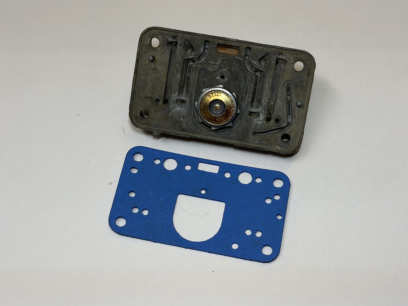
Blue non-stick Holley metering block-to-main-body gasket displayed beside the back side of an assembled metering block.
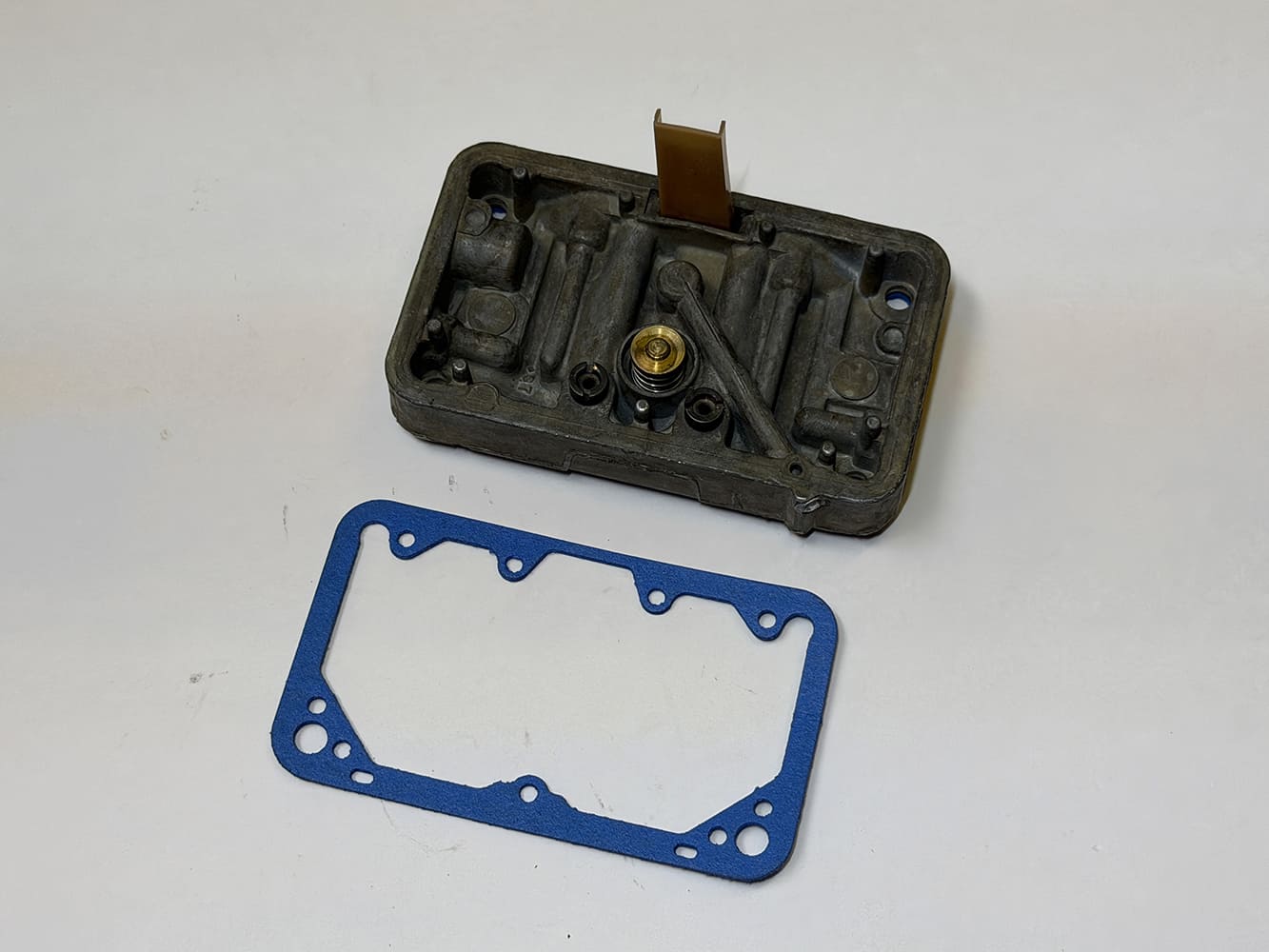
The fresh metering-block gasket aligns with all fuel and air passages, creating the necessary seal while allowing each calibrated circuit to communicate with the main body.
The Intake Changed the Rules

The L88’s Winters cast-aluminum intake (thanks to my buddies Scotty and Dean, who bagged this intake and took it home, sort of) shows why you can’t judge these carburetors by airflow alone. It was a high-rise, dual-plane manifold with part of the plenum divider removed to improve high-rpm breathing. That modification also altered the paths the mixture took from the four throttle bores to the cylinders. Because demand was not perfectly symmetrical, Chevrolet and Holley treated the intake and carburetor as a matched system.

Staggered jetting, application-specific metering, and booster fuel-distribution tabs helped compensate for those unequal paths. The tabs may look odd alongside a modern performance booster, but they are not casting debris or an invitation to “improve” the carburetor with a grinder. Their shape is part of the original distribution strategy. Replacing them because a newer design looks cleaner may earn bragging rights but lose the very calibration that made the L88 package work.

Identification therefore follows a chain. The Chevrolet number ties the assembly to an application. The Holley list number identifies the basic carburetor. Metering-block and baseplate numbers reveal what is actually inside and underneath. Patent numbers are useful supporting evidence for the casting technology, but they say “Holley” not “L88.” A restamped main body cannot make incorrect metering blocks, bowls, boosters, or linkage original.

Date codes are where our carburetor becomes especially interesting. Pre-1973 Holleys typically used a three-digit code: the first digit represents the year, the second the month, and the third the week. For example, a 951 stamp corresponds to the first week of May 1969. A 022 code indicates a year ending in zero, February, and the second week. In the context of an L88-specification carburetor, that points plausibly to February 1970 and suggests an early service replacement rather than an assembly-line-installed 1967 piece.
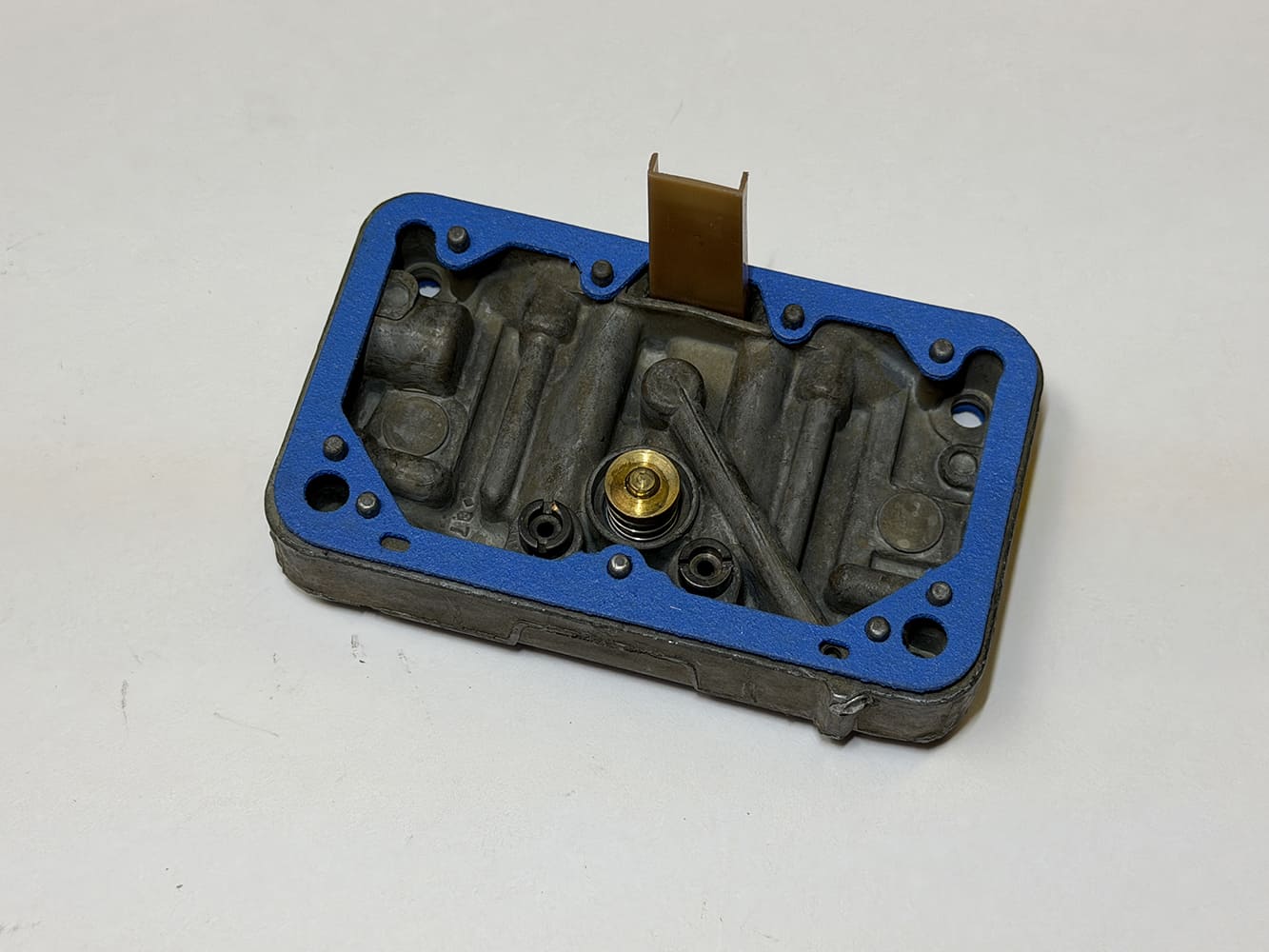
Blue non-stick fuel bowl perimeter gasket fitted onto the outer sealing edge of a Holley carburetor metering block.
The fuel bowl is seated against the new gasket and metering block, creating a leak-free joint while maintaining alignment of the internal fuel passages.

Later service carburetors may use a four-digit format. In a stamp such as 2577, the first three digits identify the Julian day, and the last digit indicates a year ending in seven. Day 257 falls around September 14. Without additional manufacturing evidence, that final digit could apply to more than one decade, so it would be reckless to state a single year as certain. The format does tell us, however, that the carburetor is not wearing a normal 1969 assembly-line date. It is best described as a List 4296 L88/ZL1-specification service or replacement carburetor unless the remaining hardware establishes something more specific. (In our case, the jets and power valves matched the true L88 sizing.)

That distinction does not make it an impostor. Chevrolet dealers and Holley had to support engines after the original cars left St. Louis, and service carburetors carried the correct functional design into later years. For a concours Corvette, the calendar matters enormously. For a period-correct hot rod or our tribute L88, a genuine service 4296 can be exactly the right piece: authentic engineering, correct basic calibration, and a history that extends beyond production.
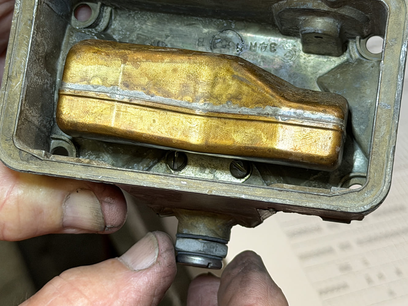
Checking clearance and dry float level of the brass fuel float inside an inverted Holley 4150 fuel bowl.
The float level is adjusted via the needle-and-seat nut, then secured with the locking screw to maintain a consistent fuel level under operating conditions.
Rebuild the Evidence, Not Just the Carb

Before Bob turned the first screw, we photographed the choke tower, including both sides, both bowls, linkage, accelerator-pump arms, boosters, air bleeds, metering blocks, baseplate, and the underside. We recorded the list number, Chevrolet number, date stamp, and every casting number we could find. This is not busywork. Solvent can make a faint stamp harder to read, blasting can wipe away the original finish and machining evidence, and 50 years of screwdriver scars can obscure an otherwise useful clue. Once that history is gone, no renewal kit can restore it.

Disassembly should be just as disciplined. Keep primary and secondary parts separate, record jet positions, and compare each gasket to its replacement before anything goes in the trash. On a 4296, the 5895 front and 5901 rear metering blocks (which we have) deserve close attention, as do the two 0.035-inch discharge nozzles, the dual pump circuits, the mechanical-secondary linkage, and the 12R-4507B baseplate. The 78/82 jet combination is a useful, documented baseline when you retain the original calibration, but the parts in front of you and reliable period information outweigh whatever somebody typed on a message board 20 years ago.

Cleaning is straightforward in principle but unforgiving in practice. Every fuel and air passage must be clear. Metering surfaces must be flat, throttle shafts must move freely without excessive wear, and the throttle blades must close without binding in the bores. Check the 1-9/16-inch venturis and 1-3/4-inch throttle bores for undocumented modifications. Bob also inspects the needles and seats, power-valve components, floats, pump diaphragms, check valves, discharge nozzles, and pump cams. A Holley 37-487 Renew Kit supplies the expected service parts, but a generic pile of 4150 parts is not permission to overwrite application-specific hardware.
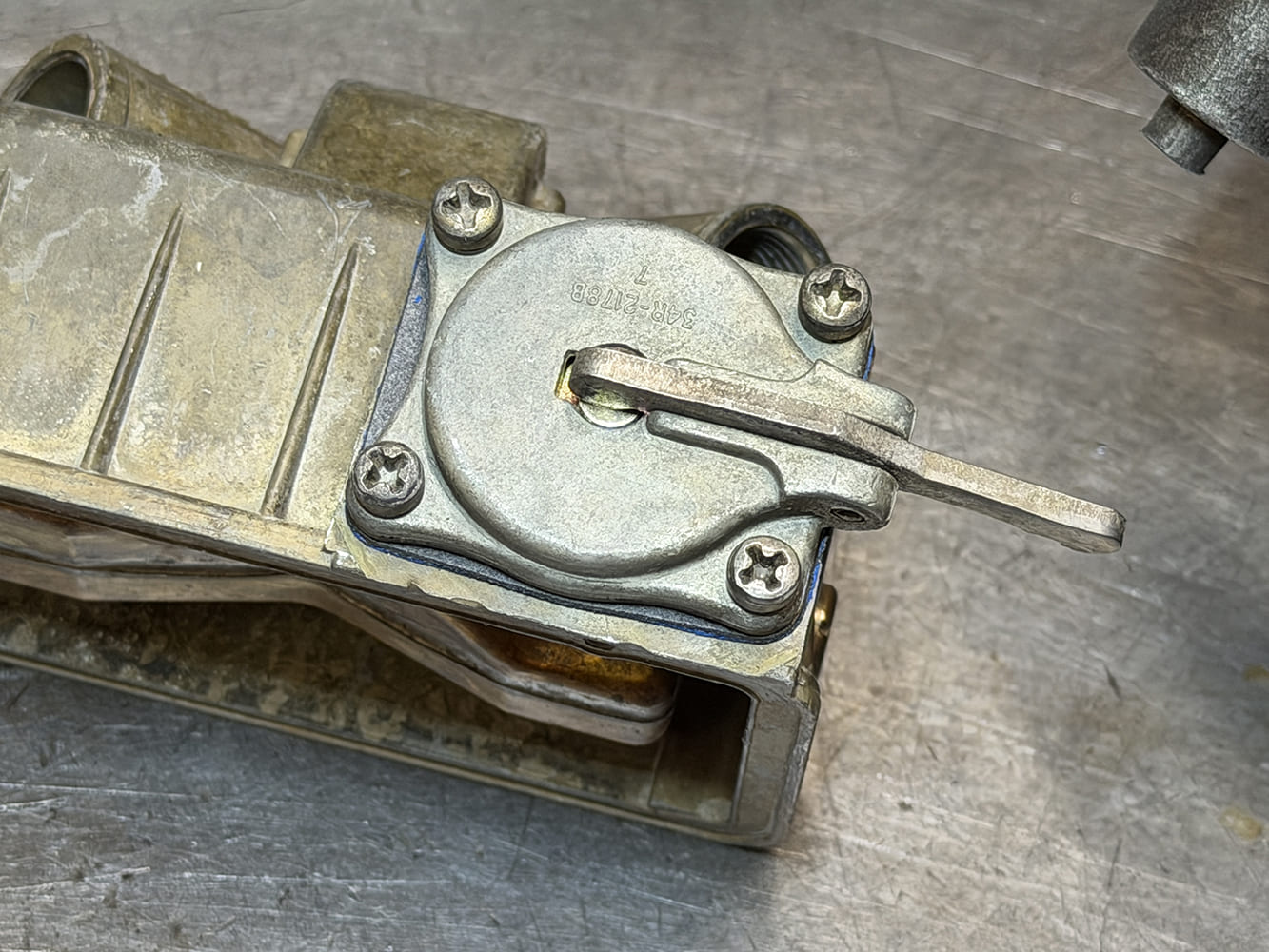
Underside view of a Holley carburetor fuel bowl with the accelerator pump cover, diaphragm, spring, and actuating arm bolted in place.
The accelerator-pump cover is installed over the diaphragm and return spring, securing the assembly while maintaining the sealed chamber required for consistent pump-shot volume.

Reassembly is where patience earns its keep— Kleiner’s forte. The correct gasket must sit under each metering block and bowl. The floats need a safe initial setting, and the accelerator-pump lever clearance must remain correct throughout the full throttle sweep. Both pumps should deliver fuel immediately when the throttle moves—no dead stroke, no lazy dribble, and no linkage binding before wide-open throttle. The rear blades must reach full travel, but the mechanism should not be forced against its stops.

The photo sequence and captions address the bench details step by step. The text has a different job: explaining why those details matter. A rare Holley is more than its list number, and a correct rebuild is more than just making the bowls stop leaking. The air horn stamping, GM number, date code, metering blocks, boosters, baseplate, pump hardware, and finish must tell a consistent story. If they do not, the carburetor may still be an excellent runner, but it should not be presented as an untouched assembly-line original.
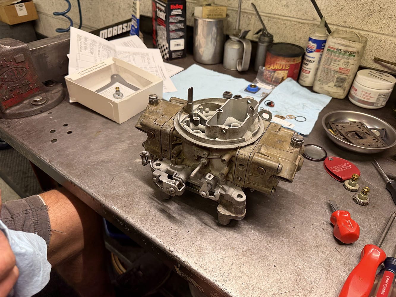
Fully reassembled vintage Holley 4150 four-barrel carburetor sitting on a stainless steel shop bench surrounded by tools and rebuild supplies
Both fuel bowls are assembled against their metering blocks with fresh gaskets, completing the primary and secondary fuel reservoirs while sealing every corresponding fuel passage.

For our purposes, the carburetor’s service-replaceability makes it more interesting, not less. It connects the brief, expensive, race-first L88 program with the practical world of dealership parts counters and hot rodders who kept these engines alive. It also gives us a period Holley we can rebuild and run without pretending every scratch came from a Corvette assembly worker in 1969.

When done correctly, as Kleiner has done, the carburetor looks familiar rather than over-restored, runs cleanly, and preserves the distinctive details engineered into it more than half a century ago. Then comes the moment every carb story is really waiting for: bolting it to that Winters-style intake, setting it over the tribute 427, and pulling the handle on the dyno. For me, it will be a trip back to the days when I could only read about the L88 and wonder why Chevrolet thought so highly of an engine it rated at just 430 hp.

Now we know. The number was modest. The hardware was not. And when an 850-cfm L88 Holley opens all four barrels on a solid-lifter 427, the engine has a wonderfully direct way to set the record straight. MR
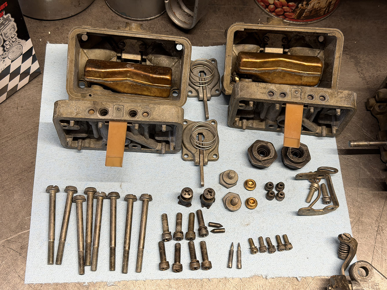
Fuel bowls with brass floats, accelerator pump housings, metering blocks, and assembly screws for a Holley 4150 rebuild.
Close inspection of the fuel bowls, metering blocks, and fasteners confirmed that each part was clean and serviceable before the throttle body assembly proceeded to final reassembly.


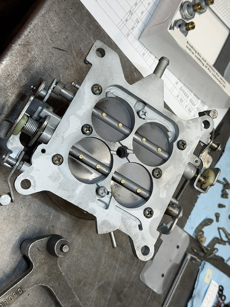
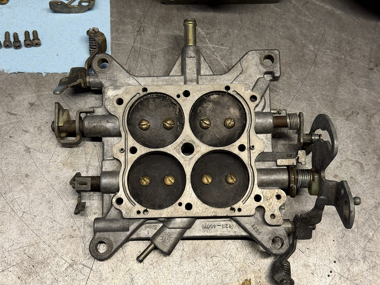
Overhead view of a Holley 4150 850 CFM carburetor cast baseplate showing four throttle butterfly valves and mechanical linkage.
Cleaned and carefully inspected, the throttle body assembly is ready for reassembly, with the throttle bores, shafts, and linkage checked for smooth, bind-free operation throughout their travel.


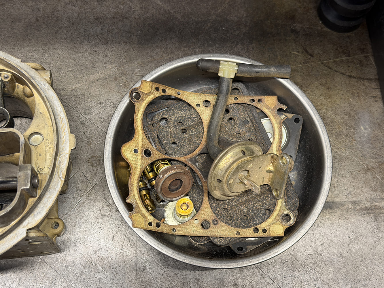
Stainless steel parts tray filled with old metering block gaskets, needle and seat assemblies, and vacuum diaphragms.
The magnetic parts tray keeps discarded hardware contained and clearly separated from the cleaned components, preventing worn fasteners and small pieces from returning during final assembly.


Technician rebuilding a Holley 4150 carburetor baseplate on a shop bench using a screwdriver to align butterfly plates.
This repeated opening view provides another look at the complete L88 Holley before assembly work begins, establishing the carburetor’s original configuration for reference during the rebuild.


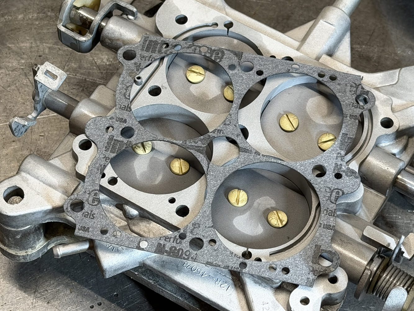
New non-stick baseplate-to-main-body gasket aligned over the throttle bores of an ultrasonic-cleaned Holley baseplate.
After cleaning and inspection, the throttle body receives a new gasket, providing the flat, reliable seal needed where it mates with the carburetor’s main body.


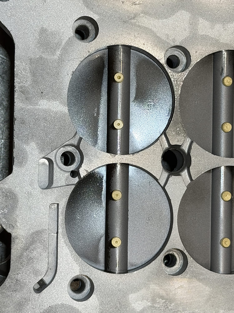
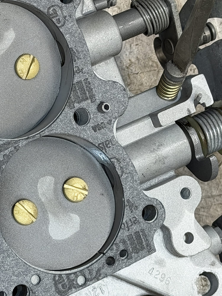
Underside close-up of throttle plates centered and secured with brass screws inside the throttle bores of a Holley baseplate.
From below, the cleaned throttle body reveals the throttle plates, bores, and mounting surfaces, all of which must remain clean, aligned, and undamaged before assembly.


Adjusting the idle speed stop screw and return spring on the throttle linkage of a Holley 4150 baseplate.
Each throttle plate is adjusted within its bore to close evenly without binding, helping maintain consistent airflow and predictable idle quality once the carburetor is running.


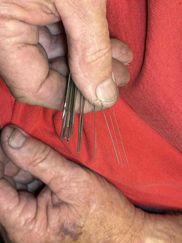
Hands holding a set of fine wire cleaning broaches used to clean carburetor air bleeds and fuel orifices.
Compressed air verifies that the internal passages are clean and open, an essential check because restricted passages can disrupt fuel metering, accelerator-pump operation, and overall carburetor response.


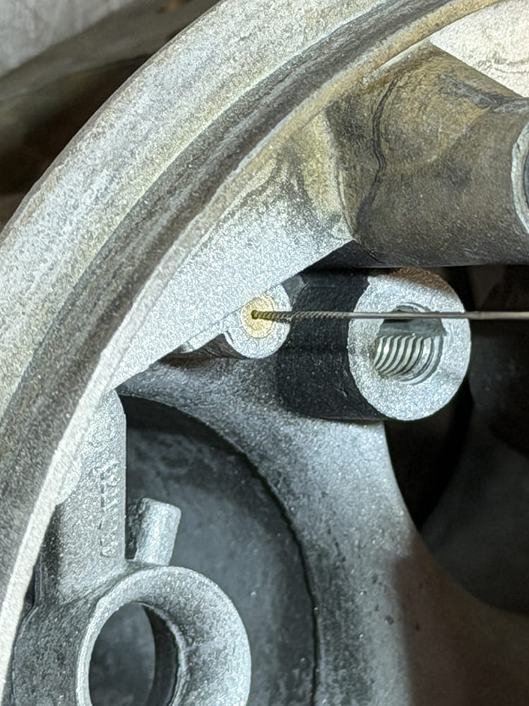
Using a fine wire broach tool to clear debris from an idle air bleed orifice inside the Holley main body.
Compressed air and solvent confirm that every internal air passage is clean and unobstructed, protecting the idle, transition, and main-metering circuits from contamination that can upset calibration.


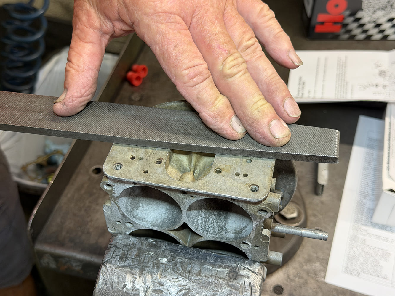
Truing and deburring the gasket sealing surface on the bottom of a Holley 4150 main body using a flat file.
A flat file lightly dresses the main body to throttle body mounting surface, revealing high spots and correcting minor warpage so the new gasket can seal evenly and prevent vacuum leaks.


Top-down view of a cleaned four-barrel Holley 4150 main body clamped into a bench vise for flange resurfacing.
With the mounting surface carefully filed flat and cleaned of debris, the main body is ready to be joined to the throttle body with a new sealing gasket.


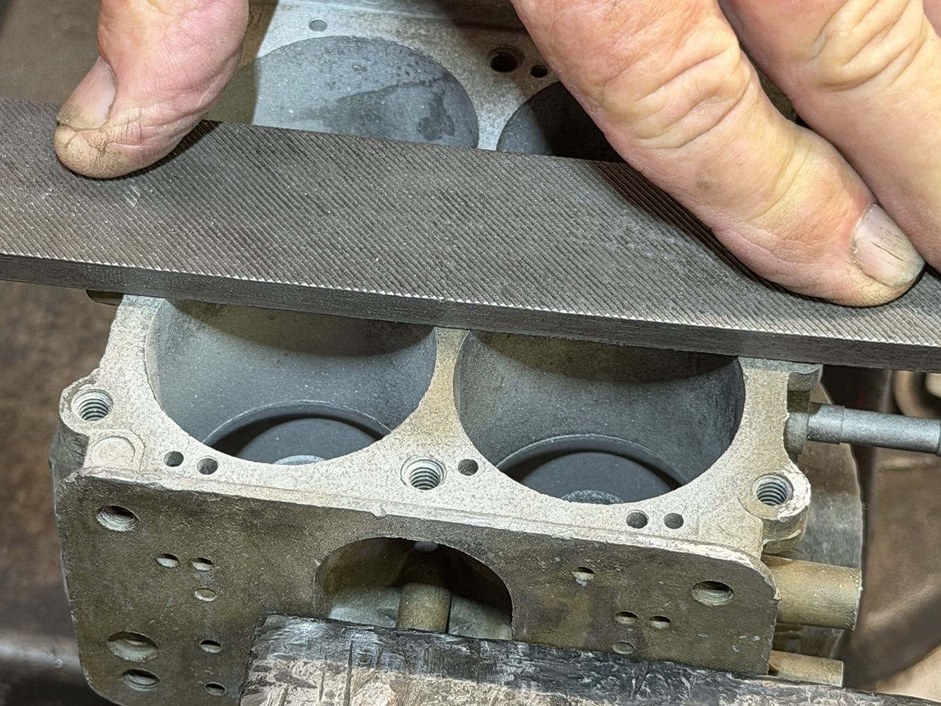
Mechanic hand-filing the metering block mating surface of a Holley carburetor to ensure a leak-free seal.
A flat file checks and trues the main body’s metering block mounting surfaces, removing minor high spots that could compromise gasket sealing and create internal fuel leaks.


Underside close-up of a Holley baseplate showing mounting screw holes and fastener securing it to the main body.
Viewed from below, the throttle body screws align the baseplate with the main body, providing the clamping force needed to maintain a secure, leak-free gasket seal.


Bottom view of the reassembled Holley 4150 throttle plate with all baseplate-to-main-body screws tightened.
With every throttle body screw installed, each fastener is tightened to specification in stages, seating the baseplate evenly without distorting the main body or compromising gasket sealing.


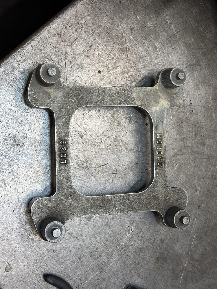
Vintage Moroso 6207 cast aluminum open-plenum carburetor work stand used for four-barrel Holley.
A dedicated carburetor stand supports the assembly without loading the linkage or throttle shafts, keeping the unit stable and accessible during installation of the remaining components.


Mechanic using a flathead screwdriver to tighten the baseplate mounting screws on an inverted Holley 4150 carburetor.
A torque wrench brings the throttle body screws to specification by applying controlled clamping force that secures the baseplate while protecting the carburetor casting and the fresh gasket.


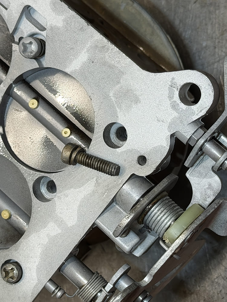
Close-up of screwdriver tightening a countersunk mounting screw on the throttle plate flange of a Holley carburetor.
Tightening the throttle body screws in an alternating pattern distributes clamping pressure evenly, reducing the chance of warping the baseplate or creating a vacuum leak at the gasket.


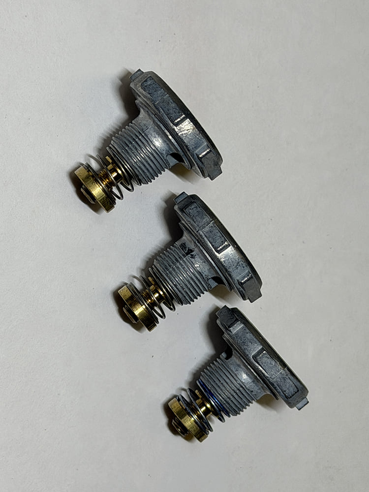
Side profile of three Holley single-stage performance power valves showing threaded bases, return springs, and valve heads.
The replacement power valves are selected to match the carburetor’s calibration, opening under the proper vacuum conditions to enrich the main circuit when engine load increases.


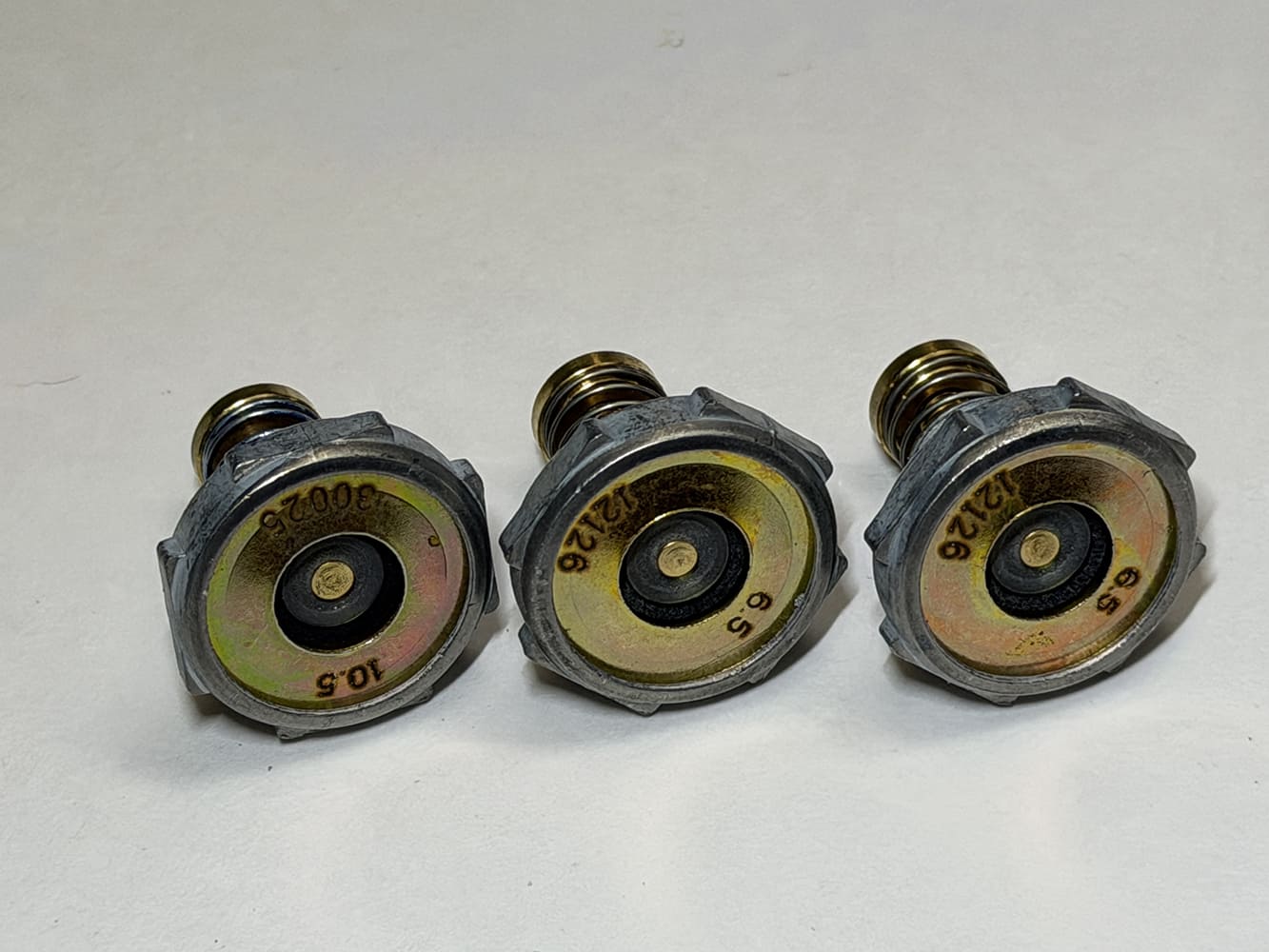
Bottom view of three Holley power valves highlighting the stamped vacuum ratings: 10.5 in-Hg and two 6.5 in-Hg units.
Stamped numbers identify each power valve’s opening point in inches of manifold vacuum, allowing the correct valve to be matched to the engine’s operating requirements.


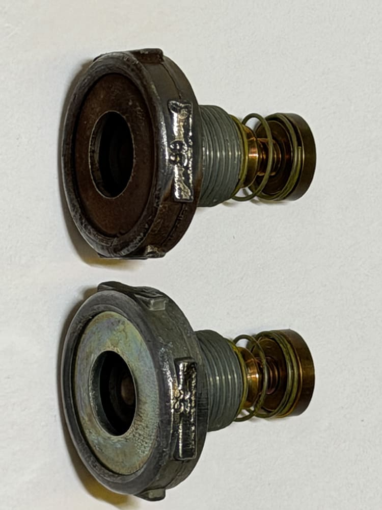
Underside view of two worn Holley carburetor power valves with aged and blown rubber vacuum diaphragms.
From the side, the power valve’s threaded body, sealing surface, and spring-loaded diaphragm are visible, showing how the assembly mounts within the metering block.


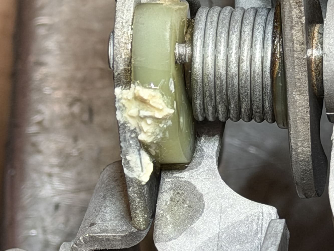
Extreme macro shot of dried grease and corrosion on a nylon throttle cam and return spring on a Holley carburetor linkage.
A light coating of white lithium grease lubricates the accelerator-pump cam and contact surfaces, reducing friction while allowing the linkage to move smoothly through its full travel.


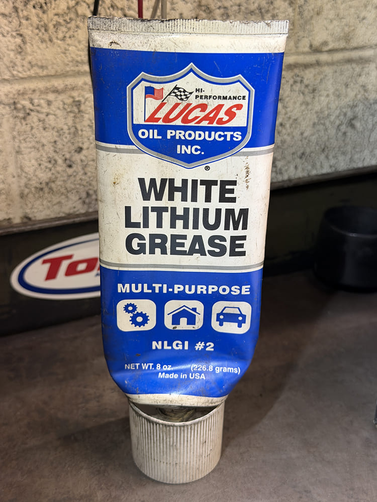
Tube of Lucas multi-purpose NLGI #2 white lithium grease used for lubricating mechanical carburetor linkage components.
White lithium grease provides a durable lubricant for the carburetor linkage, helping prevent dry contact and wear without running off the small moving components during operation.


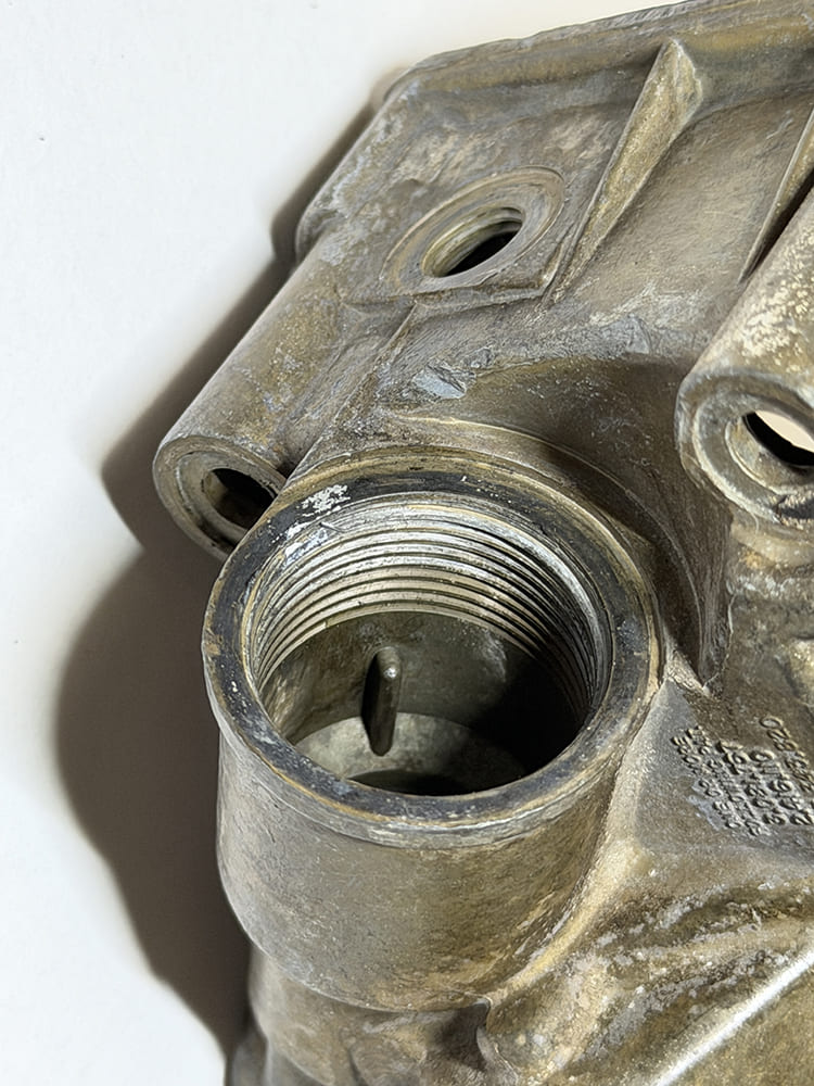
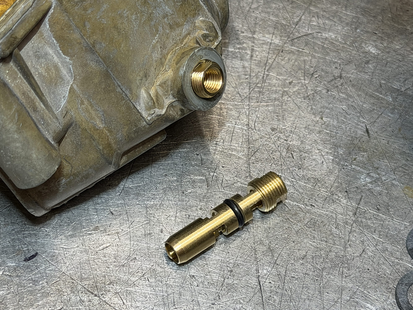
Detailed close-up of the threaded fuel inlet and needle-and-seat orifice inside a cast-zinc Holley carburetor fuel bowl.
The fuel-bowl inlet port accepts the filter and inlet fitting, directing fuel into the bowl while providing a serviceable connection for the carburetor’s supply line.


Close-up of technician placing a round fiber sealing gasket onto the threaded body of a Holley power valve.
A new gasket is placed on the replacement power valve, ensuring a reliable seal between the valvebody and the metering block when the assembly is tightened.


Technician threading a new single-stage power valve into the cavity of a Holley carburetor metering block.
The power valve threads into the metering block, where manifold vacuum controls its opening point and adds enrichment when increased engine load demands additional fuel.


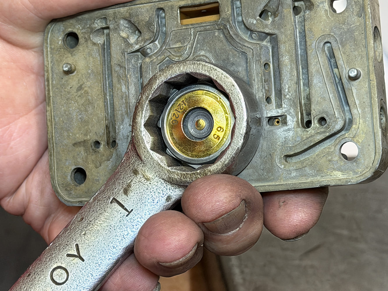
Using a 1-inch box-end wrench to snug and tighten a 6.5-rated power valve into a Holley metering block.
The power valve and both metering block assemblies are tightened carefully, seating their gaskets evenly without overtightening the threaded components or damaging the delicate aluminum castings.


Top-down macro view of a brass power valve assembly properly seated in the fuel well of a Holley metering block.
Fully installed, the power valve sits securely in the metering block, ready to respond to manifold-vacuum changes and supply additional fuel during higher-load engine operation.


Reusable blue non-stick gasket aligned and positioned over the fuel passages and power valve on a Holley metering block.
With the metering block installed against its new gasket, the calibrated fuel circuits are properly positioned between the main body and the adjacent fuel bowl.


Perimeter blue fuel bowl gasket laid out next to the jet and power valve side of a Holley carburetor metering block.
A new bowl gasket is aligned on the metering block, sealing the fuel passages while preparing the assembly for the cleaned and inspected fuel bowl.


Pair of replacement brass adjustable needle and seat assemblies with Viton O-rings for a Holley 4150 carburetor.
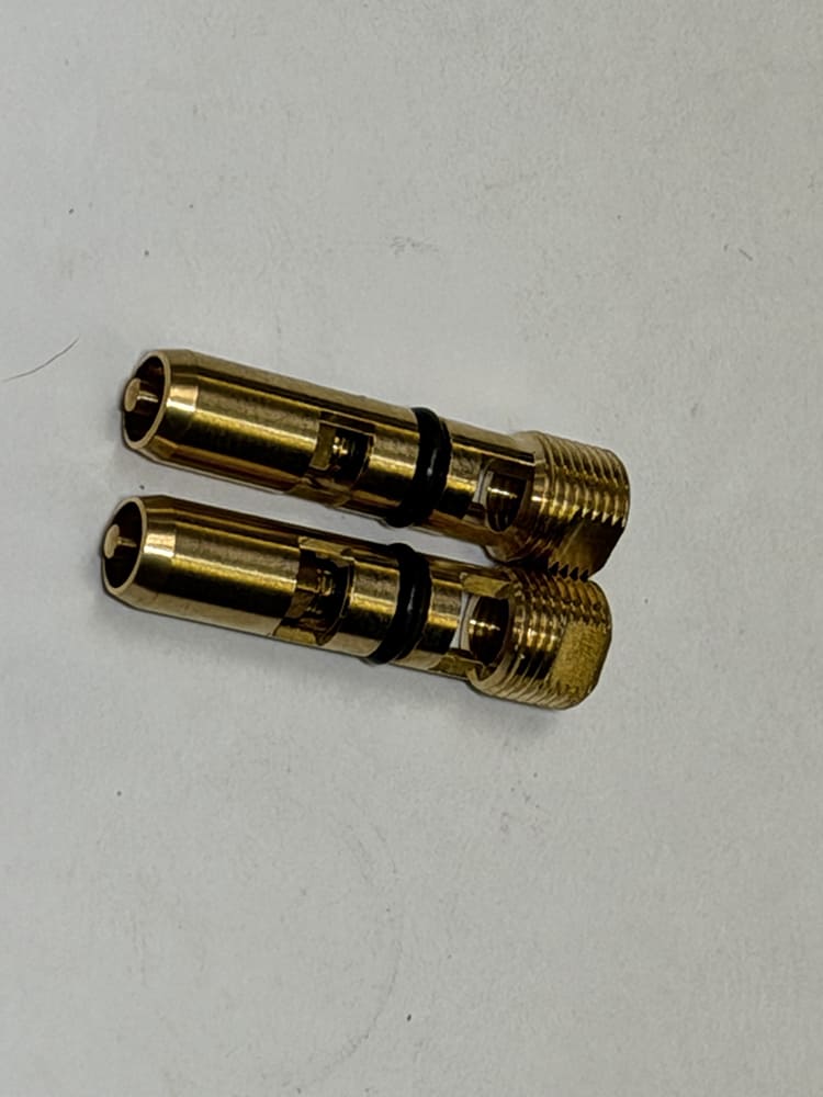
The needle-and-seat assembly regulates fuel entering the bowl, working with the float to maintain the correct fuel level across varying engine speeds and operating demands.


Brass needle and seat assembly positioned next to the top threaded fuel inlet port of a Holley carburetor float bowl.
The needle-and-seat assembly is installed in the fuel bowl, where it works with the float to regulate incoming fuel and maintain the proper operating level.


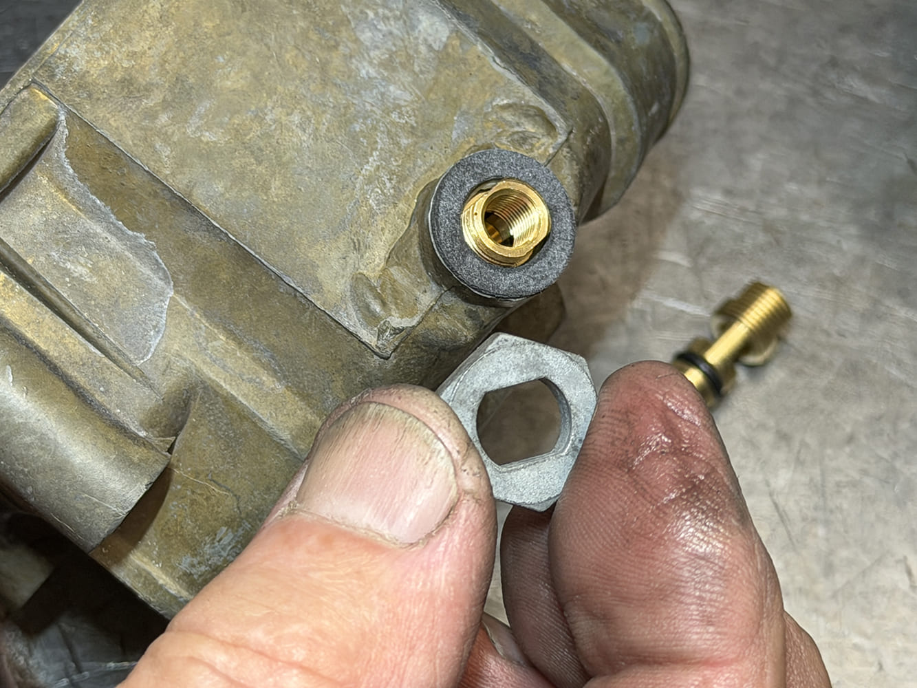
Mechanic fitting a fiber sealing washer and hex lock nut over the threaded needle-and-seat boss on a Holley float bowl.
The adjusting nut threads onto the needle-and-seat assembly, providing the precise vertical movement needed to establish the float setting and control fuel level.


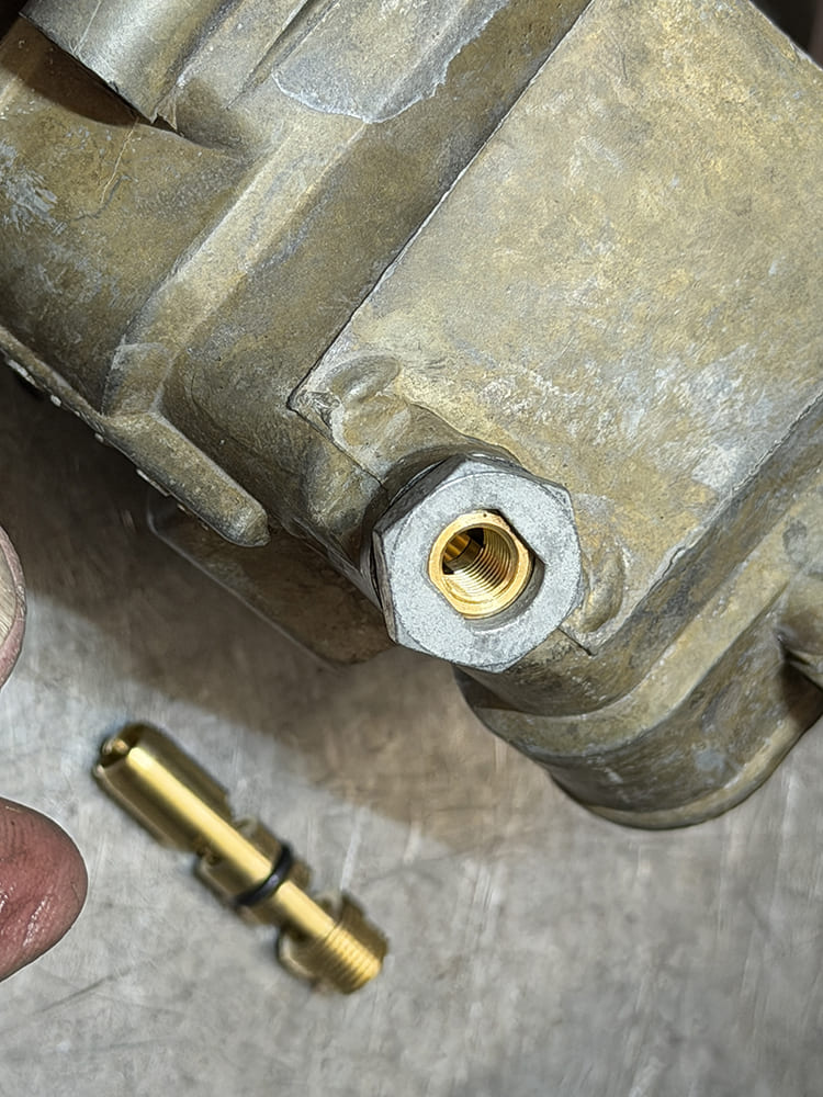
Hex lock nut installed on fuel bowl inlet boss next to a replacement brass Viton needle-and-seat valve.
With the adjusting nut installed, the needle-and-seat assembly can be raised or lowered in small increments to set the correct fuel level in the bowl.


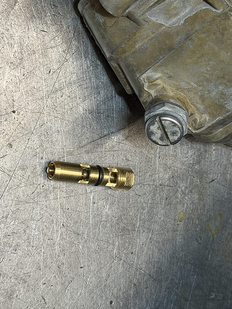
Large slotted adjusting screw threaded into the lock nut on a Holley fuel bowl to set float level height.
The locking screw at the top of the adjusting nut secures the needle-and-seat setting, preventing vibration from altering the established float level during engine operation.
using a screwdriver to remove a fuel bowl sight screw
The sight plug threads into the side of the fuel bowl, providing access to accurately check and set the fuel level while the carburetor is operating.


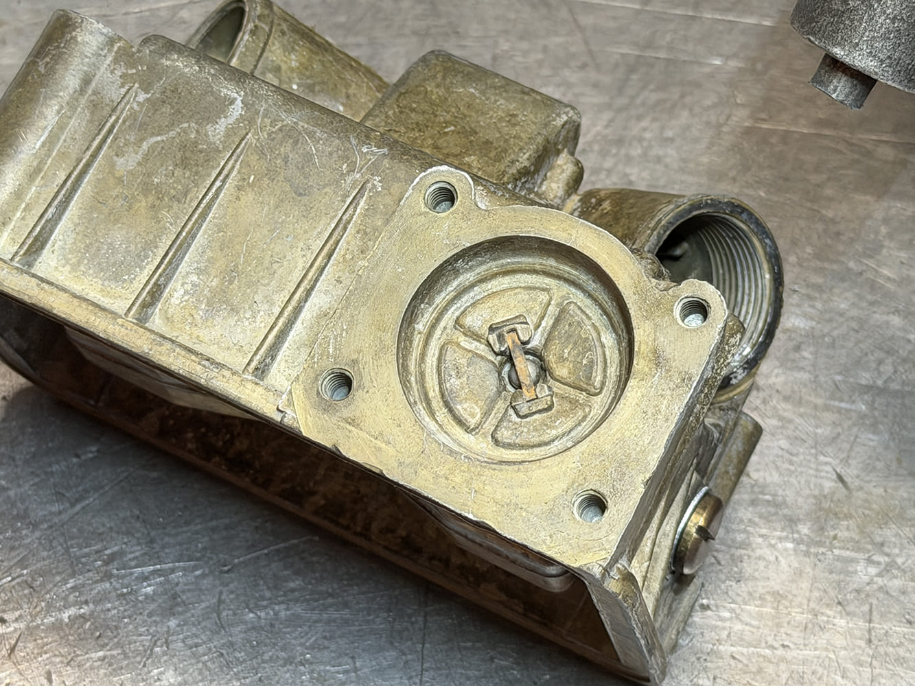
Underside view of a Holley fuel bowl showing the accelerator pump well.
The accelerator-pump cavity at the bottom of the fuel bowl houses the diaphragm and return spring, which produce the additional fuel shot needed during throttle opening.


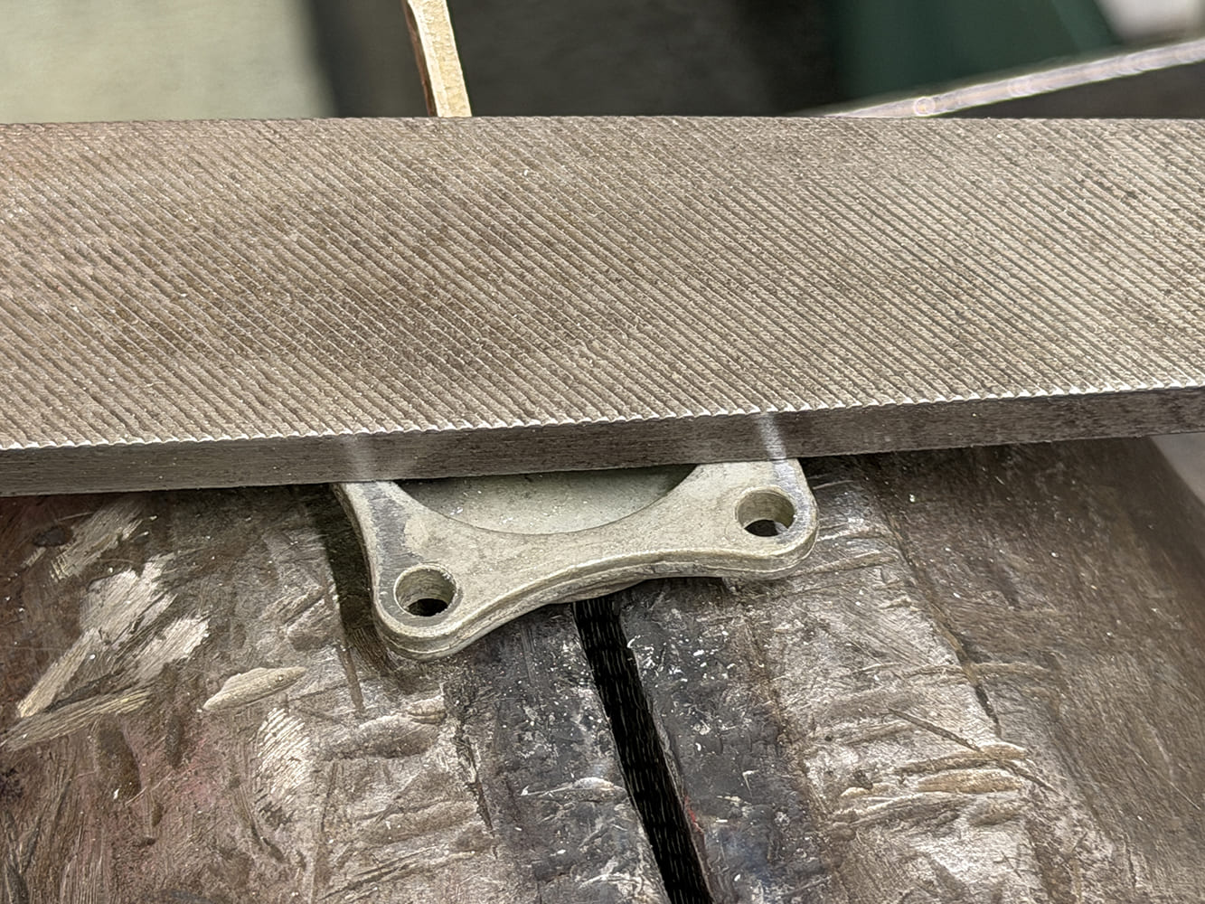
Filing the mounting ears of a Holley accelerator pump cover flat in a bench vise to prevent fuel leaks.
A flat file lightly checks the accelerator-pump cover, revealing raised areas and correcting minor distortion to ensure the diaphragm can seal against a true, flat surface.


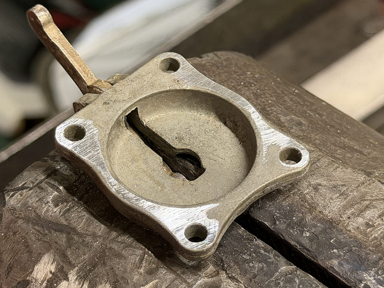
Cleaned Holley accelerator pump housing clamped in a bench vise showing a freshly trued, flat sealing surface.
The accelerator-pump mounting surface is checked for flatness before assembly to help the diaphragm seal evenly and prevent fuel leaks that could weaken pump-shot delivery.


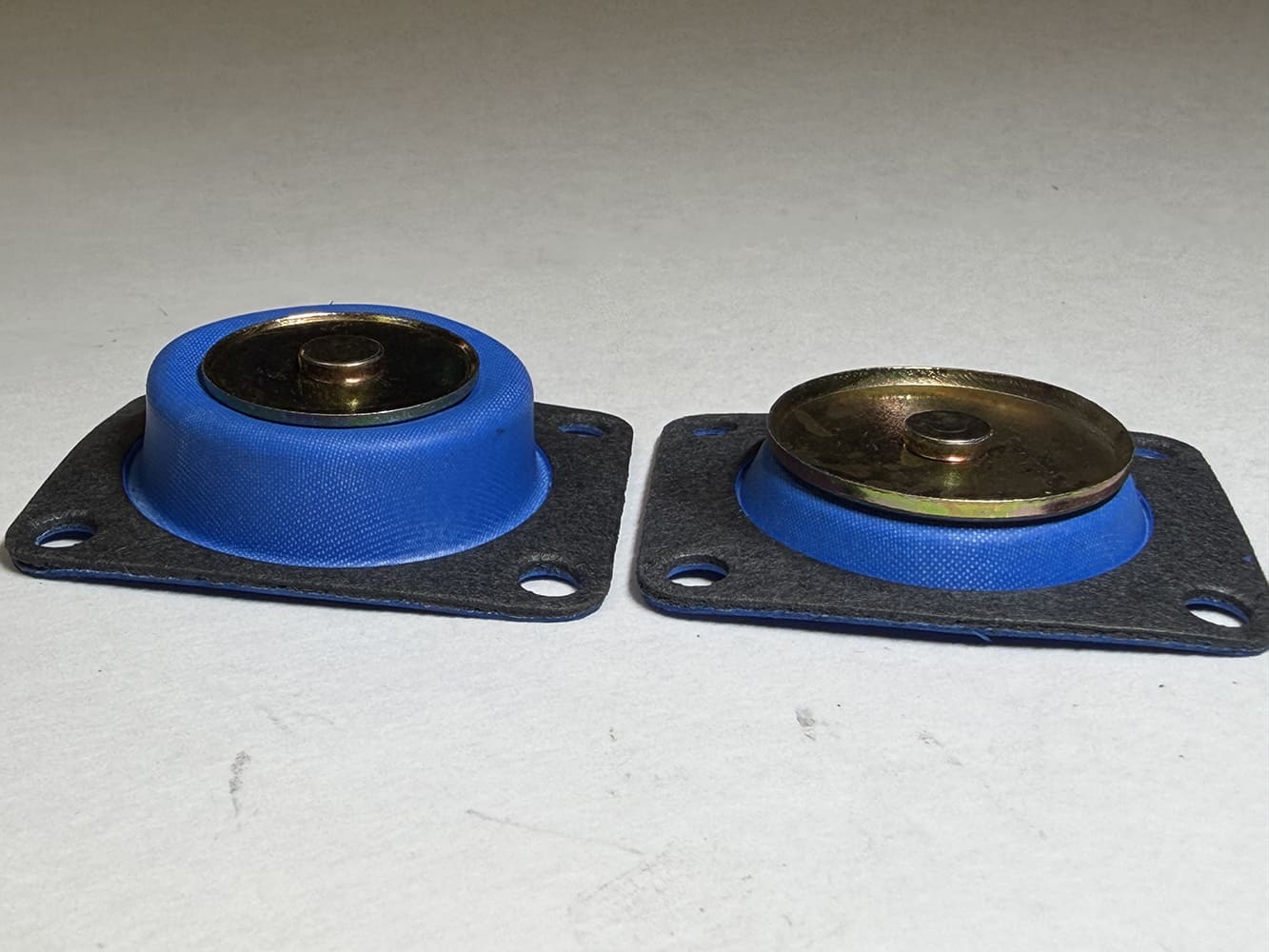
Pair of modern blue alcohol-resistant synthetic rubber accelerator pump diaphragms for a Holley 4150 rebuild.
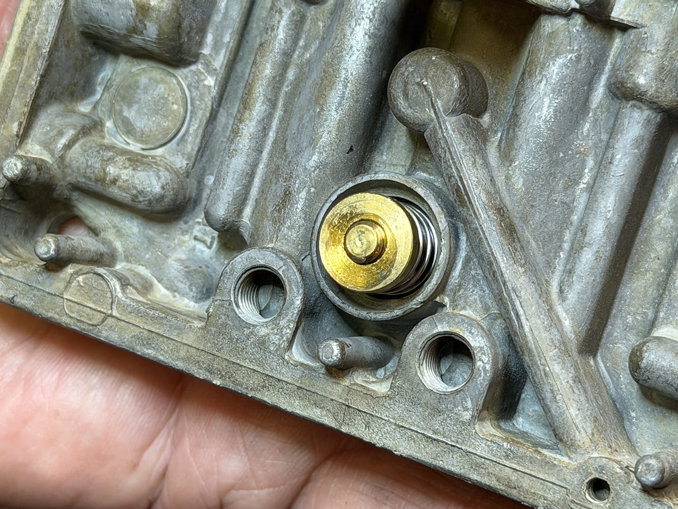
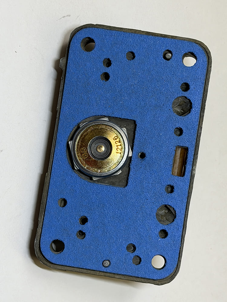
The larger 50cc accelerator-pump diaphragm sits on the left, while the blue 30cc diaphragm on the right uses fuel-compatible material suitable for today’s varied gasoline blends.


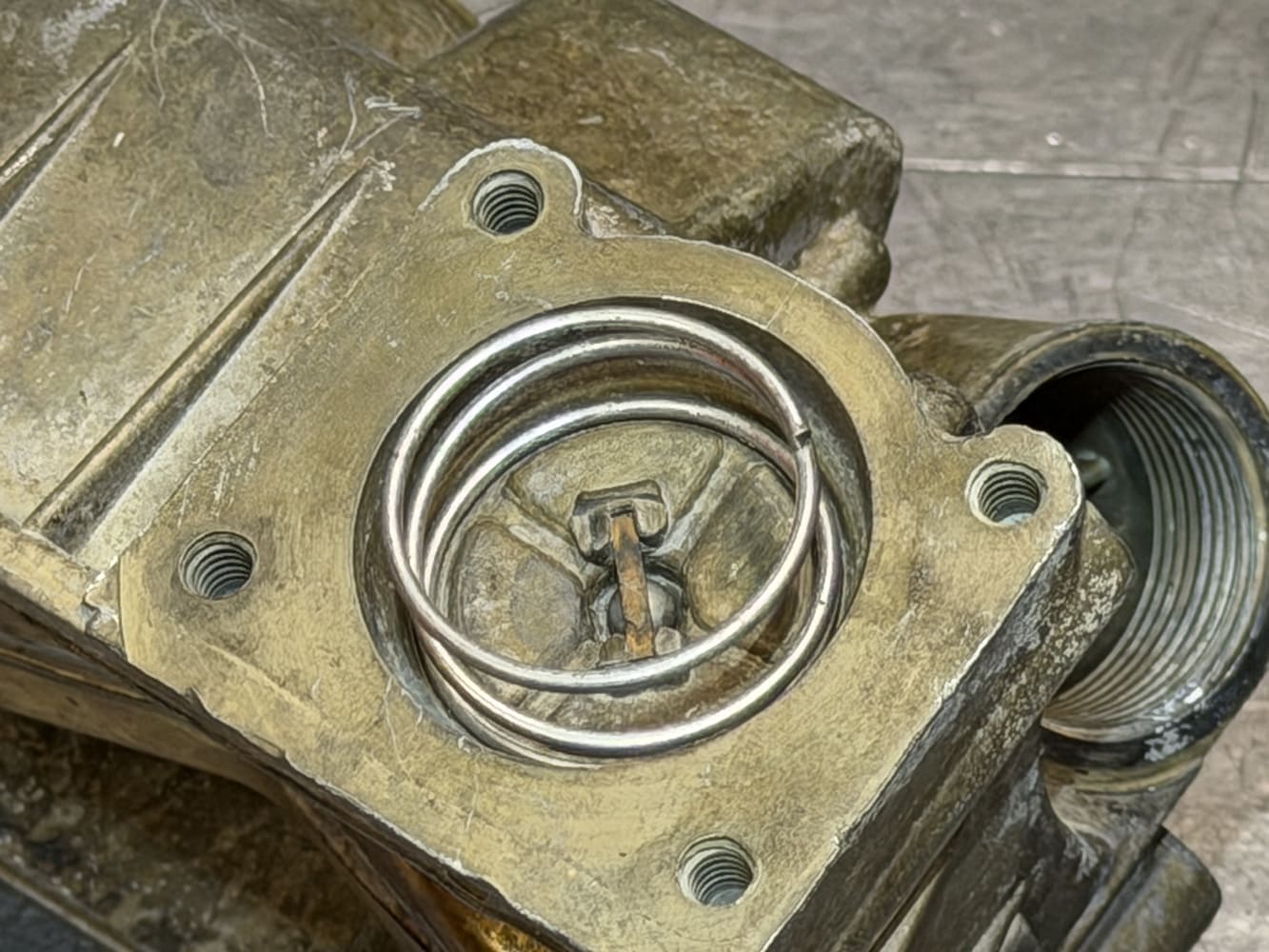
Installing the conical accelerator pump return spring over the check valve inside the Holley fuel bowl pump well.
The accelerator-pump return spring fits inside the cavity with the check ball centered below it, ensuring proper diaphragm return and one-way fuel control between pump strokes.
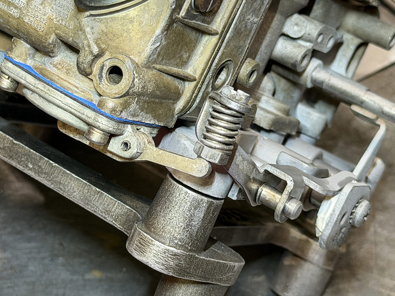
Close-up of the spring-loaded accelerator pump adjustment screw and actuating lever linkage on an assembled Holley carburetor.
The accelerator-pump actuating lever is checked against the pump lever, confirming proper contact and travel so throttle movement produces an immediate, consistent fuel shot.


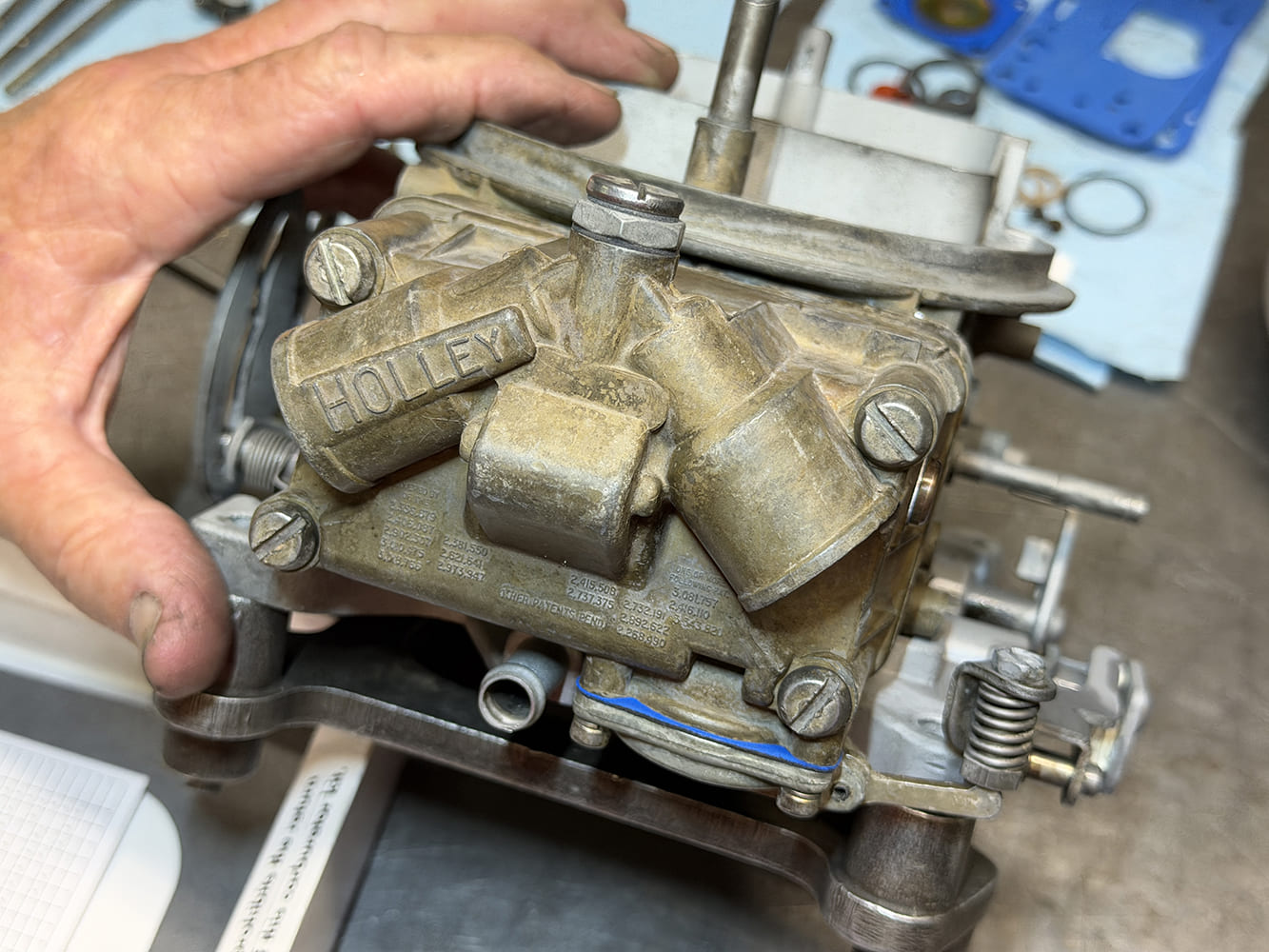
Hands aligning and positioning the secondary float bowl and metering block onto a Holley 4150 carburetor main body.
This end view shows the installed accelerator-pump assembly, including the cover and linkage that convert throttle movement into the fuel shot required during acceleration.


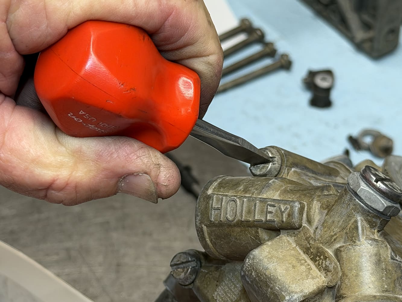
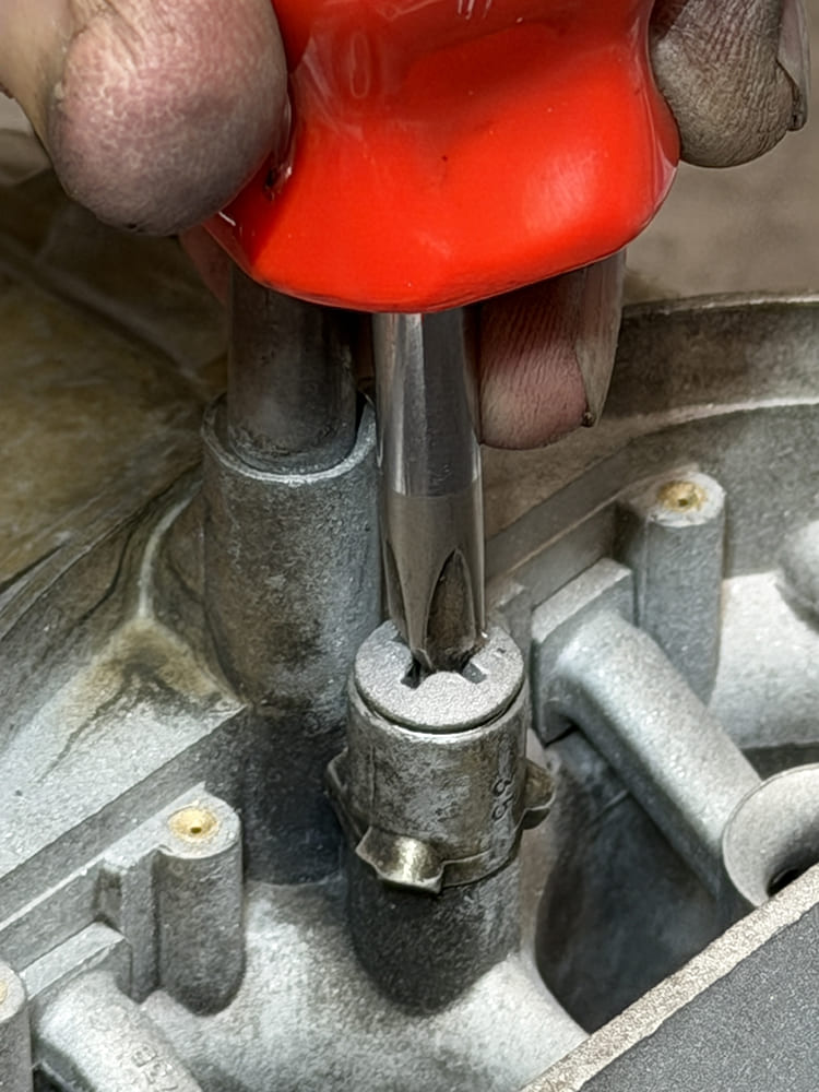
Technician using a stubby flathead screwdriver to tighten the fuel bowl extension bolts into a Holley 4150 main body
The fuel-bowl screw passes through the bowl and metering block, drawing both components evenly against their gaskets to create a secure, leak-free assembly.


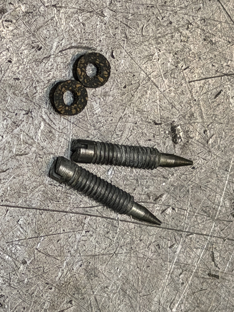
Pair of threaded brass idle mixture needle screws shown alongside replacement cork seal gaskets for a Holley rebuild.
The idle-mixture screw and its sealing gasket meter fuel through the idle circuit, allowing precise adjustment while preventing unwanted air from entering around the threads.


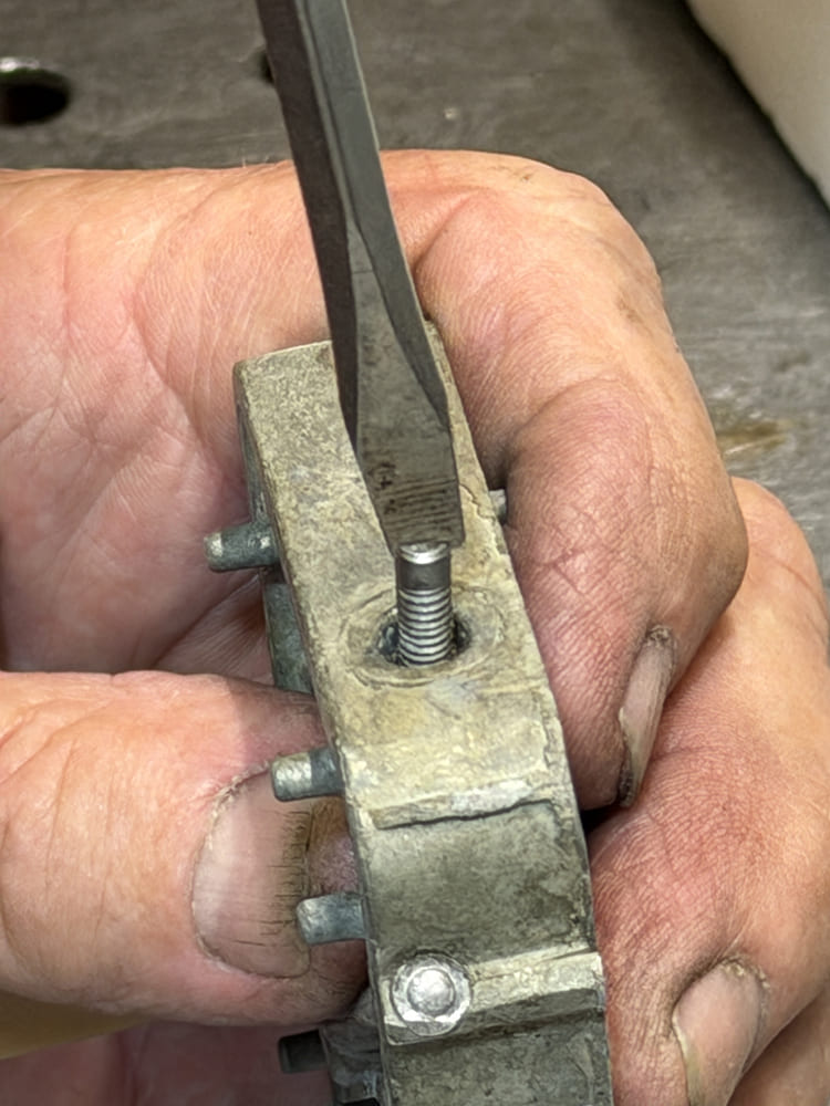
Using a flathead screwdriver to thread and lightly seat an idle mixture adjusting screw into the side of a Holley metering block.
The idle-mixture screw threads into the metering block, where careful adjustment controls idle-circuit fuel delivery and helps establish a smooth, stable idle once the engine is running.


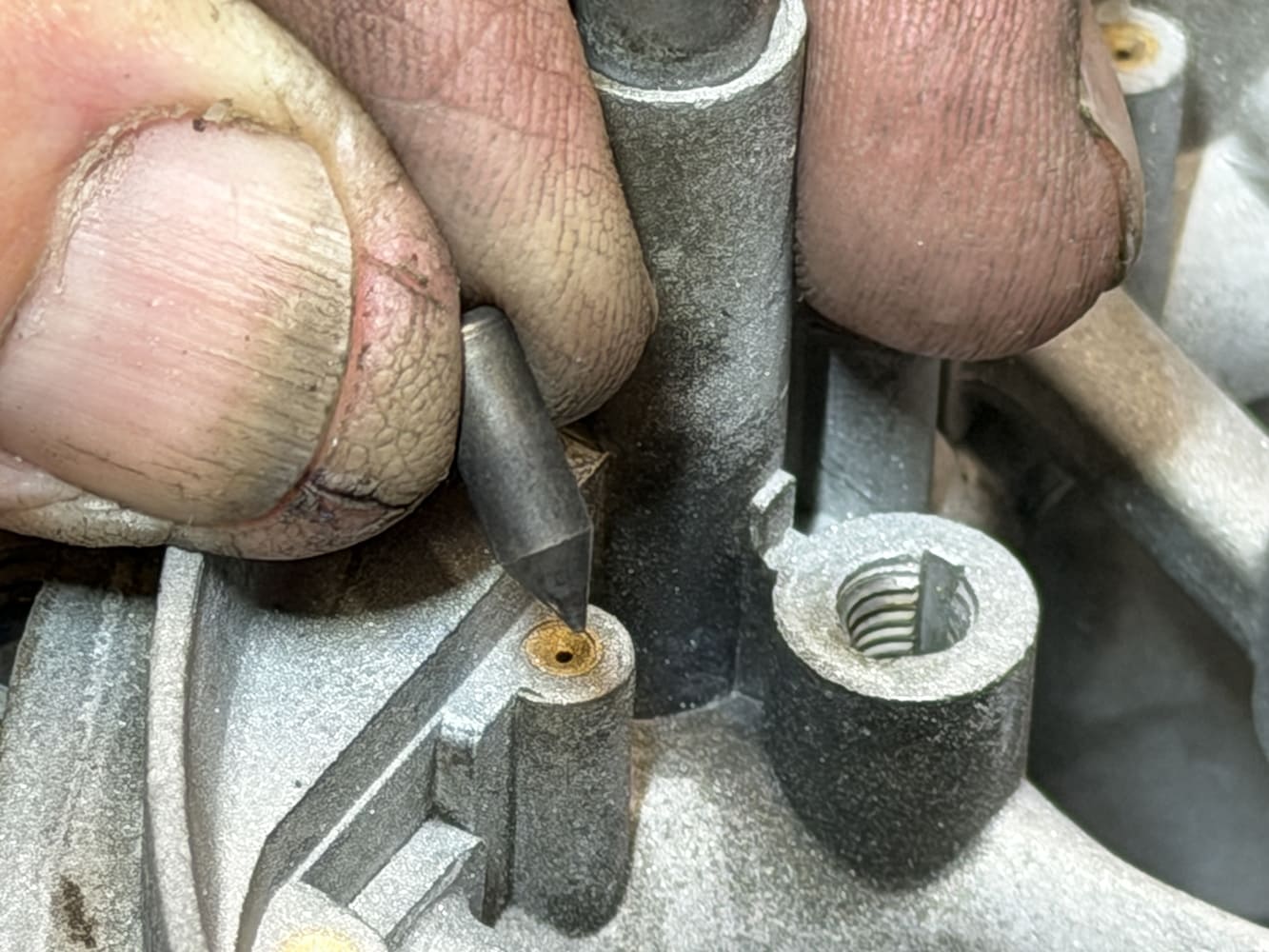
Close-up of technician dropping the pointed steel accelerator pump discharge check valve into the main body well of a Holley carburetor.
The accelerator-pump discharge-nozzle check valve prevents fuel from draining backward, ensuring the pump shot reaches the boosters immediately when the throttle opens.


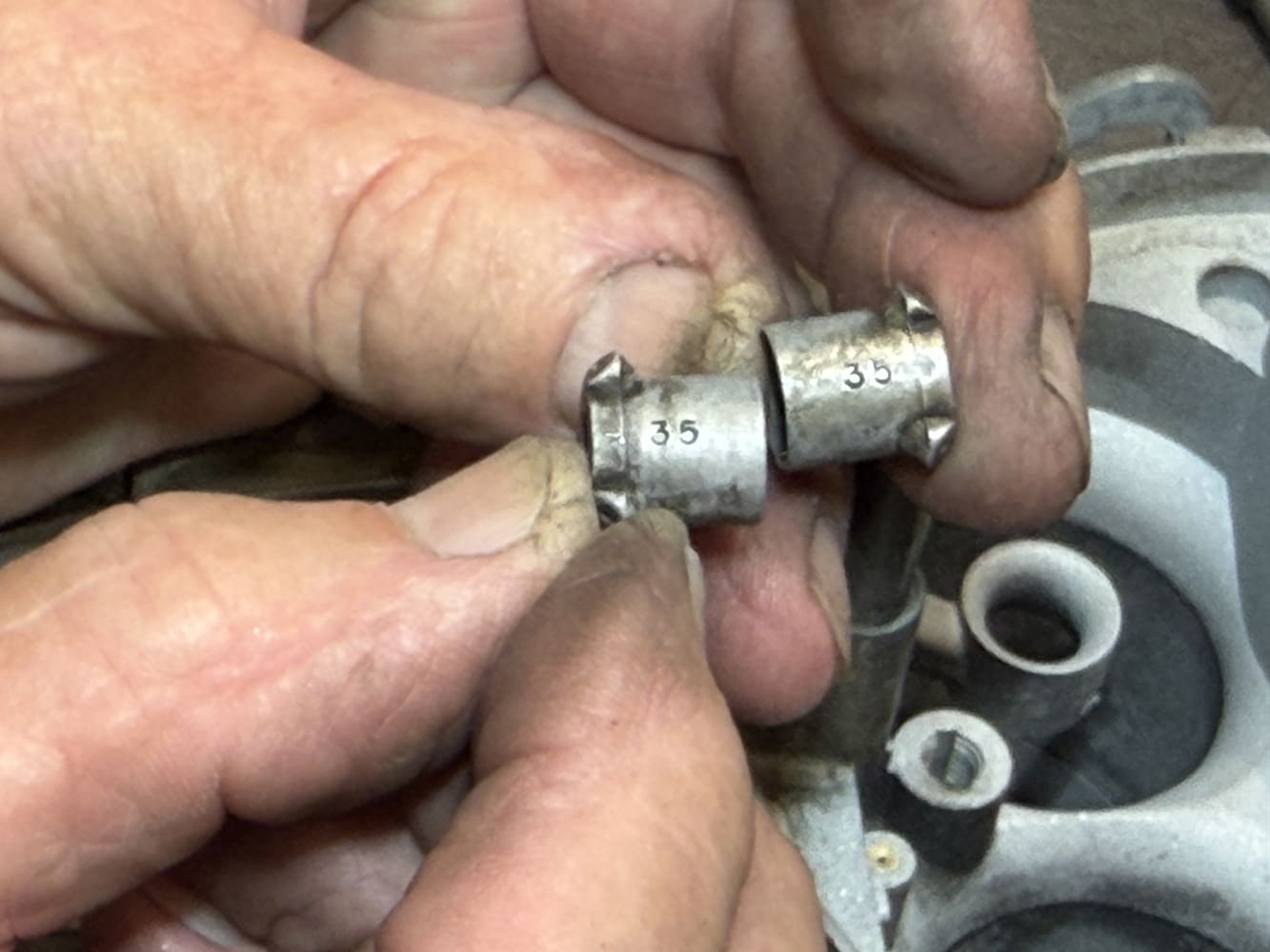
Technician holding two size 35 accelerator pump discharge squirter nozzles showing orifice ports for a Holley carburetor.
Discharge-nozzle numbers indicate orifice size; this L88 uses matching #35 nozzles on the primary and secondary sides to deliver equal accelerator-pump fuel volume.


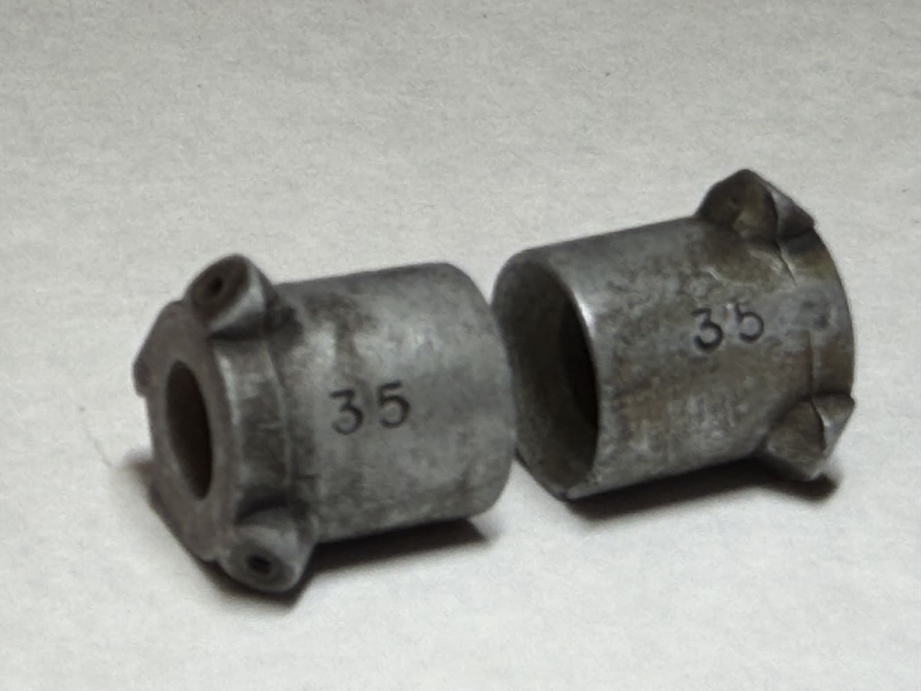
Macro view of a pair of stamped size 35 accelerator pump discharge squirter nozzles for a Holley 4150 carburetor.
A close-up of the accelerator-pump discharge nozzle shows its calibrated outlets, which direct the added fuel shot into the airstream when the throttle opens.


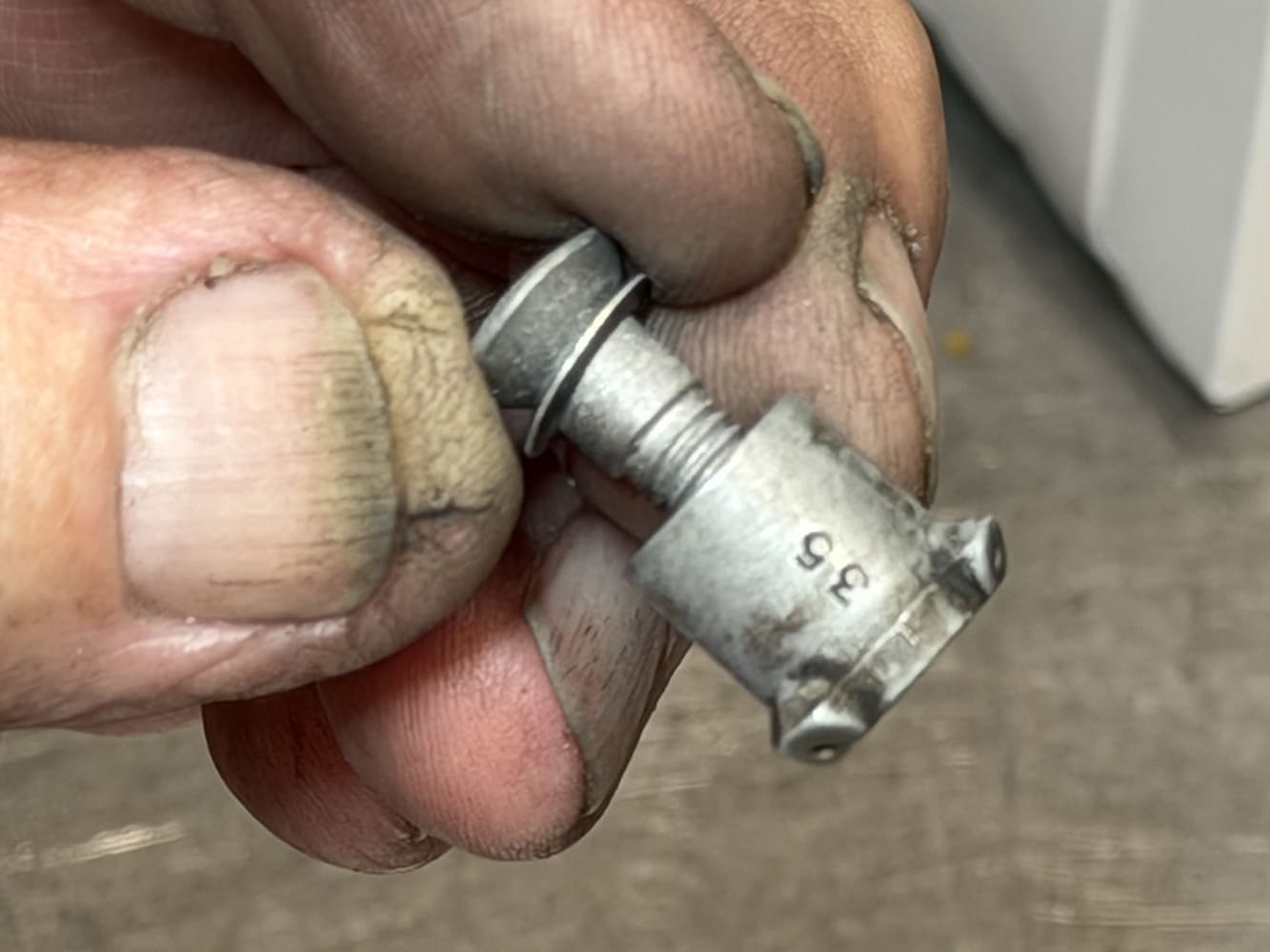
Close-up of technician holding a size 35 accelerator pump discharge nozzle with its hollow retaining screw and gasket.
The mounting screw passes through the accelerator-pump discharge nozzle, securing it to the main body while maintaining proper alignment of its fuel passage.


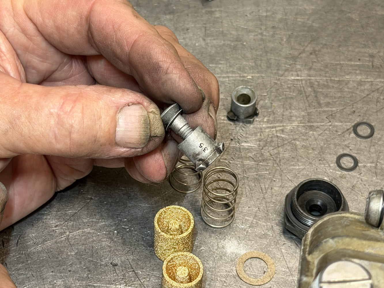
Accelerator pump nozzle held over new sintered bronze fuel inlet filters, return springs, and fiber gaskets on a workbench.
The discharge-nozzle fuel inlet receives its filter, spring, and fitting, keeping debris from the calibrated passage while maintaining positive fuel delivery during pump operation.


Top-down view of the size 35 pump squirter nozzle installed inside the choke horn of a Holley 4150 main body.
The primary accelerator-pump discharge nozzle is seated in the main body, aligning its calibrated outlets to deliver the pump shot directly into the primary bores.


Using a stubby Phillips screwdriver to tighten the accelerator pump discharge nozzle retaining screw inside the carburetor air horn.
The discharge-nozzle screw is tightened carefully, securing the nozzle and its gasket without distorting the small casting or restricting the calibrated fuel outlet passages.


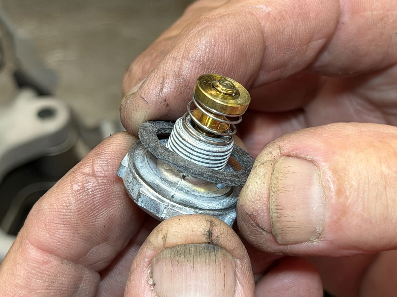
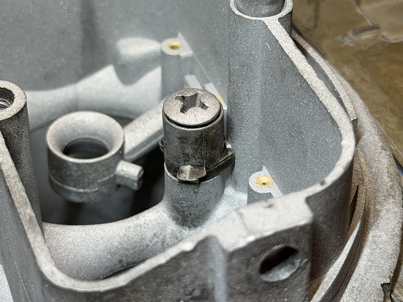
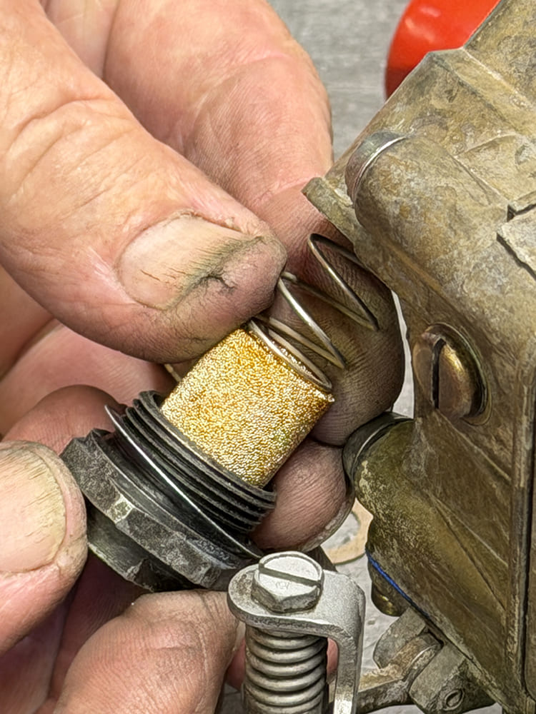
Technician inserting a bronze stone fuel filter and conical spring into the inlet fitting of a Holley carburetor float bowl.
The fuel-inlet filter slides into the bowl fitting, trapping debris before it reaches the needle-and-seat assembly, the float chamber, or the carburetor’s calibrated fuel circuits.


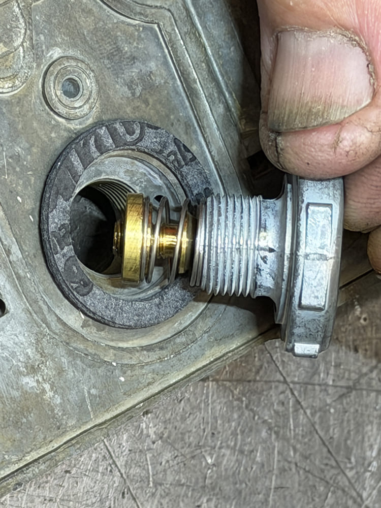
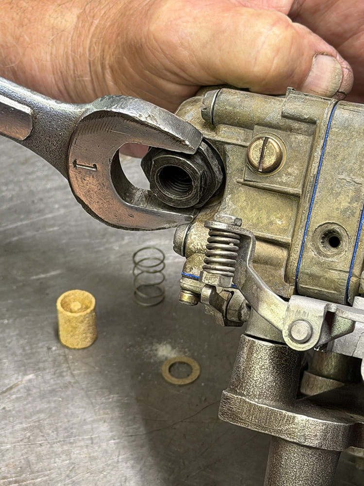
Tightening the fuel inlet nut and sealing washer onto a Holley fuel bowl using a 1-inch open-end wrench.
The fuel-inlet fitting is tightened against its sealing surface, securing the filter and creating a secure, leak-free connection for the carburetor’s incoming fuel supply.


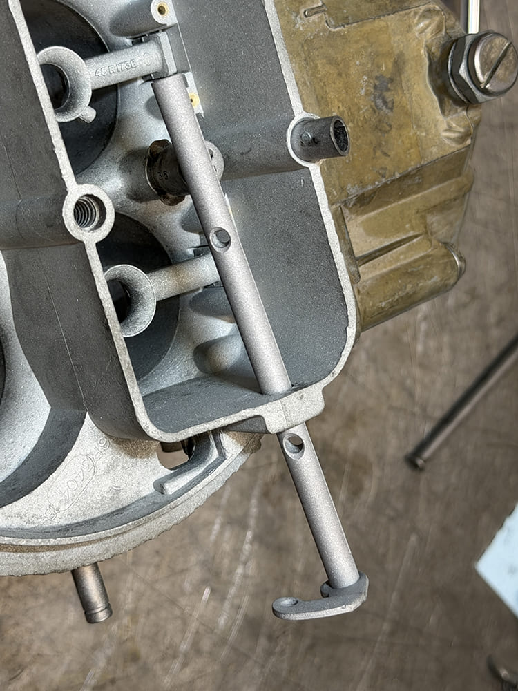
Overhead view of the choke butterfly shaft inserted through the air horn casting on a Holley 4150 carburetor main body.
The choke-blade shaft slides through the main body, providing the pivot that supports the blade and enables controlled airflow during cold-engine startup and warm-up.


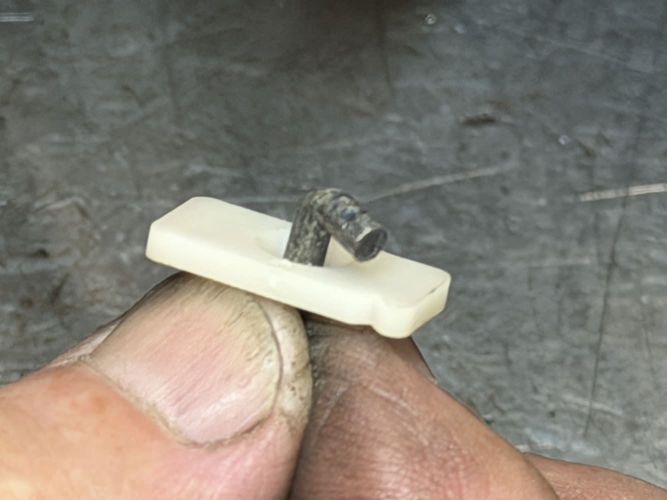
Close-up of the nylon sealing grommet and bent metal choke linkage rod for a Holley 4150 carburetor.
The choke-blade actuating rod and dust cover are installed together, linking the mechanism while shielding the moving joint from contamination that could hinder operation.


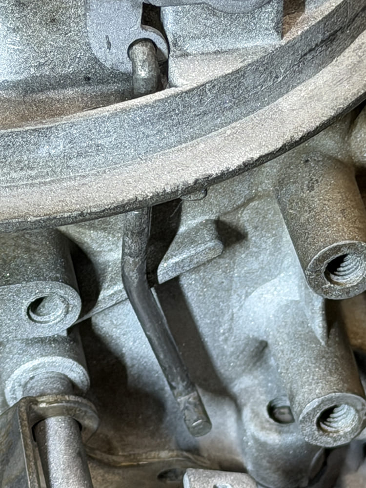
Macro view of the choke operating rod routed along the side of the Holley 4150 main body casting.
With the choke-blade rod installed, movement from the choke mechanism is transmitted directly to the shaft, opening and closing the blade smoothly throughout its full travel.


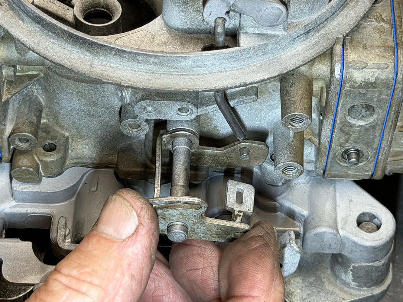
Technician hand-assembling the secondary throttle shaft link and choke cam mechanism on the side of a Holley carburetor.
The fast-idle rod is installed between the choke linkage and the throttle mechanism, allowing the system to increase engine speed during cold starts and initial warm-up.


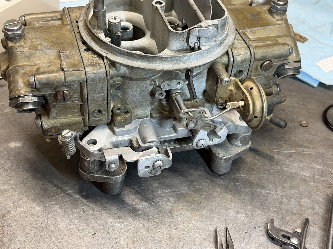
Side view of a rebuilt Holley 4150 850 CFM carburetor highlighting the external choke operating linkage and vacuum pull-off assembly.
Fully assembled, the restored L88 Holley shows its fuel bowls, metering blocks, linkage, and inlet fittings in place, ready for final adjustments, testing, and installation.


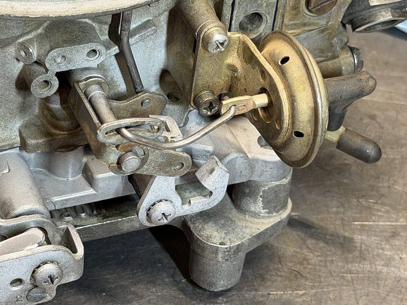
Macro view of the gold dichromate choke vacuum pull-off pod and connecting linkage rod mounted on a Holley 4150 carburetor.
The choke pull-off is installed and connected, leaving the fast-idle cam as the final piece needed to complete and properly operate the carburetor’s cold-start linkage. (We have an original fast-idle cam on its way to complete this project.)


ITGM Source Box Heading

JEGS Web Sources

Holley Web Source

HRBD Web Source

Related Articles

Search Our Site