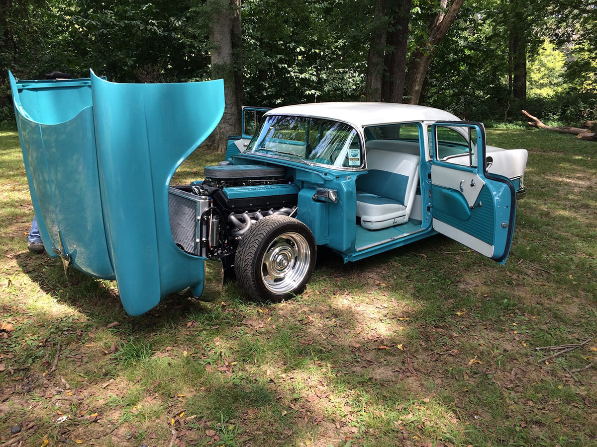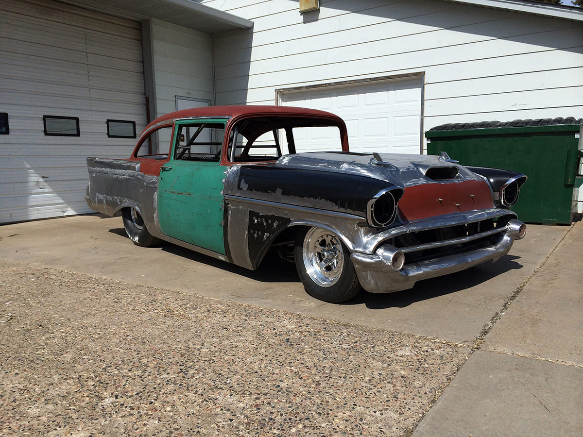

Building a W24-Powered 1957 Chevy Pro Street
Text By Jeff Smith – Photos by Gary Kollofski, Dale Pelvit, and the Author
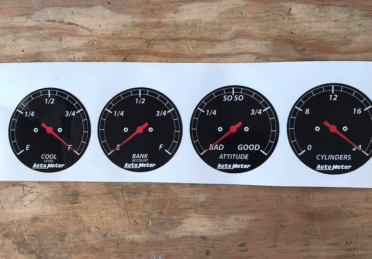
Have you ever played the cylinders game with your car buddies? It counts and includes all functioning cylinders residing in your garage. One word of caution. Don’t play this game with Gary Kollofski if his 1957 Chevy is in the vicinity.
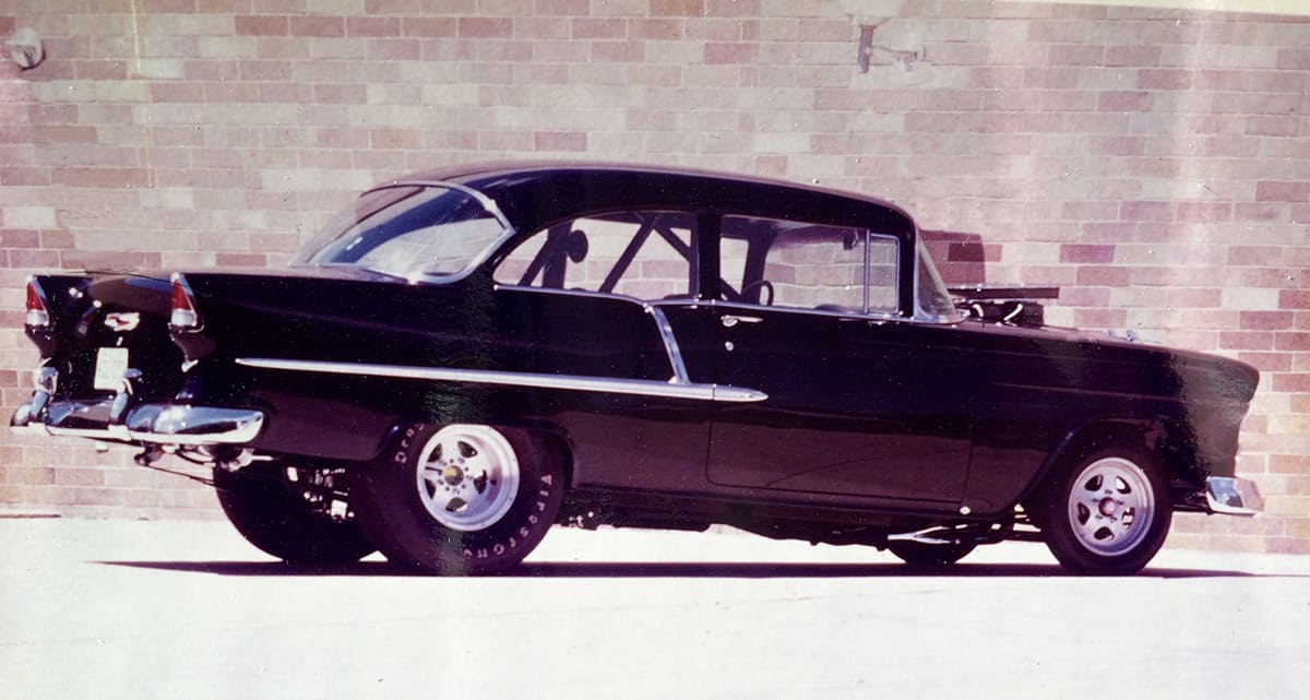
Kollofski is a fan of big cubic inches. But his predilections do not fall within the normal confines of stroker big-block Chevys or even tall-deck monsters that Pro Mod and tractor pullers have made famous. Kollofski has always followed a different alchemist’s path. If his name sounds familiar and you were reading car magazines in 1977 you might remember his bad-to-the-bone black 1955 Chevy that graced the pages of Hot Rod magazine. Many consider that car as among the progenitors of the Pro Street movement. Others remain simply awed by its sinister appearance that, had it survived, would still draw crowds today.

So, after building another 1955 Chevy a few years ago using an obscure Italian marine V-12, Kollofski and coconspirator/fabricator Dale Pelvit tumbled upon a plan that fully intended to raise the high-water mark for outrageousness. The dictionary positions that word as somewhere between startlingly bad and very unusual. Kollofski and Pelvit call it the W24.
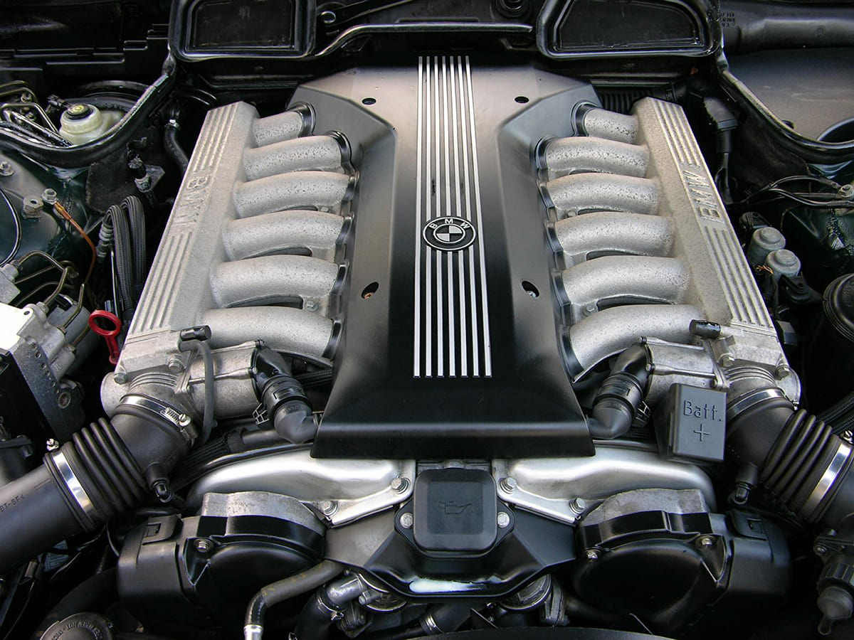
Kollofski had grown to appreciate the BMW sedans from the mid ’90s that were powered by an interesting Bavarian experiment that mated a pair of single overhead cam inline-six cylinders into a V-12. BMW called this engine an M73. Typical of European engine design, it sported 12 cylinders, but they’re all very small. Displacing barely 5.4 liters (328 ci), BMW focused on building an ultrasmooth engine. A V-8 times its firing impulses exactly 90 degrees apart. Americans tend to think a V-twin Harley paint shaker is cool, so a typical 21st century V-8 might seem to Americans as unencumbered with vibration. But to the Europeans it takes a 12-cylinder engine with combustion pulses a mere 60 degrees apart to elevate the application of the word “smooth.” One enduring image is a BMW video revealing a coin vertically balanced on the intake manifold of its running V-12.
BMW rated these engines at 322 hp and 361 lb-ft of torque. Combining them means Kollofski’s W24 should make somewhere near 600 hp and 700 lb-ft of torque from a combined displacement of 656 ci. But power might be a secondary issue–it’s the visual assault that takes precedence. Think of this as a more elegant version of an R2800 Pratt & Whitney Double Wasp radial aircraft engine stuffed into the engine bay of a 1957 Chevy.
Kollofski was just completing his aforementioned turquoise 1955 Chevy with a large displacement marine V-12. While he knew it would draw plenty of media attention, he was already contemplating an even bolder statement—something even more outrageous. The net result was that if one V-12 was good then two had to be better, right? So why not join a pair of V-12s at the hip and create a W24.

The pinnacle of fashion horror for any woman is to arrive at an important social engagement bedecked in a fabulous gown only to meet another flaunting the exact same garment. For car builders, it is to witness others flaunting a similar body mod/paint scheme/engine combination.
Kollofski is in no danger of ever experiencing that emotion.
The plan was hatched one afternoon in the middle of Pelvit’s Minnesota lair and was quickly enabled by a pair of M73 BMW engines. That was also the point where the last easy efforts were achieved. From then on, it only became more of a challenge. The plan proved to be like summiting a steep hill only to discover another even larger mountain directly in your path.
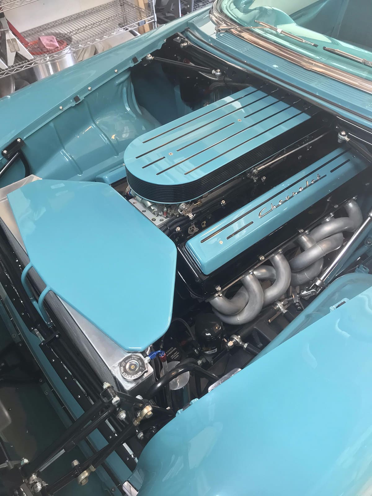
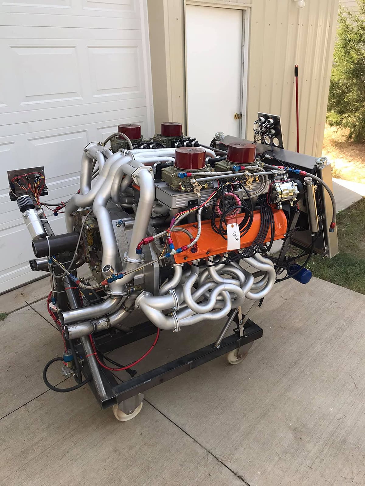
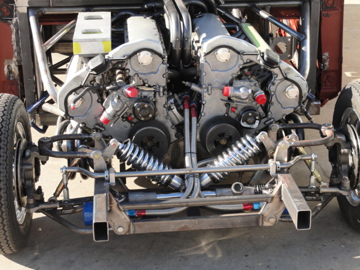
Their first decision was to co-join the engines using a 30-degree angle between them that would place the inboard cylinder banks vertical. This demanded sufficient room down the centerline to allow the inboard exhaust primary tubes–all 12 of them–a place to exit. Pelvit’s plan called for them to comingle toward the rear where they would join with the remaining 12 pipes from the outboard cylinders. A 1-inch-thick aluminum plate connected the blocks together at the rear along with a substantial steel mount in between that ties both blocks together. The challenge through the early stages of the plan was to orient these 24 cylinders in a way that would nestle the entire package within the front fenders of a 1957 Chevy. Once the idea passed the “I think this can work” phase, the real effort began.
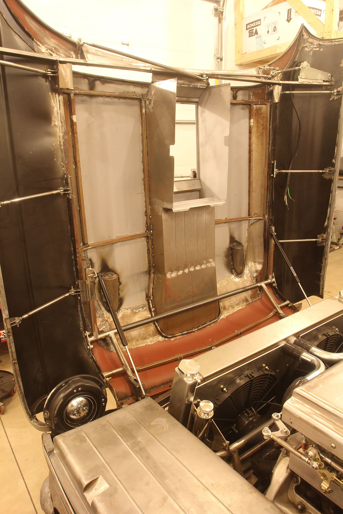
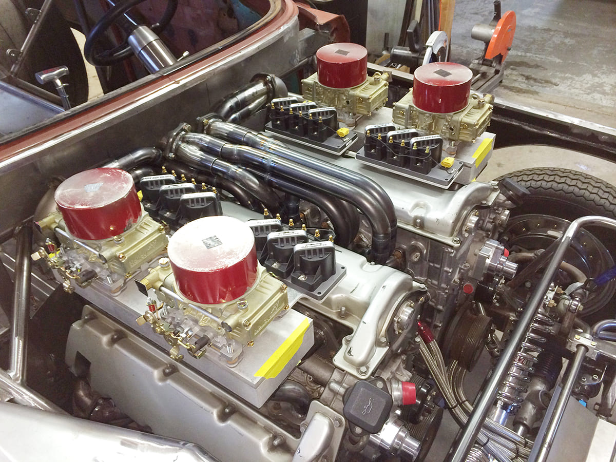
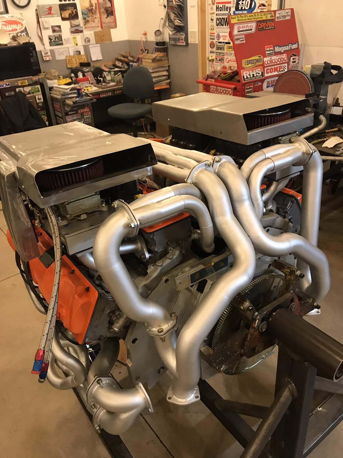
Pelvit constructed a rectangular tube chassis for the 1957 Chevy that cradled the engine. That’s a story that deserves much more attention than we can deliver here as it involves inboard rocker arm shock mounts up front and much, much more. The plan also shelved the original BMW electronic fuel injection in favor (of course) of four small Holley four-barrel carburetors. Since the M73 BMW engine does not use a distributor, a new ignition system was right at the top of the priority list.
At first, the plan was to create a dedicated 24-cylinder firing order (imagine trying to commit that sequence to memory). This would then have compressed the crankshaft movement between cylinder firings down to a scant 30 degrees. That idea created more problems than it solved since the space between teeth on the crank sensor would have been minimal. This called for running each engine with separate Electromotive ignition boxes so the engines operate independently.
But all that paled to insignificance compared to the challenge of designing and executing how to funnel two spinning V-12 crankshafts into one output shaft. Side-by-side engines in the past have been paired most simply by meshing the teeth of both flywheels but this requires one engine to spin backward–a plan that was quickly shelved as far too complex.
The solution involved Bob Bendtsen and Bendtsen Transmission/Speed Gems in Waunakee, Wisconsin, who built a 1-inch-thick aluminum plate that ties both engines together at the rear. The next step was when Kollofski approached Carl Wepplo who owns Atlas Tractor Pulling in nearby Ham Lake, Minnesota. Wepplo’s experience is in wrangling multi-engine tractor pullers into a single-output shaft. His design for the W24 was both simple and elegant.
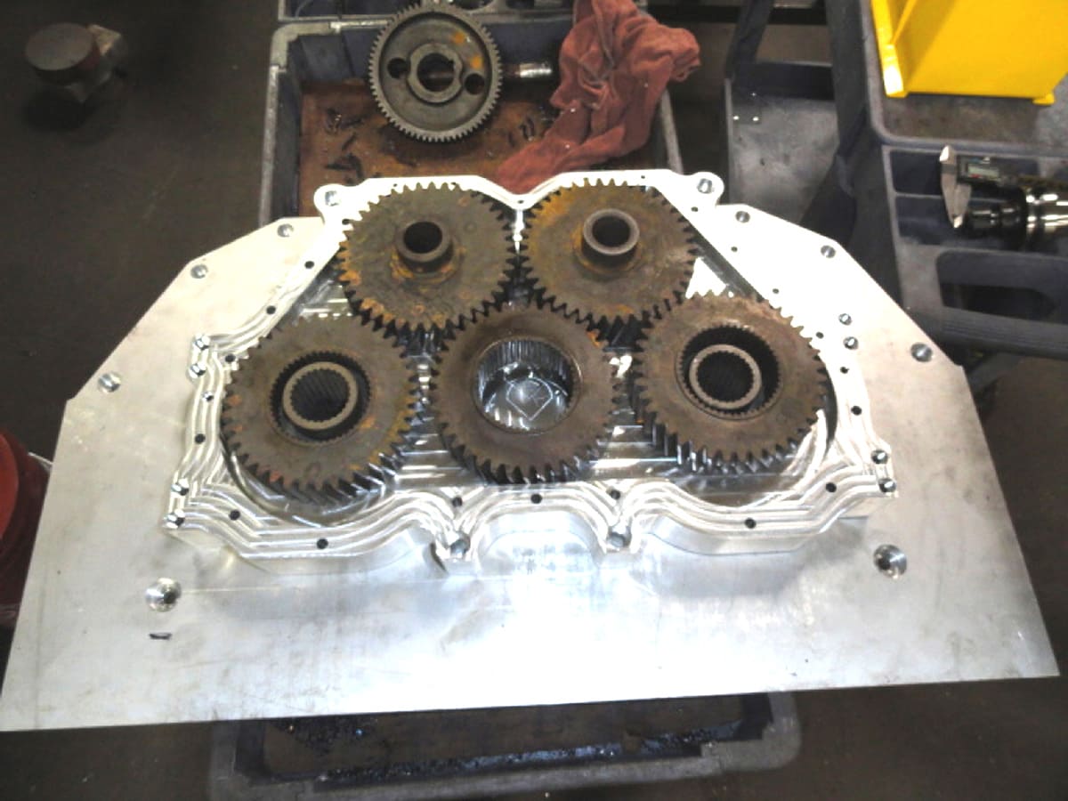
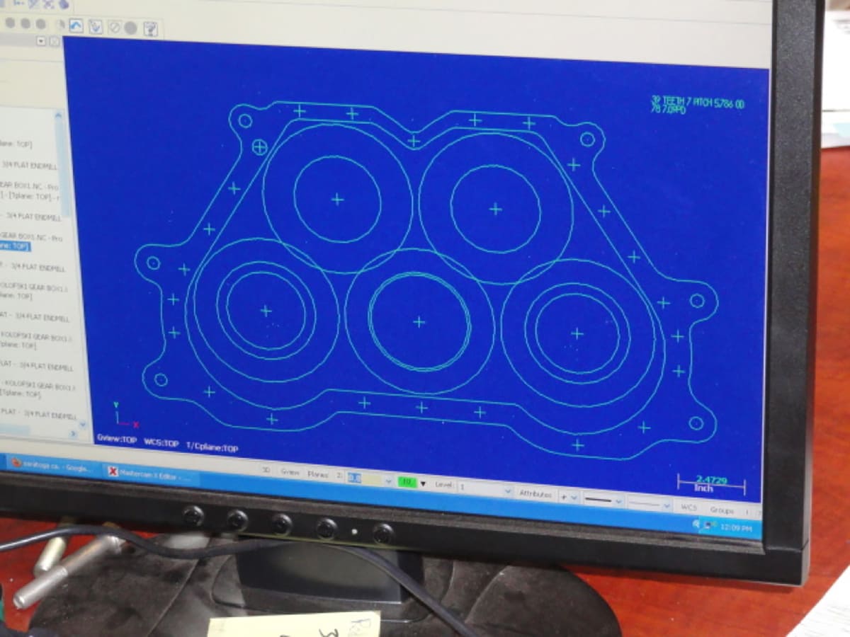
Wepplo used a collection of five hardened steel alloy gears laid out as shown in the accompanying photo. The two lower outboard gears are splined to their respective crankshafts. These gears are in constant mesh with two upper outboard gears as idlers. Those gears are meshed to the lower, center gear that becomes the output splined as an output to a flexplate that connects to a 700-R4 automatic. There is no ratio multiplication so the net effect is transmitting power from both engines in a 1:1 ratio. This assembled gearset was then encased in an aluminum enclosure with its own gear lube that uses a standard Chevy bellhousing pattern so the transmission bolts directly to the cases. Kollofski does not intend to race the 1957 nor lean on it hard but does like the idea of an overdrive transmission, which is how he ended up with the 700-R4.
During our discussion of building this amazing attempt of stuffing 24 cylinders underneath the hood spears of a 1957 Chevy, we asked Kollofski (knowing full well the answer in advance) whether he and Pelvit had created a blueprint or actual plan before diving into this automotive fabrication equivalent of the D-Day landings. Kollofski just laughed and said no, they merely stuffed the engines into the chassis and then Pelvit merely addressed each impediment as it came along. “Sometimes it just amazes me that everything fit and that the engine runs,” Kollofski says. “It really is an amazing feat of engineering.”
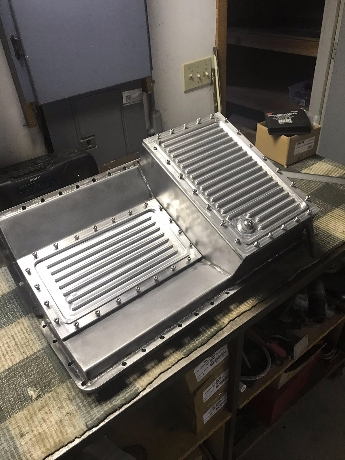
But we are getting ahead of the story. Once the engines were co-joined, it became apparent that the original oil pans would be unsuited to being canted at a fixed 30 degrees. So Pelvit built a large, common steel oil pan with a removable aluminum sump that allows access to the original inboard factory oil pan rail fasteners. The entire oil system is designed around a 9-quart capacity with externally mounted oil filters.
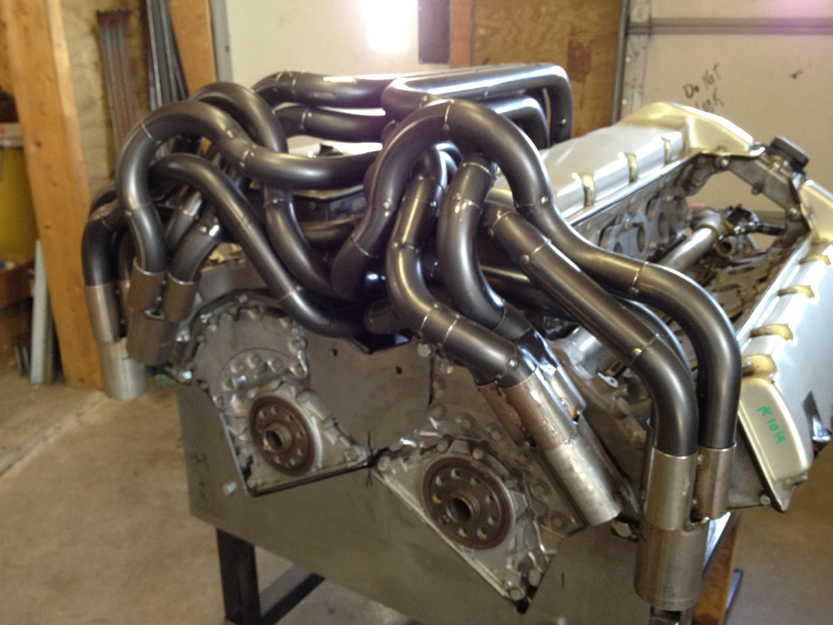
Once the basic drivetrain was established, Pelvit could then concentrate on what at least appears to any non-fabricator as perhaps the biggest challenge of all–fabricating 24 individual primary header tubes into four separate collectors that could then be joined into the final quad exhaust system.
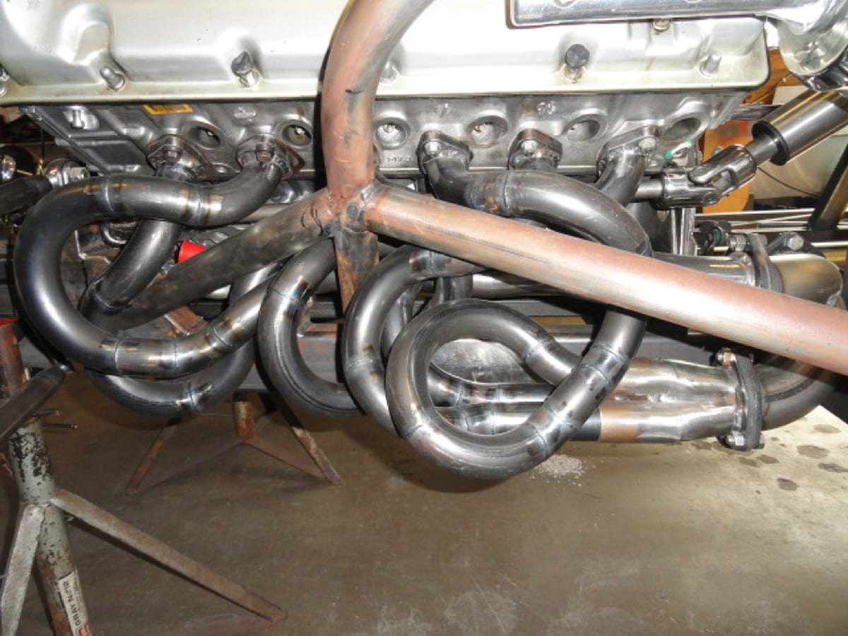
Have you ever tried to fit a pair of big-block Chevy headers back into their original box? We’ll bet Pelvit is really good at that because much of what he has accomplished with this 1957 is about wrangling 24 slithering header tube snakes into a 12-snake bag and not getting bit. How do you do that? The only other place we’ve seen this kind of packaging is on Bonneville streamliners with the skin removed. Pelvit is the master of the meandering tube.
Each primary tube consists of between five and eight (and sometimes more) individually tweaked tubes. Even with a pipe with just four sections, that’s five welded connections (counting the head flange) that have to be fitted, trimmed, and then carefully welded. It was a massive undertaking that required an overall plan. Pelvit routed a pair of three tubes on each side into two collectors that were then communized into a single collector for each bank. That created four separate collector pipes that were routed to a quad exhaust system with four mufflers. That’s a ton of tubing and days worth of welding.
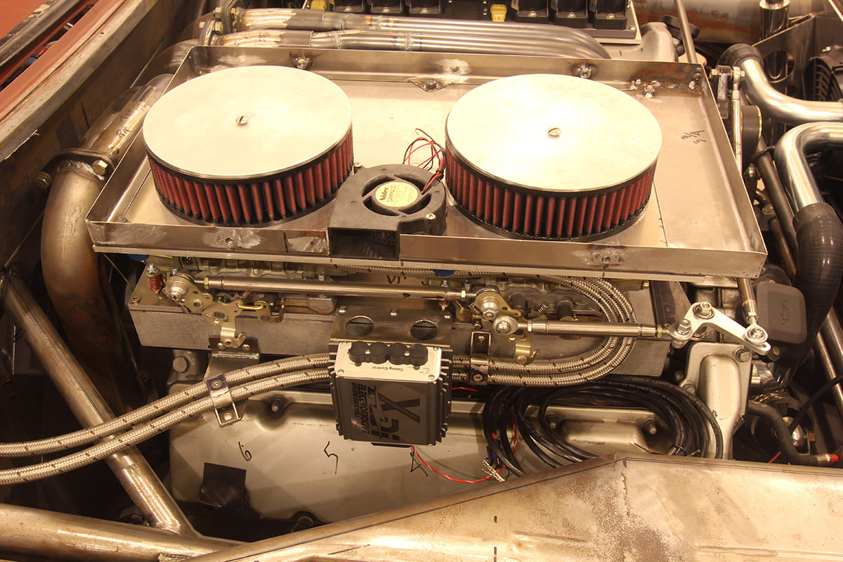
On the induction side, the pair of hot rodders desired a more traditional induction system with four 600-cfm Holley carburetors. This put the original EFI system out of a job, which included spark control. Since this was a distributorless EFI engine, Pelvit sought help from the Electromotive company in Manassas, Virginia. This company has been building EFI systems since the ’80s and had just the ticket for this pair of V-12 engines.
Running completely separate ignition systems for each engine, Electromotive creates a waste spark system. In this configuration for a V-12, the system uses only six coils and fires each one twice per 720 degrees of rotation. Each coil is connected to a pair of cylinders that are exactly one crank revolution apart. One cylinder is on the firing stroke while the other is on the exhaust portion. The spark plug on that cylinder fires but because it’s on the exhaust side of the four-stroke cycle the spark is “wasted” and no combustion occurs.
Each engine is tuned with the exact same initial and advance curves but they do operate separately. This was part left to chance since there was no easy way to test to ensure the engines would fire and run smoothly until the entire W24 package was assembled.
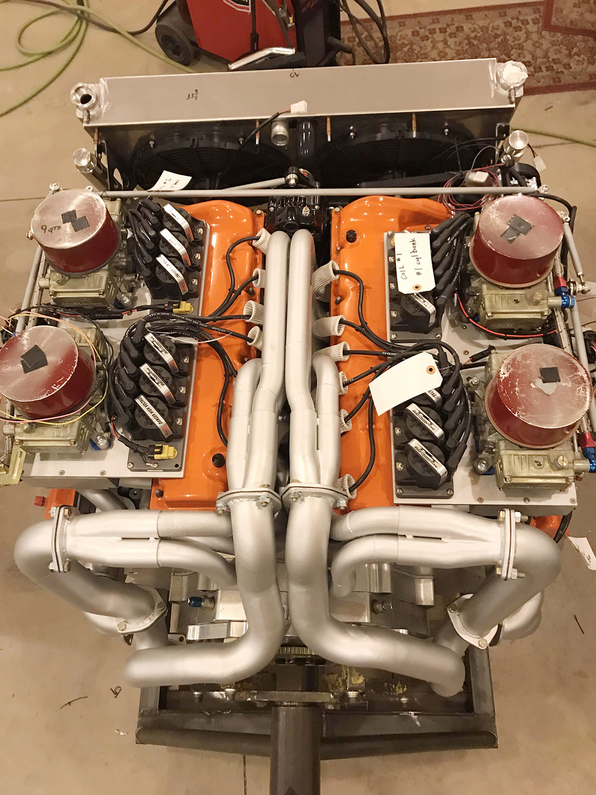
Pelvit constructed a test stand with both engines oriented as they would be in the car, including the dedicated cooling system and recently fired the engine(s) for the first time. It was almost anticlimactic as the engines started almost immediately and soon settled into a stable idle after some minor carb tuning. As you can imagine, the W24 has an exhaust note all its own that is somewhere between a whine and a distinctive growl. It revs quick despite spinning those two massive crankshafts and it sounds like it means business.
Kollofski was a bit concerned since in this short initial run the engines began to build heat even with all the electric fans running. They shut the engine down and began searching for a possible solution. That’s when Pelvit discovered he had left the cardboard protective cover between the radiator and the fans. A subsequent running revealed the coolant temperature barely exceeds the thermostat opening point.
Other small things that production engine builders are not typically concerned with include little things like the starter motor. With their original flywheels replaced by gears to blend the output, Pelvit had to adapt a single starter motor to the single flexplate. This meant the starter motor would have to be capable of hot starting at 656 ci. For that job, they sourced a killer starter motor from Meziere Industries that makes high-torque starters for monster displacement high-compression drag race engines. It cranks the W24 over effortlessly.
There’s still much to complete on the car as the engine now has to find its way back into the 1957 and to complete the myriad of small details needed to finally complete the car. But it’s closer than ever. Perhaps in 2021 we will see this beast terrorizing the streets of Northern Minnesota.