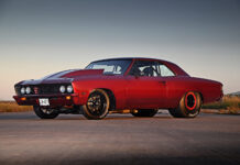
When our buddy Adan Resendez relayed the steering plight that his newly built Chevelle had suffered, we were initially relieved that he was able to safely limp the car to the shoulder of a residential road near his home. After initial inspection, however, our relief turned to terror as we began to unravel the heinous acts of mechanical ineptitude that slowly unraveled. What should have been a fairly simple, straightforward installation for any reasonably handy car guy turned into a nearly fatal mistake in Resendez’s ’67 Chevelle steering shaft assembly.
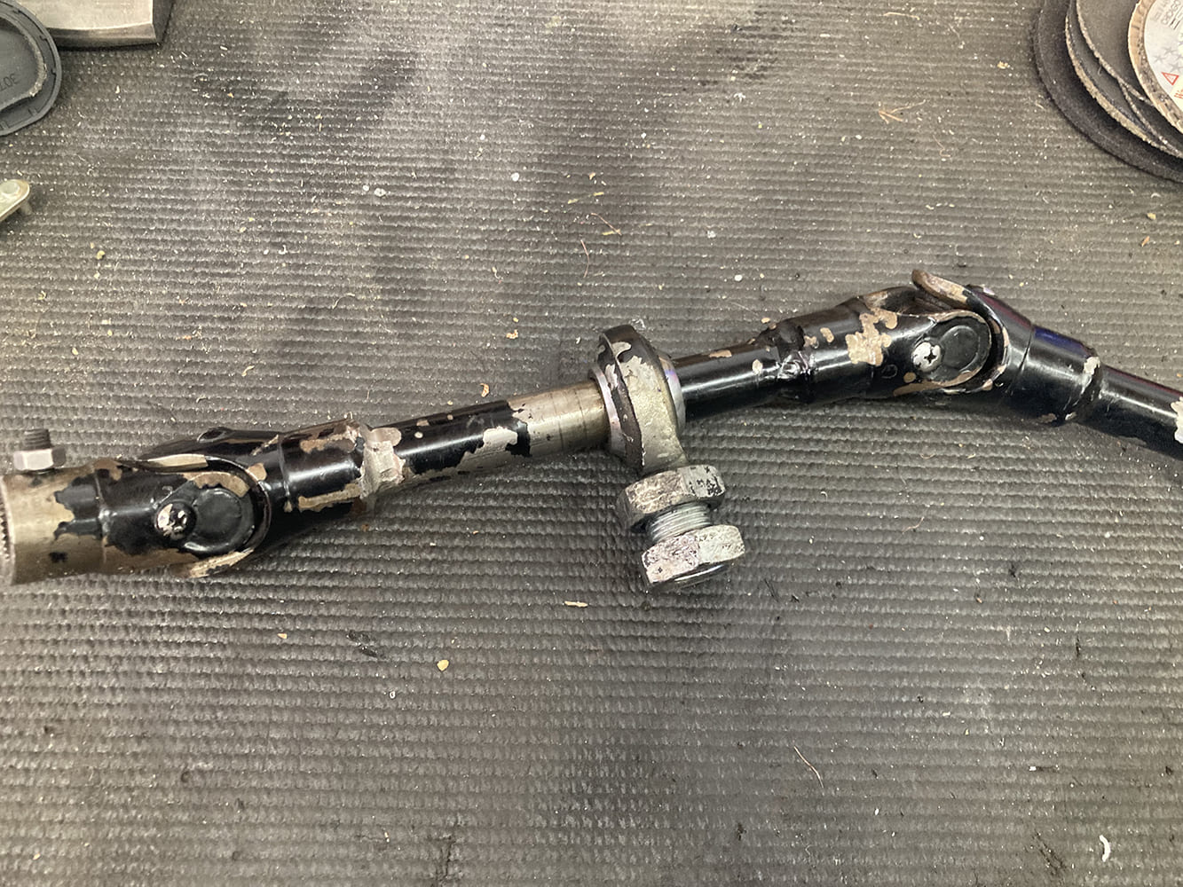
The steering linkage alone should have raised concerns. All the U-joints were welded to the shaft (poorly), so as to effectively isolate the support bearing permanently.
While it’s not uncommon to uncover shoddy work from time to time, this instance was one for the record books.
With our shock subsided, we shifted gears and began to develop a plan to get the old Chevy back on the road and safely, starting with quality U-joints and shafting and a proper method to secure the steering column that wasn’t. From there, we also addressed another issue we found: an incredibly noisy power steering system caused by an incorrect reservoir and exacerbated by its location.
When everything was said and done, Resendez was able to once again return his dream car to the road, with the added peace of mind that what nearly could have killed him has been sorted in the best (and safest!) way possible.
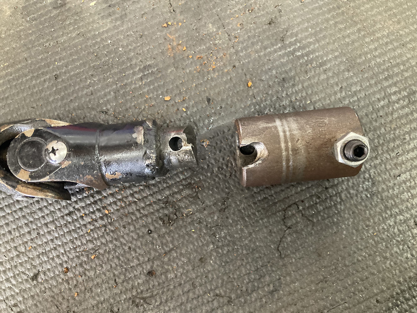
But the linkage alone wasn’t the cause of our steering woes; it was how the previous hack builders fixed the nub of the shaft welded to the uppermost U-joint on the steering column shaft. Apparently, the “rocket scientist” who originally did the install thought it was enough to simply pin the two together with, presumably, a roll pin; however, it was not to be found.
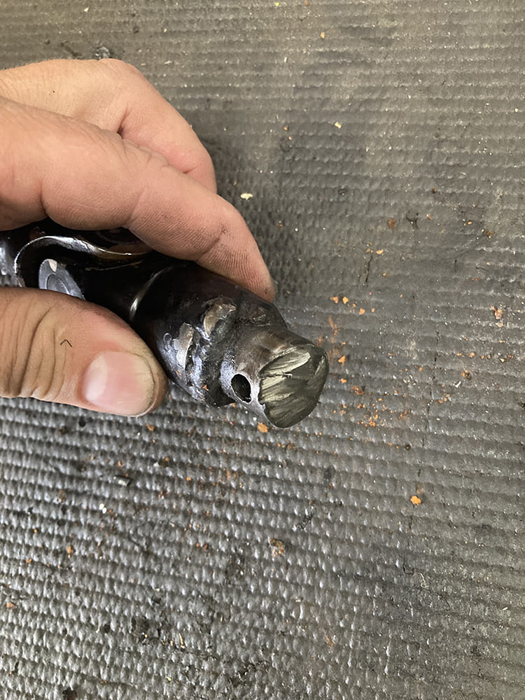
Closer inspection of the fab master’s work shows the amount of care that went into creating a nice, square, clean cut on the end of the nub shaft.
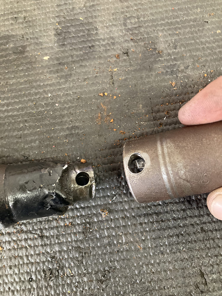
Why he didn’t simply use a properly sized U-joint to go from the second shaft directly to the steering column is anyone’s guess; instead, he opted to adapt the nub shaft to the steering column using a coupler. Note the care used in drilling out the roll pin hole! This is ultimately what failed and resulted in a total loss of steering control. Thankfully, it happened at low speed in a residential neighborhood. Had this happened in traffic or on the highway, it may have resulted in a multiple-fatality situation.
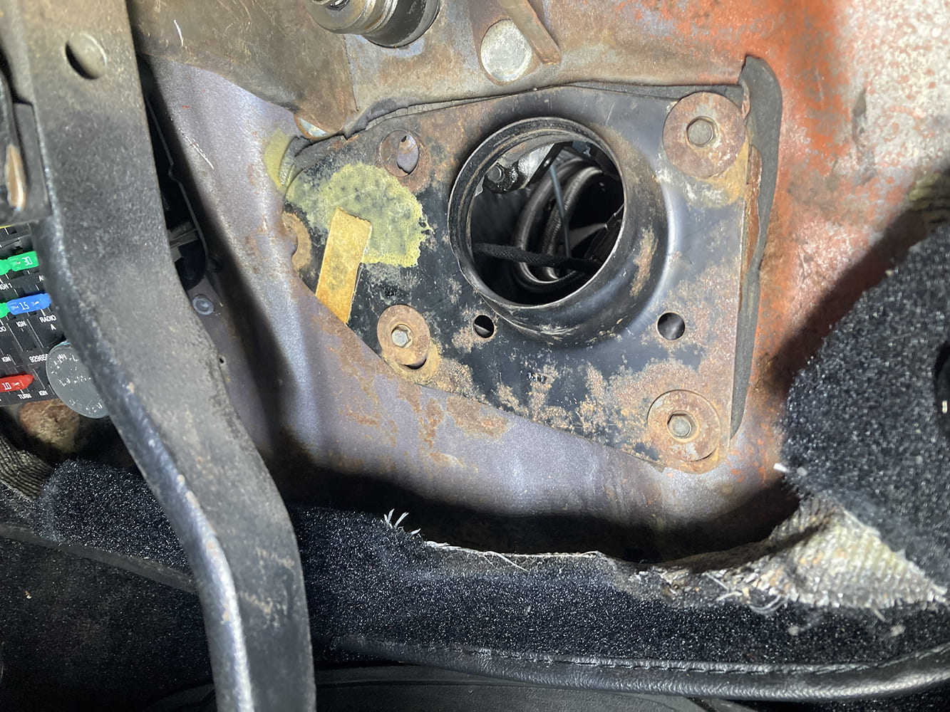
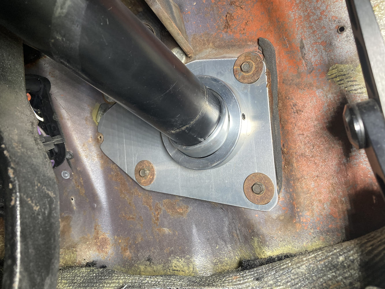
Adding insult to injury, the bottom of the steering column lacked a single point of support, leaving it to freely bounce around in the stock firewall plate, supported only by the singular dash bracket at the top.
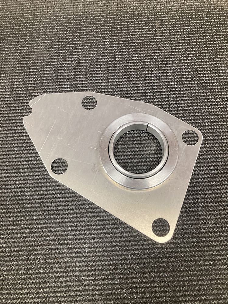
A proper method to support the bottom of the steering column is an absolute must, and this Swivel Floor Mount (PN FR20101CH) from Flaming River fits 1964-67 Chevelles equipped with an aftermarket steering column.
Bolted in place using the factory hardware, the steering column is now located securely in place.
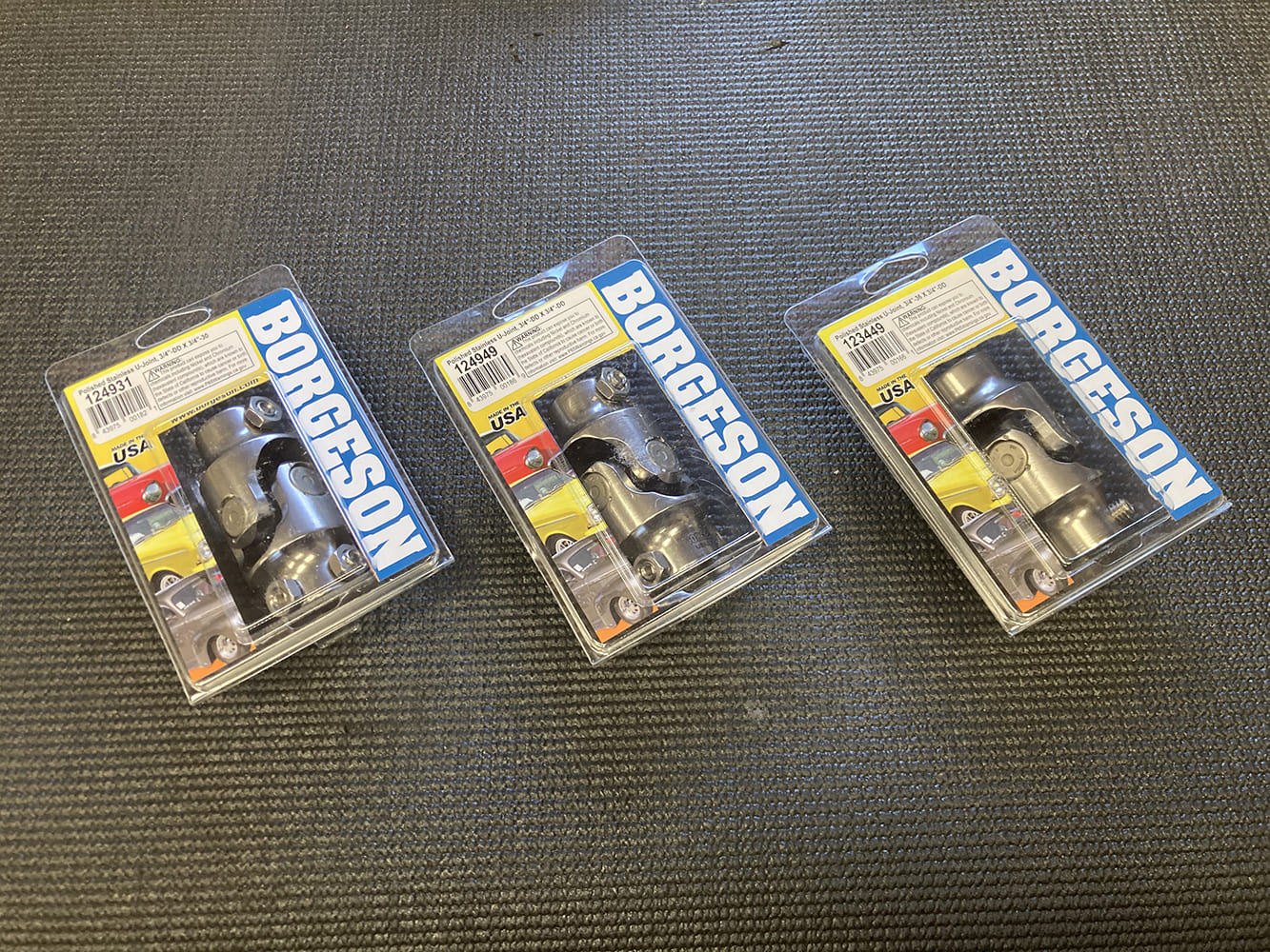
To safely mate the column to the power steering box, we used proven hardware like these U-joints from Borgeson. The previous installation used three U-joints, but we were fairly certain we could make it happen in two. This would certainly simplify the situation.
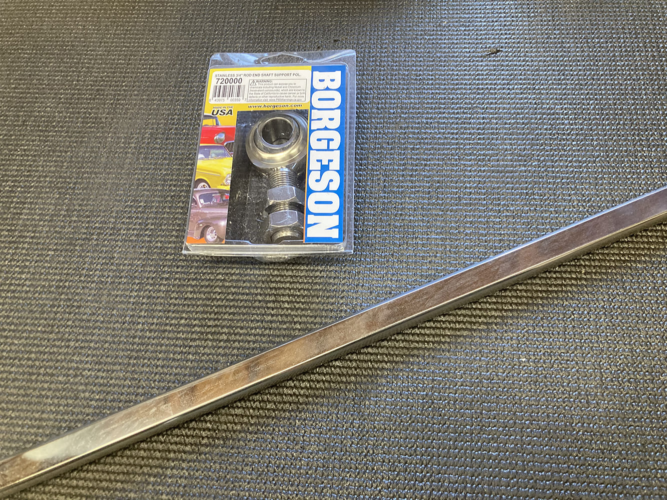
We used a 36-inch length of polished stainless steel DD shaft (PN 429436) from Borgeson as well. Anything more than two U-joints requires a support bearing to prevent any binding in the linkage, so we picked up one of those from Borgeson (PN 720000), just in case.
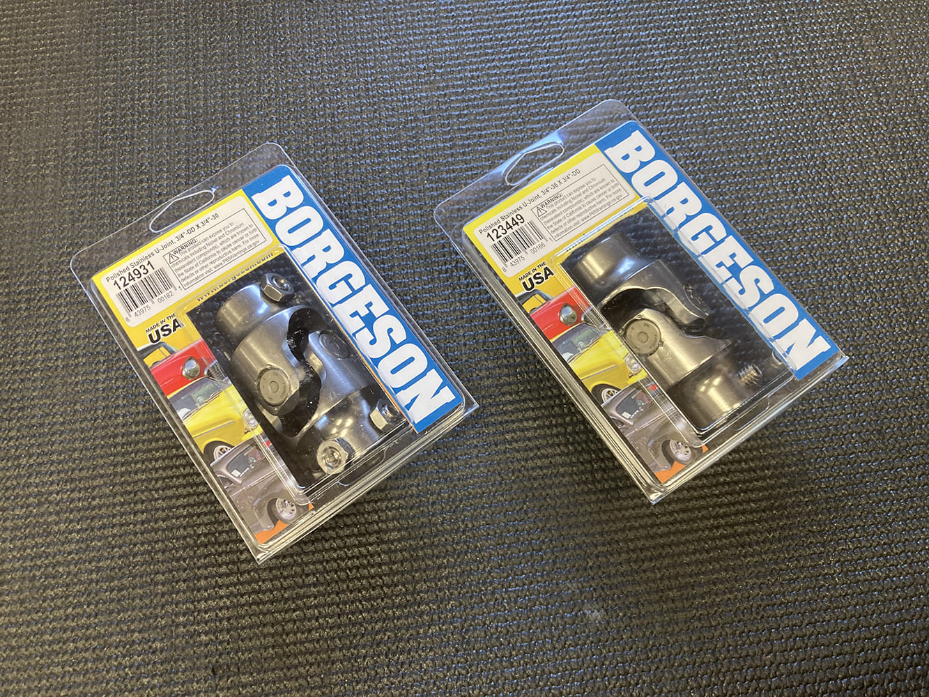
Turns out our initial estimates were correct and the Chevelle will only require two polished stainless U-joints; a DDx3/4-30 (PN 124931) and a DDx3/4-36 (PN 123449).
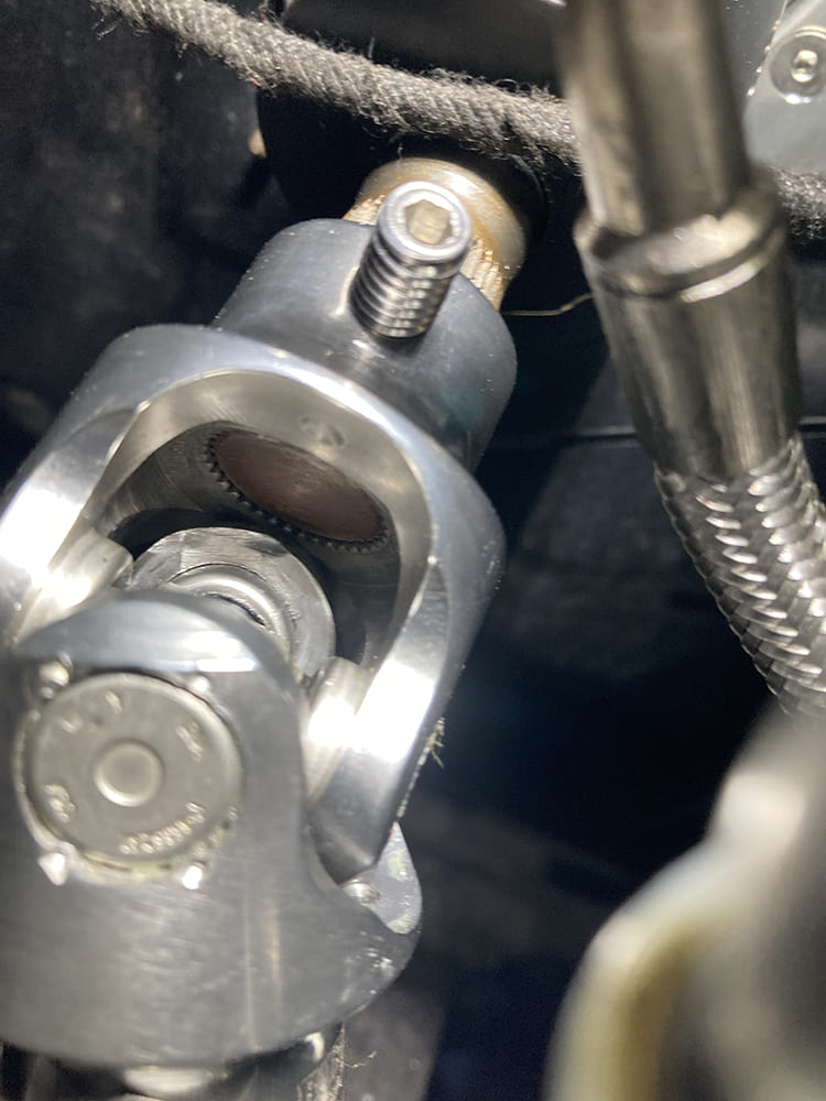
The DDx¾-36 U-joint will mate on the column end …
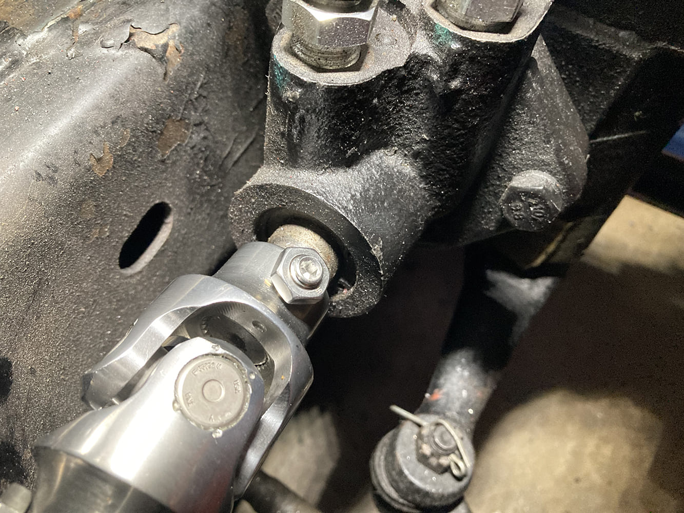
…while the DDx3/4-30 mates to the box.
Before we can measure and cut the DD shaft to connect the two U-joints, we need to be sure that both are fully seated on their respective splined shafts.
Note that both shafts are flush with the inside of their respective U-joint half to ensure proper engagement without creating any bind with the U-joint itself.
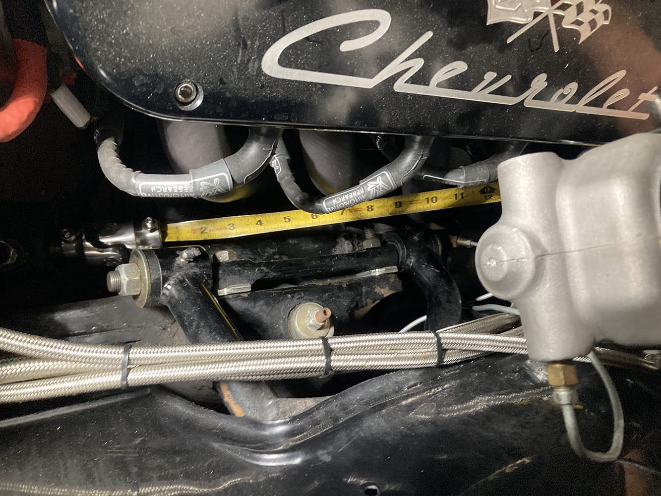
With the U-joints properly installed, the distance between the two can be measured and the DD shaft cut to length.
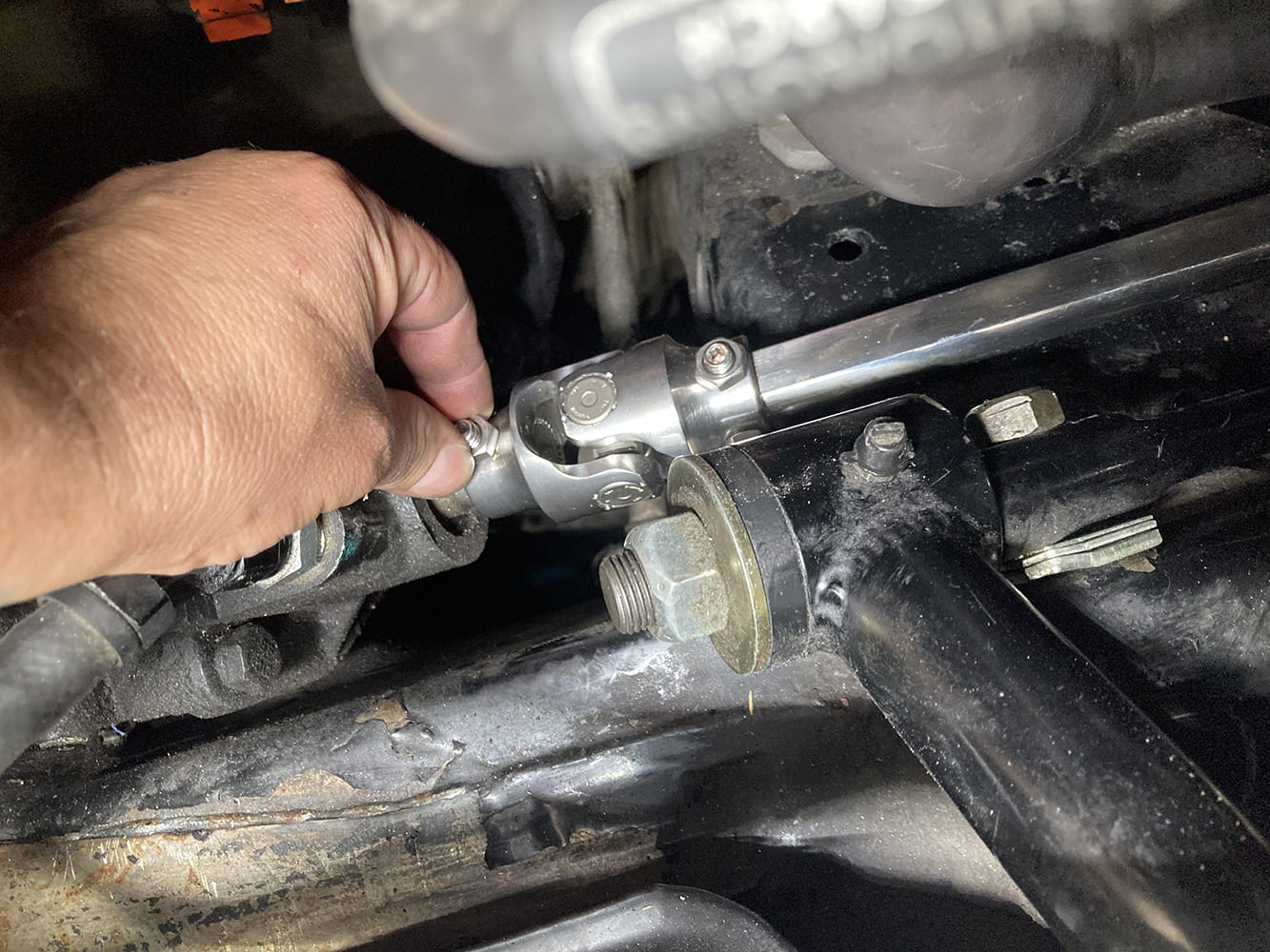
Next, the assembly is installed hand-tight and is checked for any fitment issues.
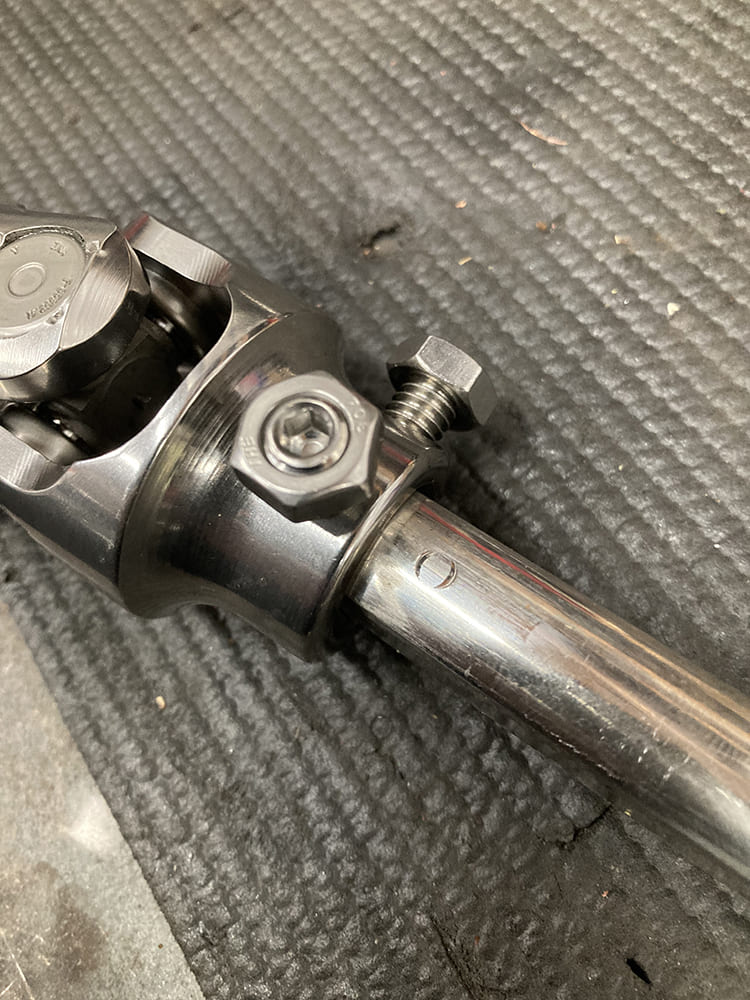
Satisfied, each pinch bolt is tightened to mark the DD shaft for dimpling.
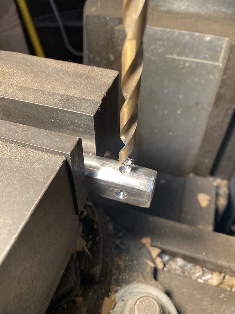
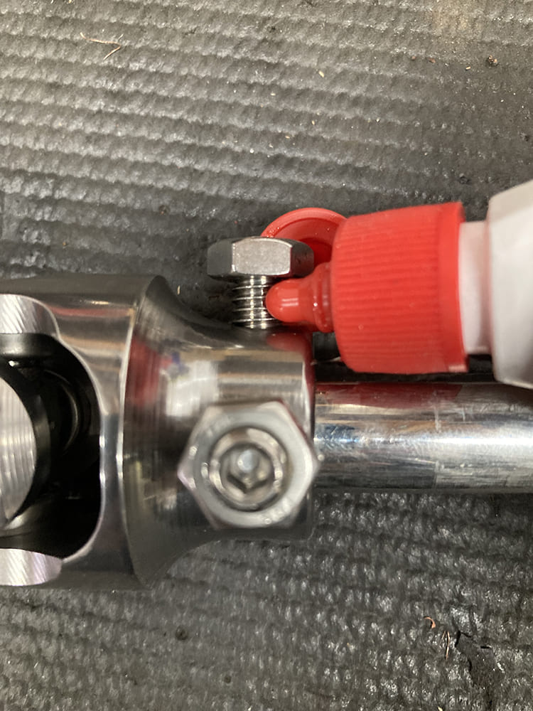
A ¼-inch drill bit is used for this process, which ensures the pinch bolt has plenty of purchase to bite into, preventing the assembly from coming apart.
After the dimpling process, permanent thread locker is applied to the threads of the pinch bolt and the locking nut.
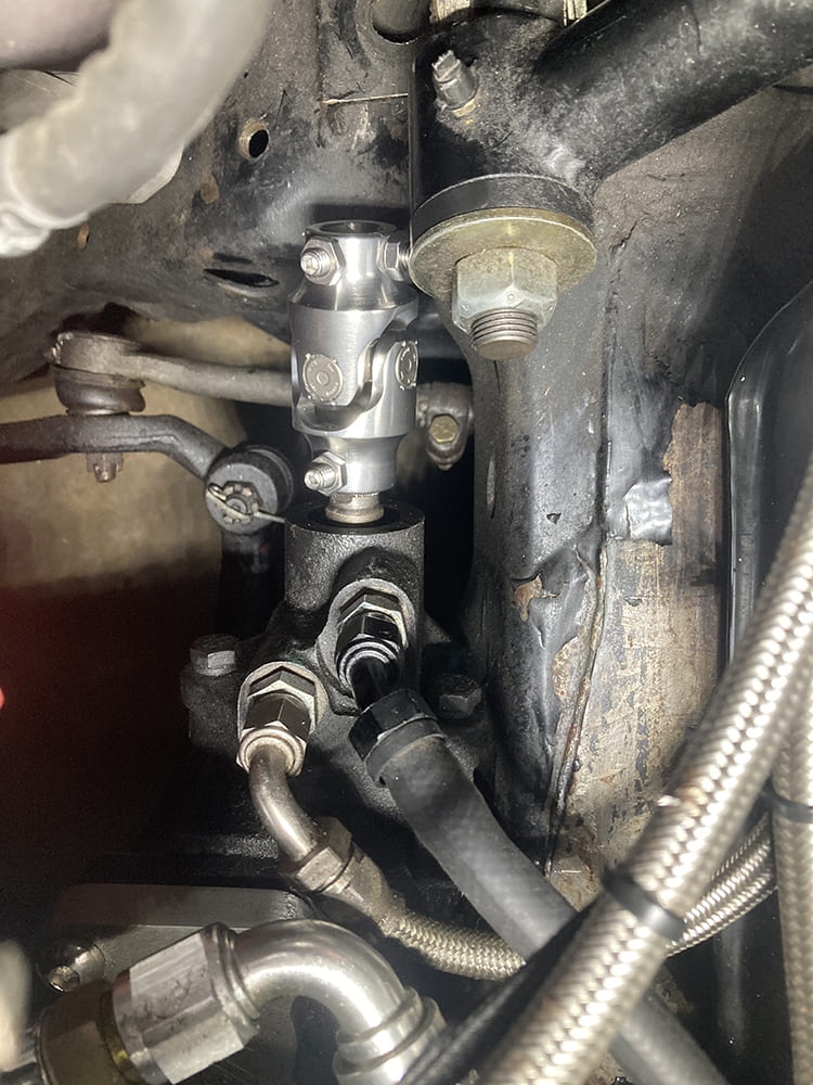
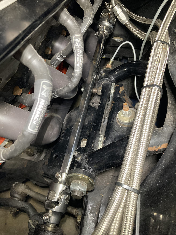
The finished steering linkage is a simpler and safer design than the previous iteration.
Aside from the steering linkage issue, the Chevelle also suffered from an egregious amount of noise emanating from the steering gear. Since the power steering system also served to provide braking assistance via Classic Performance Product’s HydraStop system, we contacted the guys over at CPP to see what they thought might be our issue. Turns out an incorrect reservoir along with its mounting location was the source of our issue.
In addition to the reservoir, the existing stainless steel lines were suffering from ablation and fraying…
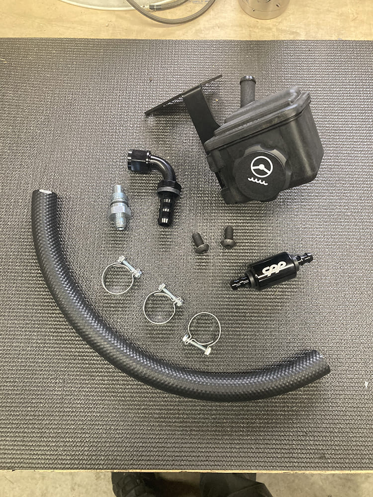
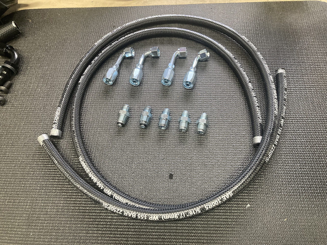
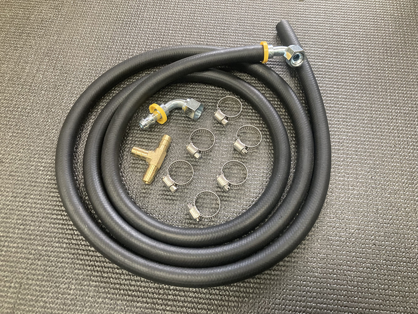
…so after consulting with the CPP gang, we opted to replace the entire plumbing side of the coin starting with this high pressure braided hose and steel fittings.Their LS Engine Remote Reservoir Kit (PN CPLSRRM), Push Lock Power Steering Filter (PN PO-OF6), and HydraStop Rubber Hydraulic Hose Kit (PN HAHK-R) will provide all the parts we need to solve the growl in our system.
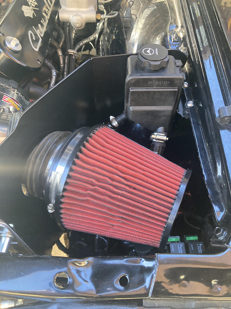
To prevent further issues in the HydraStop system, we opted to mount the reservoir as high as possible. We chose a location in the fresh airbox next to the air cleaner for easy access and ideal location in the system.
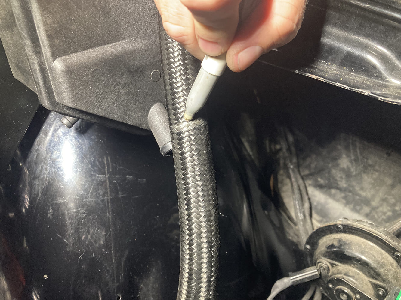
Whether high- or low-pressure, every line in the CPP hose kit needs to be measured, cut, and assembled and assembled with its respective fitting and blown clean to ensure its free of any debris before installation.
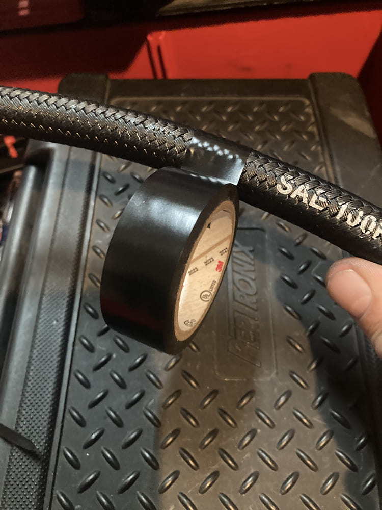
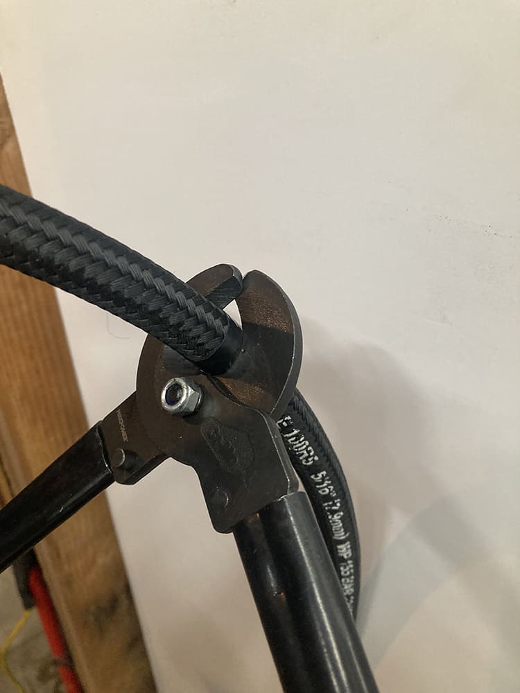
Electrical tape is wrapped tightly around a black braided hydraulic hose to prevent fraying before cutting.
We used curved-jaw cable cutters. They provide excellent leverage and make clean, perpendicular cuts.
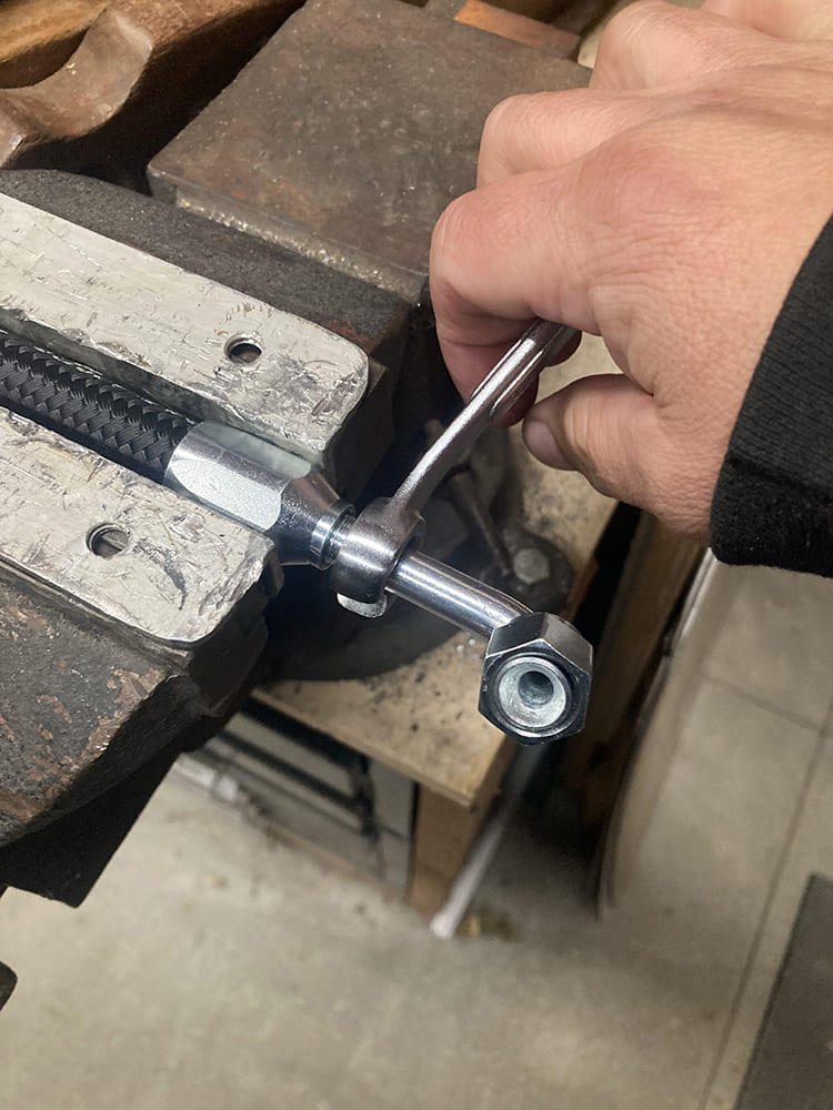
A 90-degree hose end fitting is assembled onto the braided line after clamping the socket in a vice.
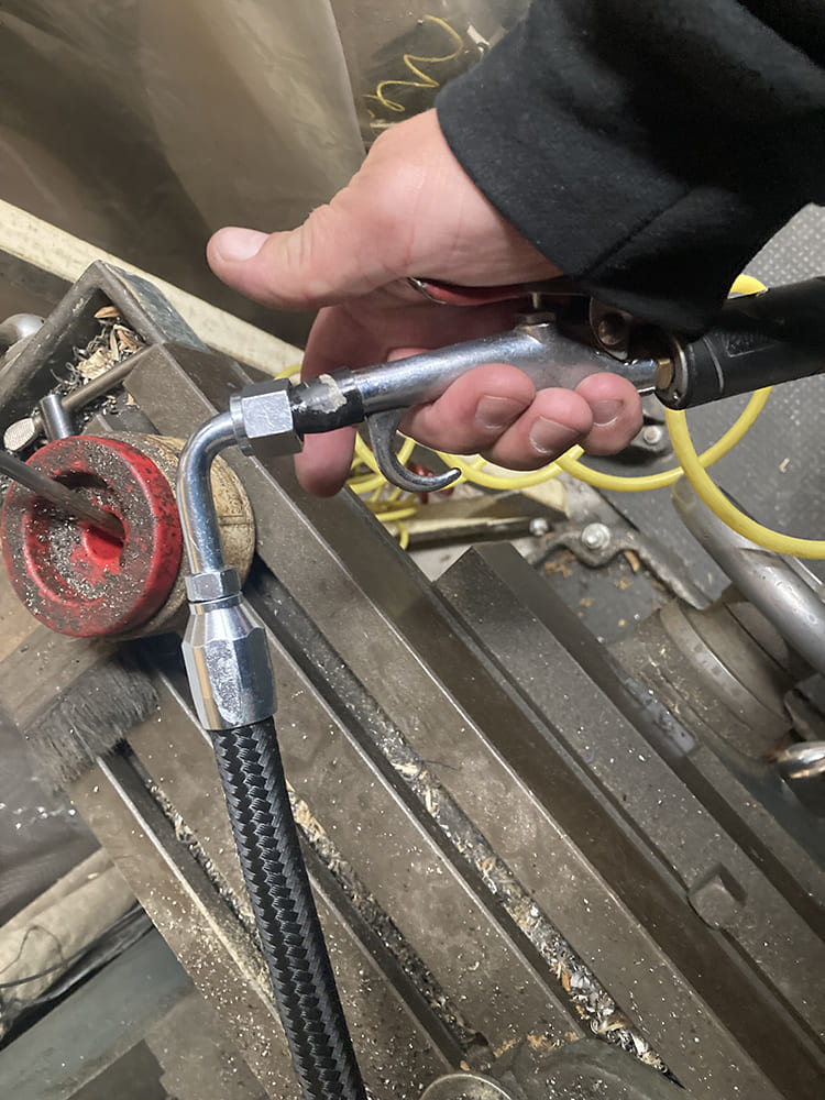
We blow compressed air through each line after assembly to clear any debris.
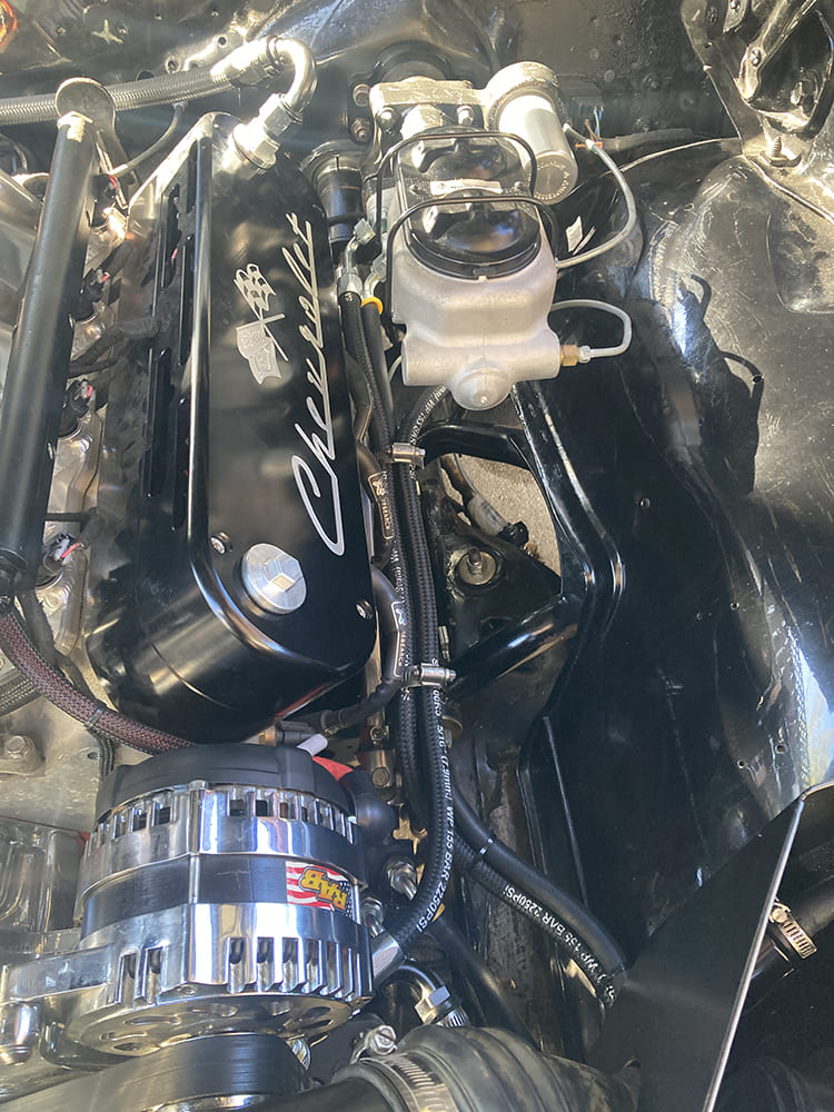
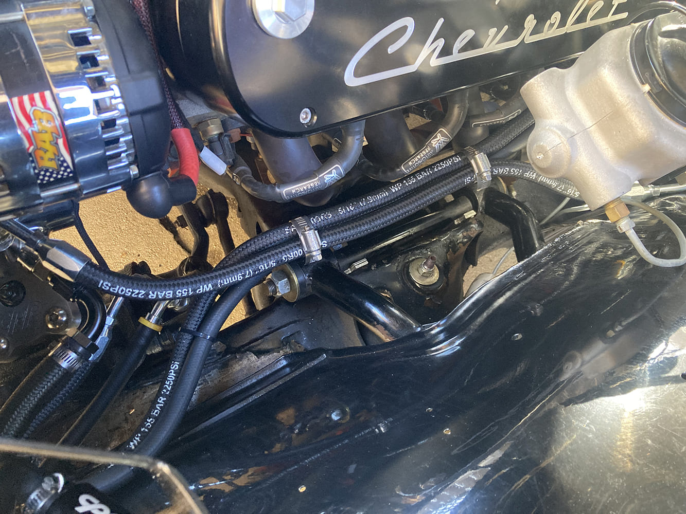
The result is a clean installation, with every line clear of heat or abrasion and mounted firmly in place.
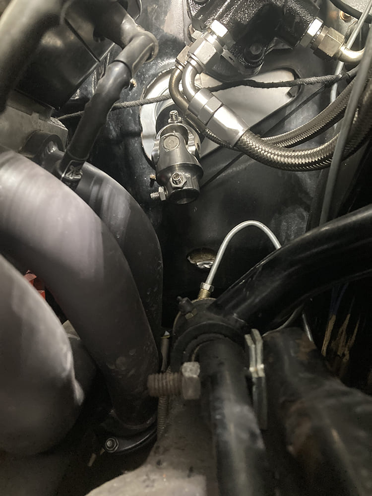
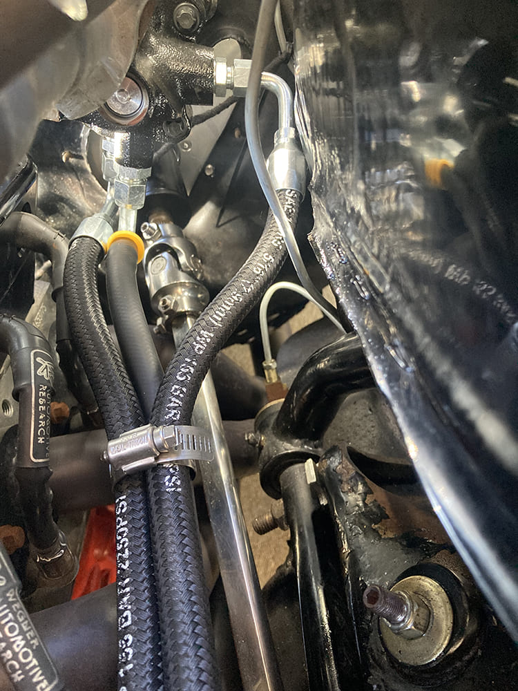
Here’s a close-up of the installed steering shaft at the steering column, as well as the newly-made high and low pressure power steering and hydroboost lines.
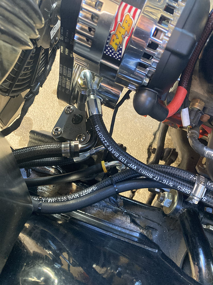
…and here’s the other end of the power steering and hydroboost hoses connected to the power steering pump and steering box.
The black high-pressure power steering hose blends in nicely with the engine bay.
We use cookies to ensure that we give you the best experience on our website. If you continue to use this site we will assume that you are happy with it.