


By Jeff Smith – Images by the Author
Rocker arms are one of those component topics that don’t get their share of attention. For performance engines, there are some important considerations that might alter your perception of these simple devices. For this story we will focus on the small- and big-block Chevys as well as the LS powerplants. Over the years, the design of a basic rocker arm has evolved and, as you will see, for the better.
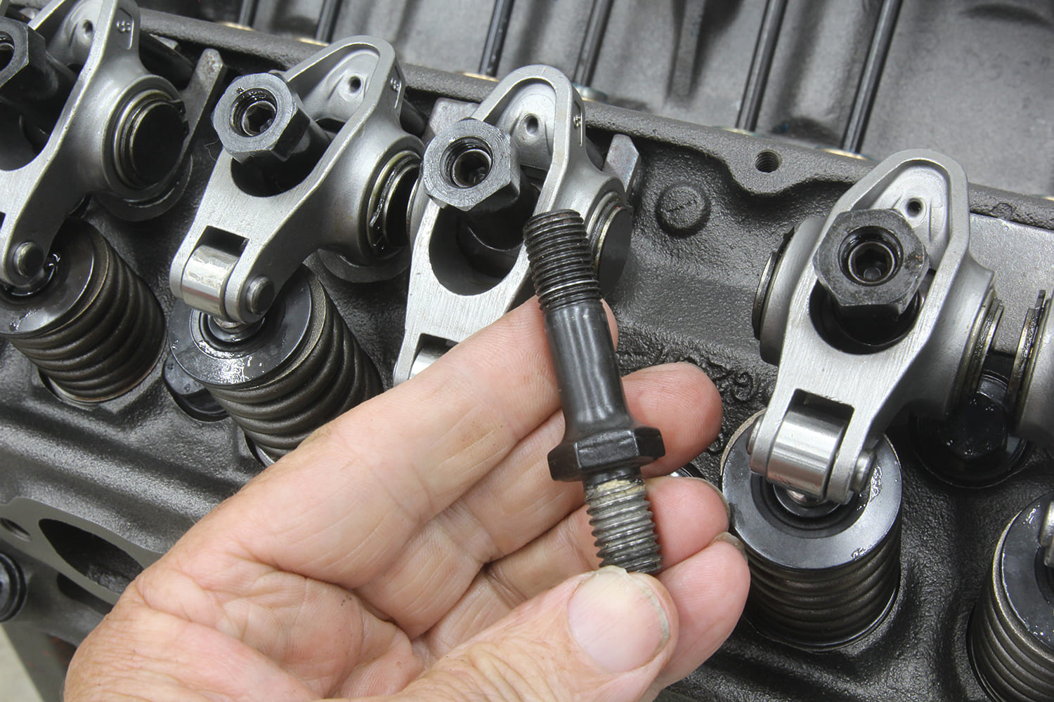
From the beginning in 1955, the small-block Chevy fell under scrutiny for its unusual stud-mounted stamped steel rocker arms. Until that point, most production engines with overhead valves relied on shaft-mounted rockers. An individual rocker mounted on a stud was less expensive to build and eventually spawned an industry.
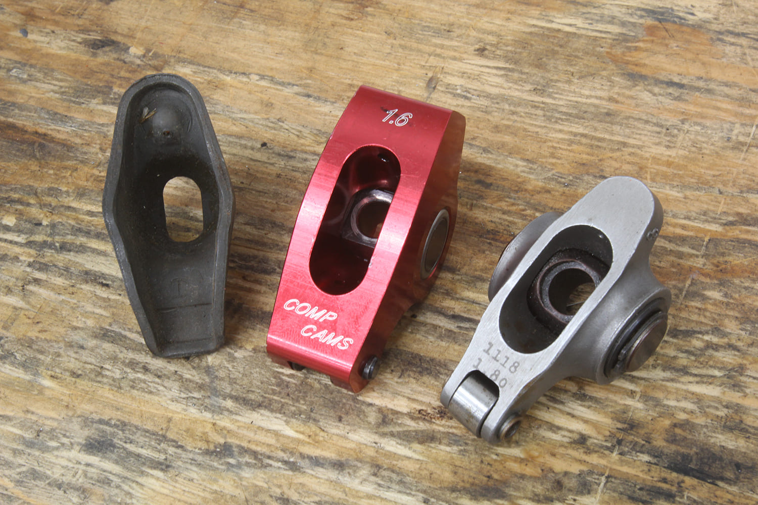
Chevy’s original stamped steel rocker is still a reasonable budget choice for near-stock engines, but we won’t spend much time with these components since aftermarket aluminum and steel roller rockers offer multiple benefits both in terms of improved power, lower oil temperatures, and greater durability.
Engine application will dictate the kind of rockers and ratios used. For mild performance applications, stock or aftermarket stamped rockers can do the job but ratio consistency is an issue. We once tested 32 stock stamped small-block Chevy rocker arms and discovered not one measured 1.5:1 ratio at half lift. Most fell into the 1.47:1 to 1.48:1 range with a few at 1.46:1 and a couple at 1.51:1. We matched eight 1.48:1 rockers for the intake side and noticed that the idle vacuum improved slightly with this change.
If stamped rockers are in your plans, we’d recommend using rockers with milled ball inserts as they provide better lubrication. Plus, it’s a good plan to use a small die grinder to eliminate the exposed sharp edges on the top of the pushrod oil hole. This will minimize rocker failure from a stress crack. Beyond that, performance engines really do benefit from aftermarket roller rockers both from reduced friction and more accurate ratios.
The basic design of the rocker arm is to not only convert cam lift into valve motion but at the same time to multiply lifter motion at the valve with a ratio. The traditional small-block Chevy rocker ratio has always been 1.5:1 with the big-block Chevy at 1.7:1. Think of a rocker arm as nothing more than a simple exercise in leverage. With a longer lever length on the valve side, this moves the valve side of the rocker a greater distance, which increases valve lift compared to lift created by the cam lobe and lifter.
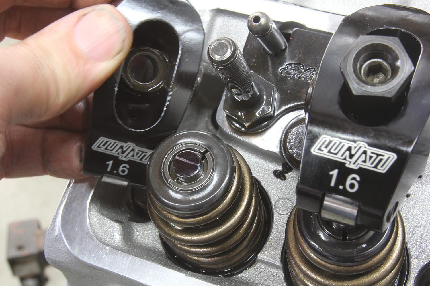
Increasing the stock rocker ratio on a small-block from 1.5:1 to 1.6:1 is achieved by shortening the distance between the pushrod cup and the rocker centerline. This is necessary because the distance from the centerline of the rocker arm stud to the valve centerline is a fixed length.

The effect of rocker ratio is to multiply the lobe lift to increase valve lift. With an intake lobe lift at 0.350-inch and a 1.5:1 rocker ratio, this will theoretically produce 0.525-inch of valve lift. Increasing the ratio to 1.6:1 will bump the maximum valve lift to 0.560—an additional 0.035 inch.
Beyond just lift considerations, a change in ratio also affects duration. The cam’s opening and closing numbers will not change—that’s established by the cam lobe. However, once the lobe initiates lift, duration measured at the valve will increase slightly because the rocker is accelerating the valve at a greater rate. These changes are small, but measurable.
One downside to increasing rocker ratio is the additional load placed on the lifter and pushrod. This is because while the higher ratio multiplies the lift curve, the change in pushrod position on the rocker reduces the leverage on the pushrod side. This increases the load. This is something to consider when breaking in a new flat-tappet camshaft. A lower rocker ratio will reduce the load on the lifter and camshaft.
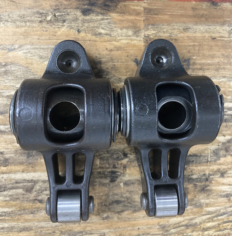
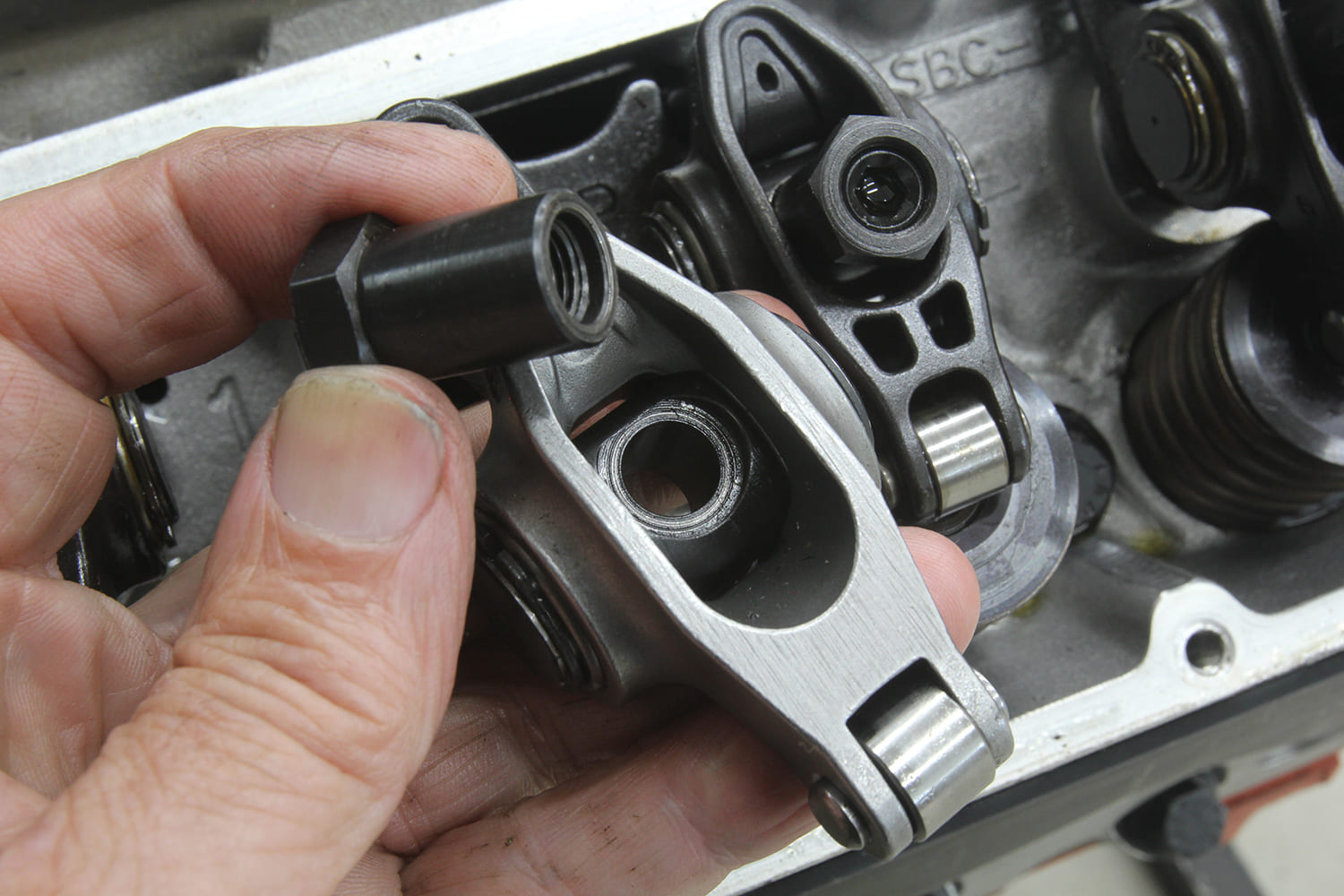
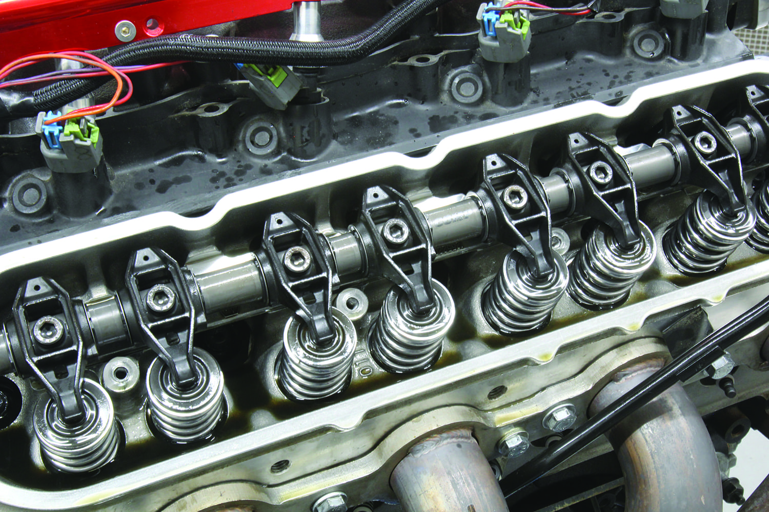
The 21st century version of the stock stamped rocker story is the new-generation LS rocker arm. Most enthusiasts already know that the LS engine dramatically increased the rocker ratio to 1.7:1, which means with the same 0.350-inch lobe lift the valve would now see 0.595 inch of lift. The LS rocker system also differs from the stud-mounted small-block Chevy in that lash is not adjustable. Instead, this valvetrain is designed as a net lash system where the rocker bolts to the head. The hydraulic lifter preload is set by altering the length of the pushrod.
The LS rocker is an investment cast steel for increased durability using a needle bearing trunnion with a very compact and light rocker body. While the trunnion employs needle roller bearings, the pad that contacts the valve tip is not rollerized. Stock LS rockers fitted with a trunnion bearing upgrade with better bearings can be used with camshafts with lift up to slightly more than 0.550 inch.
It might seem like a good idea to just push to a 1.6 or 1.7:1 rocker ratio for a mild street small-block Chevy to quickly bump the valve lift. While this is an option, there are sometimes unintended consequences that accompany this action.
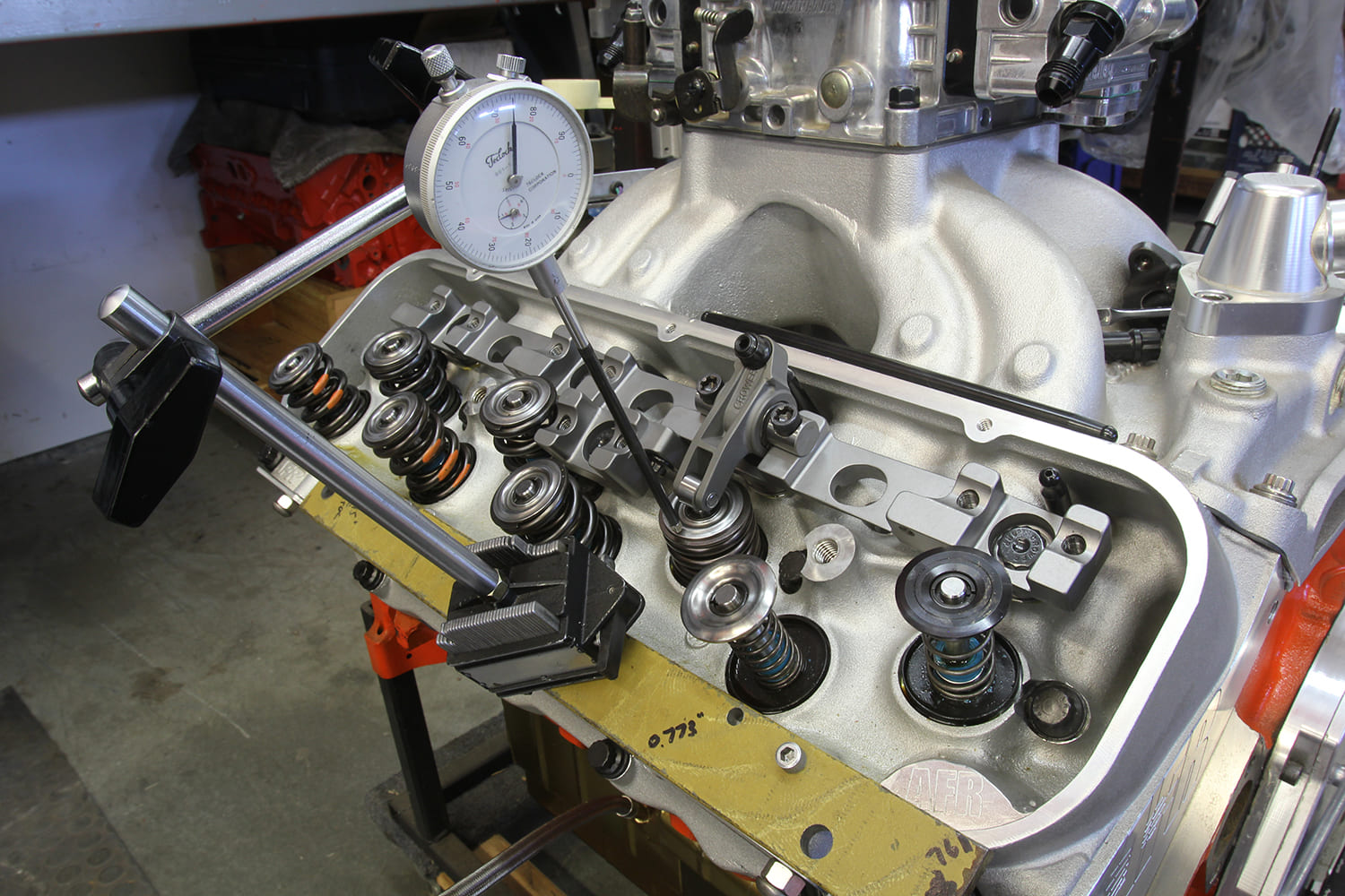
Increasing the rocker ratio adds lift throughout the entire valve lift curve. Keep in mind that piston-to-valve clearance is tightest not at maximum lift, but actually at 10 degrees before top dead center (BTDC) for the intake valve and 10 degrees after top dead center (ATDC) for the exhaust. Most mild street engines will likely have plenty of piston-to-valve clearance, but it is always a good idea to check this clearance before starting the engine. That additional lift could also cause retainer-to-seal clearance issues or potentially coil bind the valvesprings. Both of these must be checked before adding the rocker ratio.
For street small-block Chevys with mild cam durations of roughly 210 to 220 degrees at 0.050 or shorter, these cams often accelerate the lifter very quickly in order to enhance power despite the short duration. If you add rocker ratio, not all these lobes will react well with mild spring pressures. We witnessed a mildly cammed small-block suffer from valve float as early as 5,500 rpm when we bumped the rocker ratio from 1.5:1 to 1.6:1. The solution for an issue like this would be to use a better valvespring or a combination of a stiffer spring and a lighter retainer to offset the effects of those higher valve acceleration rates.
This might be a good place to also point out that as the rocker arm rotates through its lift curve that the rocker tip travels in an arc across the valve tip. This movement also affects the true rocker ratio. There are multiple approaches to dialing in rocker arm travel based on pushrod length. This topic is beyond the scope of this story to address except that it is certainly worth close inspection.
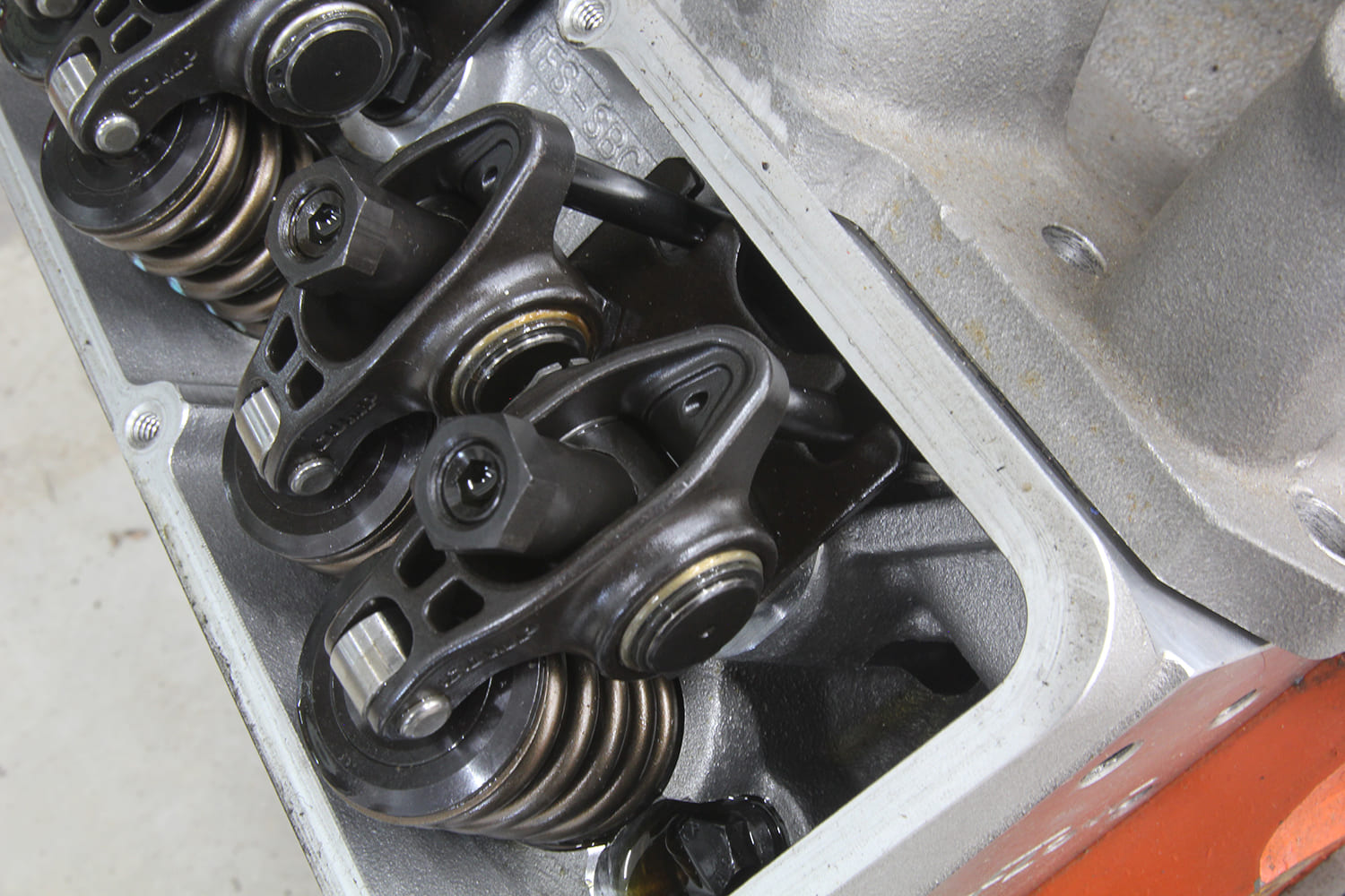
Material choice for rocker arms is another area worth investigating. The original stamped steel rockers were durable to a point but when roller rockers first began to appear they were almost entirely aluminum and slightly larger than their stamped steel counterparts. Aluminum isn’t as strong as steel and aluminum rockers can suffer from deflection, especially when used in conjunction with high spring pressures.
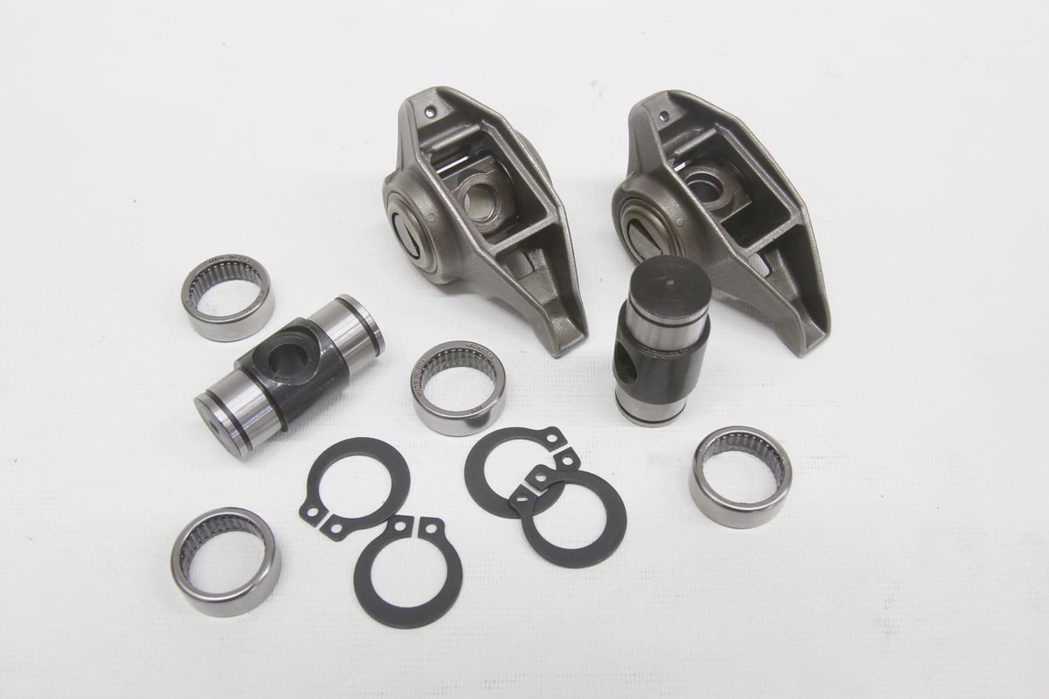
The better stud-mounted versions in use today are steel rockers that have been CAD-designed to reduce weight, especially around the rocker tip where weight is affected by high acceleration rates from both cam lobes and rocker ratio. Even at a reasonable 6,000 rpm, a rocker arm will complete 50 valve lift cycles every second!
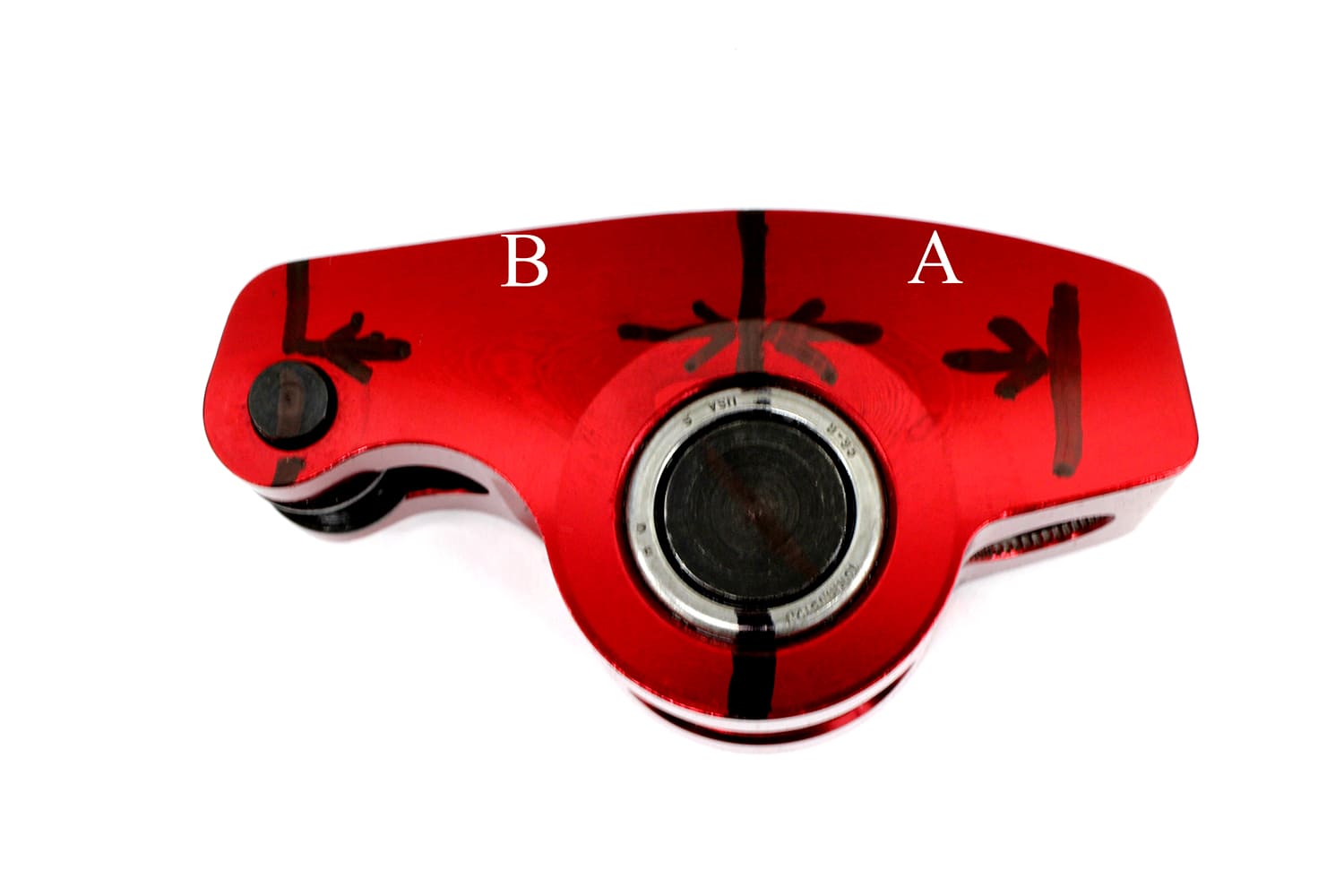
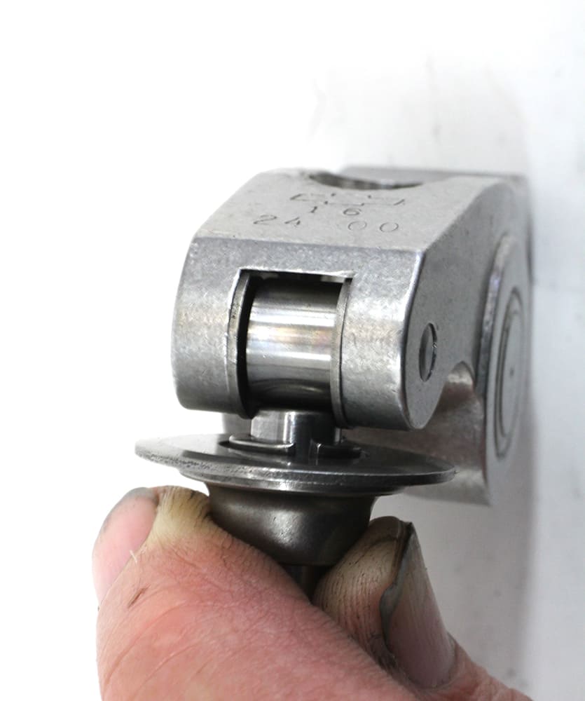
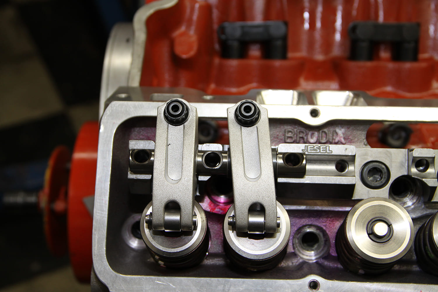
When engine applications spin the engine at speeds above 7,000 rpm with big-lift camshafts pushing against 600-plus pound open spring pressures, a stud-mounted rocker system is approaching the ragged edge of its abilities. This is where a modern, aftermarket shaft rocker system reveals its true benefits. Way back in the early 1970s Dan Jesel realized that a major limitation of the stock stud-mounted rocker system was the small-block’s short pivot length, which is the distance from the trunnion centerline to the center of the roller tip. This shorter pivot length transcribes a wide arc across the valve tip, which causes a scrubbing action that costs horsepower.
Jesel’s solution was to eventually build a shaft system that allowed him to relocate the rocker arm’s trunnion centerline to increase the pivot length. This reduced the scrubbing action of the rocker tip across the valve tip, which is then multiplied by the load of a higher rate valvespring.
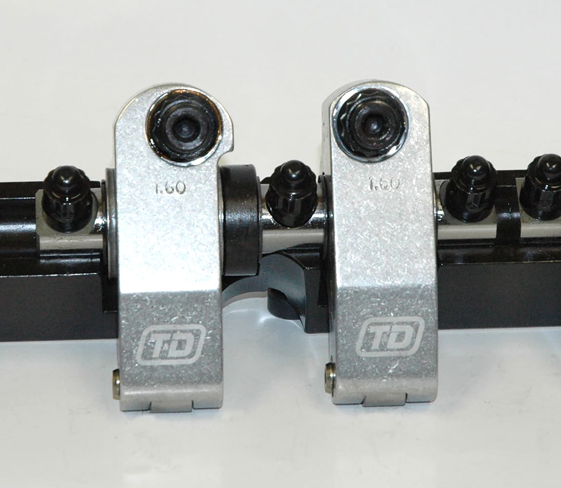
Jesel’s innovation has created an entire sub-industry of shaft rocker systems especially for the small- and big-block Chevys. The most common approach is not to use a single large shaft similar to 1950’s engines but instead to use custom stands using the original rocker stud locations to mount paired rockers using an abbreviated shaft.
This design offers multiple advantages that include reduced rocker tip travel across the valve tip due to the longer pivot length, improved accuracy of the rocker ratio, drastically reduced rocker arm deflection, which is lost valve lift, and generally much more efficient valvetrain operation.
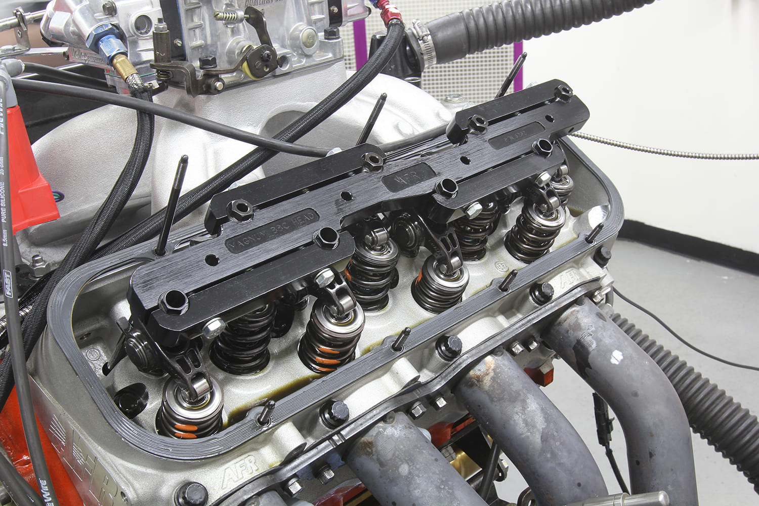
Of course, all this additional technology comes at an increased price but companies like Jesel, T&D, Comp Cams, and many others offer entry-level systems like the Jesel Sportsman systems intended for a wide range of stock and aftermarket cylinder heads.
Bigger ports and more-aggressive cylinder heads have also pushed the boundaries of valvetrain components with offset rocker arms that have become almost common in many performance circles. Offset roller lifters help to relocate the pushrod especially when matched with offset rocker arms. While there are some stud-mounted offset rocker arms available, this is an area where shaft rockers really shine.
Offsetting the rocker arm pushrod position imparts a lateral or sideways thrust into the rocker that can cause durability problems. Shaft systems can accommodate a certain amount of this offset and the twisting-style load. This is certainly an area where input and guidance from a professional engine builder would be of great importance.
Application is again the big arbitrator when it comes to a builder who might want to invest in a shaft rocker system. Competition on the track will always demand more horsepower from any engine but beyond drag racing there is tremendous opportunity for improved power and durability with a shaft system for engines engaged in Drag Week–style racing, autocross, track days, and other forms of competition where optimal valvetrain control at high rpm is essential.
As you can see, there is much to ponder when considering what type of rocker system to use in your engine. The good news is there are plenty of opportunities to get it right—the first time.
Check out this story in our digital edition here.