

A Quick-and-Easy Way to Measure Driveline Alignment
By Jeff Smith – Photography by the Author
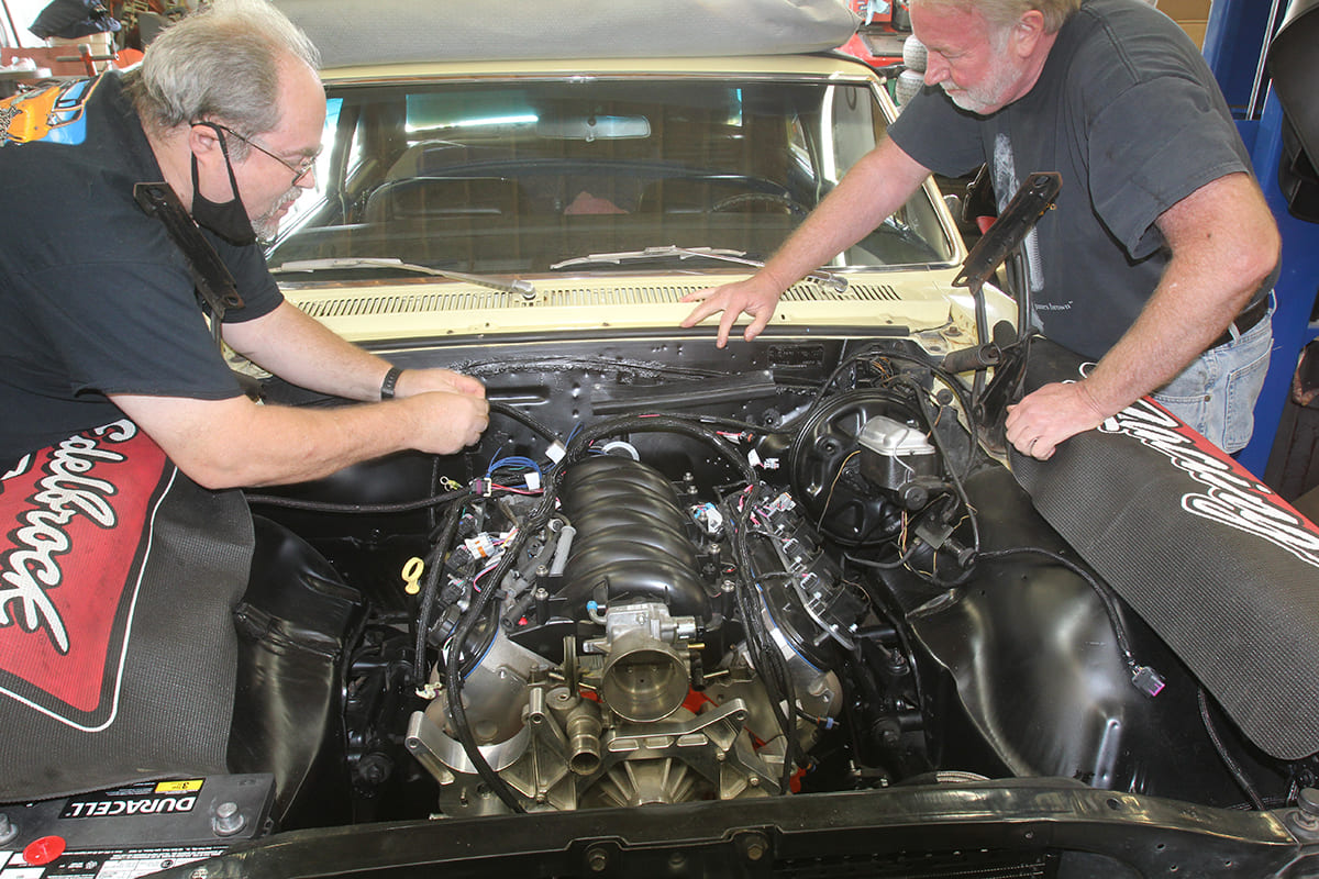
Engine and driveline swapping has long been a staple of building performance cars since the first rodders began swapping parts in the back of a blacksmith’s shop. Today’s market is full of LS swap parts, upgraded transmissions, and a myriad of rear axle opportunities. But along with all this parts customizing is the reality of ensuring all these parts work together, so your upscale machine sings along nicely on the highway.
One area that is universally overlooked is the link between the transmission and the rear axle. Sure, you spec’d the length of that custom driveshaft right down to 1/8 inch and it now fits snugly in between the engine and rear axle. But is the angle correct? Just because the driveshaft doesn’t vibrate or rattle the inside rearview mirror off its mount on deceleration doesn’t mean the driveshaft angle is correct. It’s really something that should be verified.
To minimize the confusion around measuring the driveline operating angle, TREMEC has come up with a slick smartphone application to measure and compute the operating angles for you. It turns out that a proper operating angle has a very specialized set of requirements.
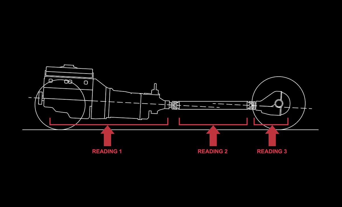
Imagine we are looking at the driveshaft from the driver side of the car with Superman X-ray vision looking at three separate operating components. The first is the engine and transmission angle that we will combine into the first module. The second is the driveshaft itself, and the third is the pinion angle of the rear axle. Generally, the engine/transmission module will be positioned with the output shaft of the transmission lower than the front of the engine by anywhere from 2 to 4 degrees.
If we jump to the rear axle, we will focus on the pinion angle that we will express as having either a nose-up or nose-down angle. In order for the driveshaft U-joints to perform their job properly, they must operate within a narrow set of angles. The key to all of this is to orient the entire driveline with the engine/transmission and rear axle pinion angles roughly parallel to each other.
The TREMEC illustration in their app reveals this relationship, which should help you visualize what needs to happen. What we want to avoid is the engine/transmission and rear axle operating at large intersecting angles. However, this may not always be possible. If the angles intersect, as between the driveshaft and the pinion angle, it’s important that the total operating angle not exceed 3 degrees. If the angle exceeds 3 degrees this will cause a vibration. With all this as our goal, let’s look at how to measure and calculate the operating angles.
Most gearheads know about the TREMEC transmissions company. They manufacture several lines of high-performance five-, six-, and now seven-speed manual transmissions that are found both in OE and aftermarket vehicles. A number of years ago they began dealing with complaints about driveline vibrations that occurred after a new transmission was installed. The installers assumed there was an issue with the transmission when the problem was more often traced to poor driveline operating angles.

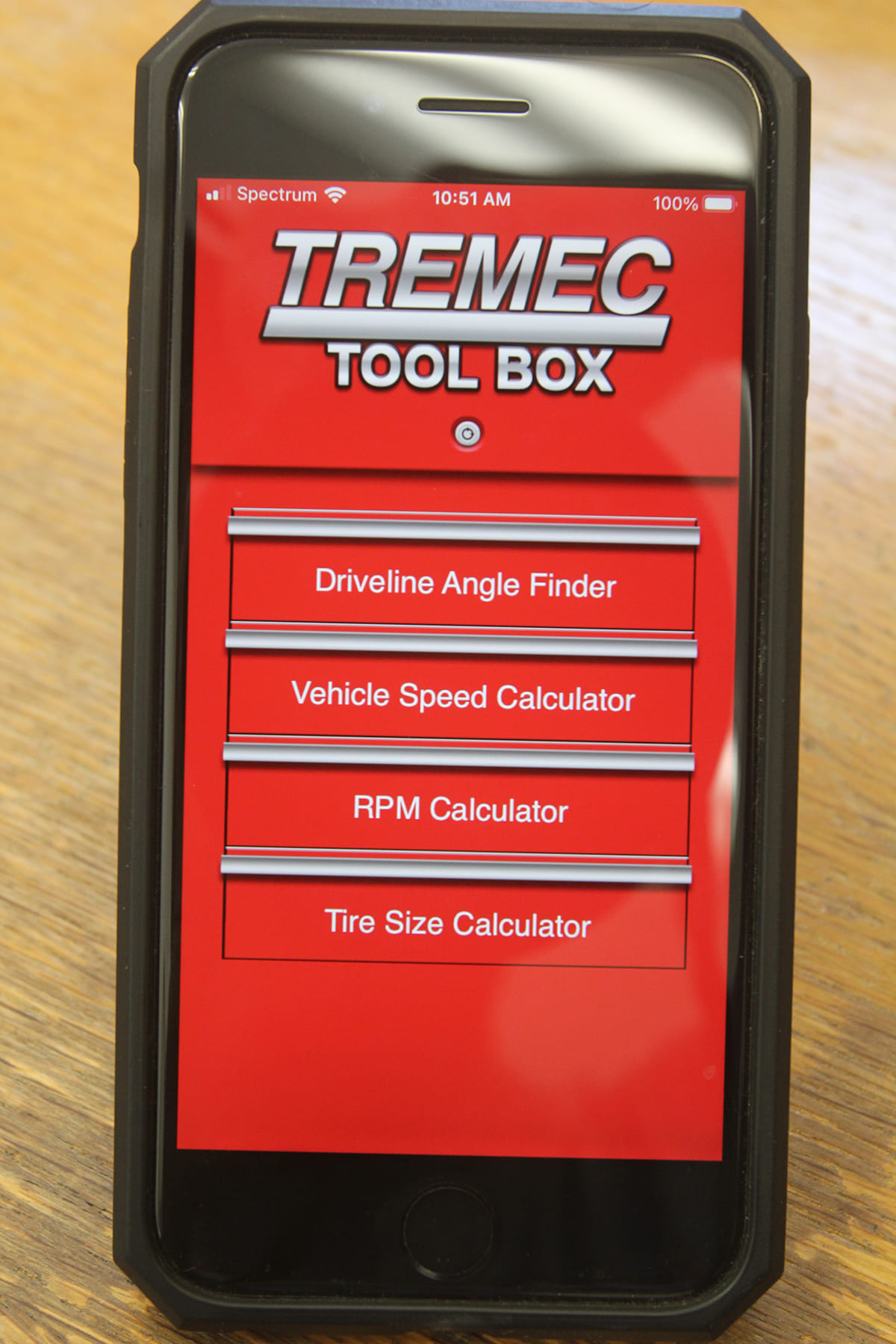
To remedy this situation, TREMEC developed a free driveline operating angle checking application for both Android and iPhones that runs through a simple set of angle measurements and then calculates the entire operating angle in a report. You can find this app by visiting tremec.com, click on Aftermarket, and then click on the TREMEC Toolbox app location.
Before we get into the TREMEC app, it’s important to emphasize the ultimate goal for measuring these angles. Driveline engineers long ago determined that an operating angle at either U-joint of more than 3 degrees is excessive and will cause a vibration. We found this information on spicerparts.com. If the angles are roughly parallel, the rule is to subtract the smaller angle from the larger one.
Let’s say that we then measure the pinion angle of the rearend and discover it is nose down by 1 degree. Keep in mind that the pinion is facing the opposite direction so a pinion down angle will intersect with a driveshaft down angle. Looking at these angles from the driver side of the car, the engine/transmission angle is sloping downward toward the rear. The imaginary line formed by the pinion is also sloping downward, creating intersecting angles. According to Spicer, this intersecting angle is not necessarily bad as long as it does not exceed 3 degrees. However, this intersecting angle is very sensitive to rpm, with the higher the rpm, the greater the potential for vibration.
In the case of intersecting angles, the rule is to add the two angles. With the above driveshaft angle of 1.0 degree and the pinion-down angle of 1.0 degree, this equals 2.0 degrees, which is within the acceptable range. However, if we spin this combination at a high rpm, it may in fact vibrate. This is one reason (there are others) why TREMEC has chosen with this app to push for parallel angles.

TREMEC maintains an ideal driveline angle arrangement to create parallel lines within a total of no more than 2 degrees of operation between the engine/transmission and the pinion. This is most easily accomplished by replicating the tail-down angle of the engine/transmission with a parallel line created by an upward-facing pinion angle. These two angles need to be parallel within 2 degrees. So if the engine/trans is 2.5 degrees tail-down, then the pinion angle at ride height can be anywhere from 0.5 degrees to 3 degrees nose up, which will create a total operating angle of parallel lines within 2 degrees.

Once you’ve loaded the TREMEC free software app into your phone, the next requirement is to measure the angles of the engine/transmission, driveshaft, and rear pinion angle as three separate angles. This must be accomplished with the components at ride height. If you don’t have access to a vehicle hoist, this test can be done on the shop floor with jackstands under the rear axle with the car level. Or, use a drive-on car hoist that will set the car at ride height.
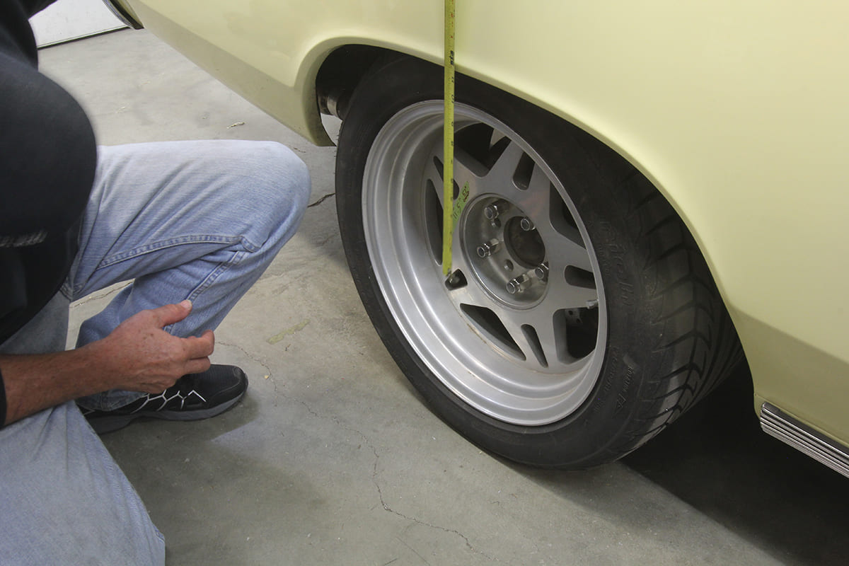
We chose to perform this test using a frame hoist that allows the front and rear suspension to droop. To compensate, we measured the actual ride height from the axle centerline to the top of the rear wheelwell, which was 11½ inches.
Then with the car on the hoist, we disconnected the shocks, removed the rear coil springs, and supported the rear axle with a transmission jack to simulate ride height. With that accomplished, we were ready to measure the angles.
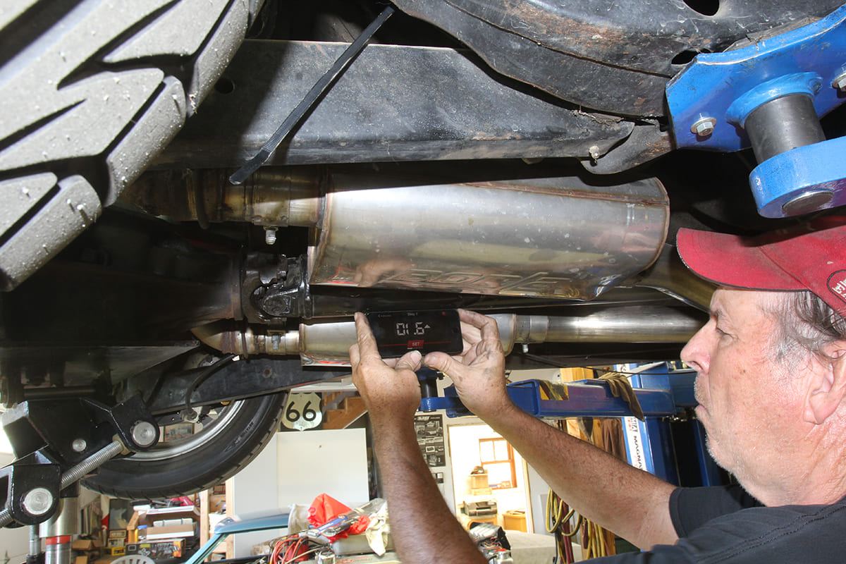
Once you click through the introduction pages on the app, Step 1 measures the angle of the engine and transmission. TREMEC emphasizes that all three measurements should be taken from the same side of the drivetrain. We will take all our measurements with the phone facing out as viewed from the passenger side. The bottom of the engine and/or transmission oil pan is never consistent so it’s best to avoid these. We’ve found that removing the phone from its protective cover will also improve accuracy.
We generally try to find a spot on the machined transmission pan rail. If that’s not possible, laying the phone across three bolt heads on the transmission pan rail will also work. Note that the TREMEC app will deliver an angle number along with an arrow. The arrow points in the direction of the angle. To ensure we are reading the arrow correctly, we often pitch the phone to reinforce that we’re reading it correctly. Moving the phone in the opposite direction from the arrow will reduce the number displayed.
With the engine/trans angle positioned, push the “Set” button on the screen and move to Step 2, driveshaft measurement. We’ve also noticed that often the number that is displayed on the screen is not necessarily the number that is recorded. It can change by two or more tenths of a degree. This may be caused by movement of the phone when touching the screen. If you look at the numbers displayed on our measurements of our test Chevelle, you’ll notice that they don’t agree with the final results but they are within a few tenths of a degree.
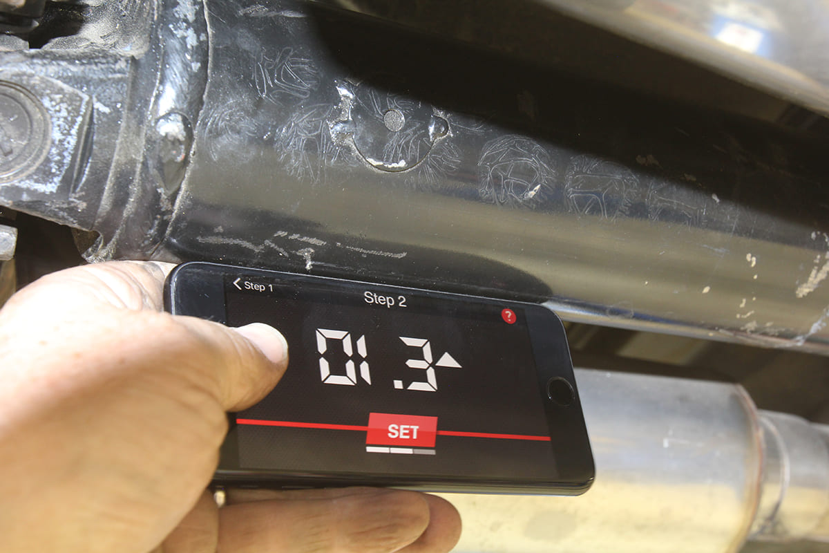
Step 2 is a simple measurement on the angle of the driveshaft taken on the bottom of the driveshaft near the centerline. This number can and will be different from the engine/transmission angle. With the driveshaft angle established, hit the “Set” button again and the screen will transition to the final measurement.
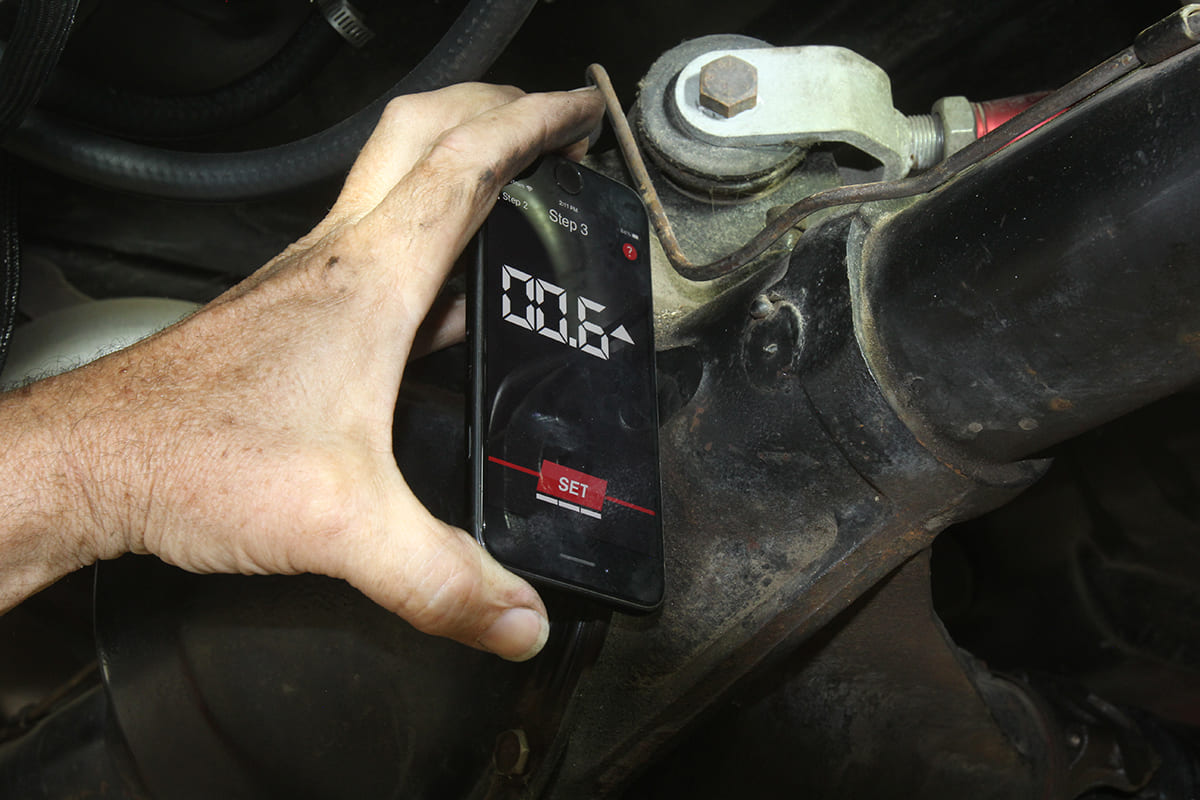
Step 3 is measuring the pinion angle, which can be tricky. For our 12-bolt rearend, we found a small machined pad adjacent to the rear cover that is perpendicular to the pinion. What is important is to make sure the pinion orientation is interpreted correctly as either pinion up or pinion down. If the rear cover area isn’t convenient, laying the phone across three rear cover bolts can be used or you can try measuring off the pinion snout itself but this is often both problematic and inaccurate.

Let’s run through a theoretical set of measurements to illustrate how this app works and what it displays. Let’s place the engine/transmission in a tail-down angle of 3 degrees, a tail-down driveshaft angle of 0.4 degree, and a pinion angle of 0.2 degree nose up. The TREMEC app will deliver an overall failed result because of the intersecting angle at the pinion.
The display will show a green (good) result of 2.6 degrees for Angle 1. This is the operating angle of the front U-joint and is determined by subtracting 0.4 from 3 degrees for 2.6 degrees, which is within the 3-degree maximum operating angle.
Angle 2 is the operating angle of the rear U-joint. Here we have a negative angle of the driveshaft (0.4 degree) and a positive (up) pinion angle (0.2) so we add the two angles together, which creates an angle of 0.6-degree that is again within spec of 3 degrees despite the intersecting angles.
The TREMEC app calculates the overall operating angle as the difference between Angle 1 and Angle 2. In this case the smaller Angle 2 is subtracted from Angle 1 to create 2.0 degrees but because the pinion intersects the driveshaft angle, the TREMEC app will report this as failed. This is because of the intersecting angle of the pinion and the driveshaft. The fix for this situation would be to merely move the pinion up about 1 degree to place it roughly parallel to the driveshaft.
If you look into other driveline angle measurement information, the TREMEC app tends to be very conservative. This is mainly because there are other mitigating factors such as something called a compound angle that also incorporates the driveshaft operating angle as viewed from above the car. This greatly complicates the story, so for the sake of brevity and complex math, TREMEC chooses to push the context of placing the pinion roughly parallel with the driveshaft.
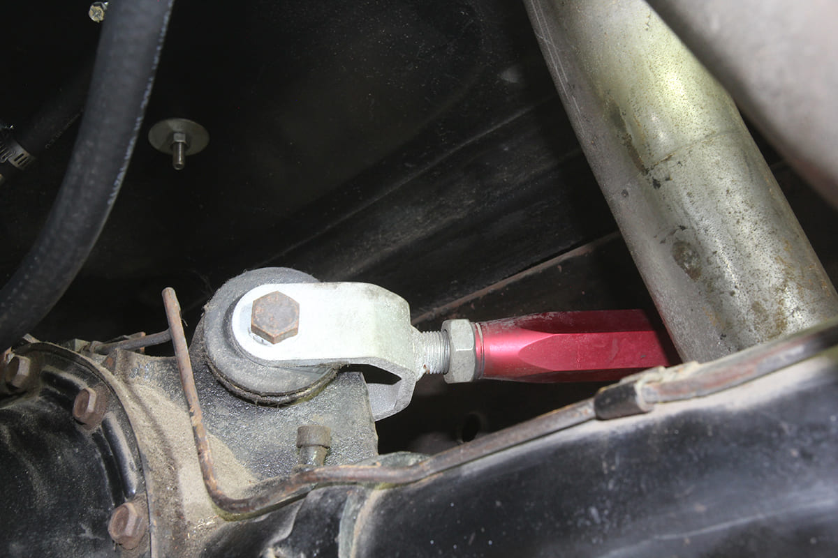
For coil spring cars, the best way to change the pinion angle is with adjustable upper control arms, such as those sold through CPP, Global West, Hotchkis, and many others. Of course, you can also use spacers to change the engine/trans angle to fine-tune the combination. Keep in mind that any change to ride height will affect the driveline angle. If you are in the middle of the driveshaft operating range then you will likely be OK.

This has become a somewhat lengthy explanation but you should be able to see how the total operating driveline angle concept works. A few simple measurements will quickly give you an idea of your car’s operating driveline. You may discover, as we did, that while our car had not previously exhibited driveline vibration, it did measure out of spec. With some minor adjustments, we were able to bring the system into line. Think of this as blueprinting your driveline. It’s not overly complicated and the extra effort will make your driveline happy and will certainly contribute to a longer life on the road.
| Chart 01 |
| Driveshaft Basic Rules |
| 1. The minimum operating angle of each individual U-joint should not be less than 0.5 degree. |
| 2. The operating angles on each end of the driveshaft should be within 1 degree of each other. |
| 3. The total operating angle from the engine to the rear axle should not exceed 3 degrees. |
Source
TREMEC
(248) 859-6500
tremec.com