A Simple Technique for Setting Mechanical Clearance or Hydraulic Lifter Preload
By Jeff Smith – Photography by the Author
With all modern engines either net lash or overhead cam hydraulics, there is an art form that is slowly being lost to history. For older engines with independent stud rocker arms, one of the procedures that was necessary and sometimes done incorrectly was the art of setting valve lash. Engines like a small-block Chevy or Ford with mechanical lifters required a clearance between the rocker arm and the valve tip, which was usually set hot. Hydraulic lifters were less critical but still required a preload. Decades ago, this was done with the engine running and open valve covers, making a huge mess when the engine sprayed oil over the entire engine compartment from 16 tiny lawn sprinklers.

Thankfully, we’ve progressed to a more civilized and far less messy way to accomplish this same task. The valve covers of course still have to be removed, but the engine doesn’t have to run. A sharp engine builder who has been lost to history created this simple procedure that we’ll now pass along for future engine enthusiasts.
The procedure is simple and straightforward. There are other procedures that can be used, but we’ve found that this one is the simplest to remember and does not require you to memorize a firing order or where in the sequence the next step must originate. That can be confusing. This procedure also makes sense from a logic standpoint if you understand how camshafts work.


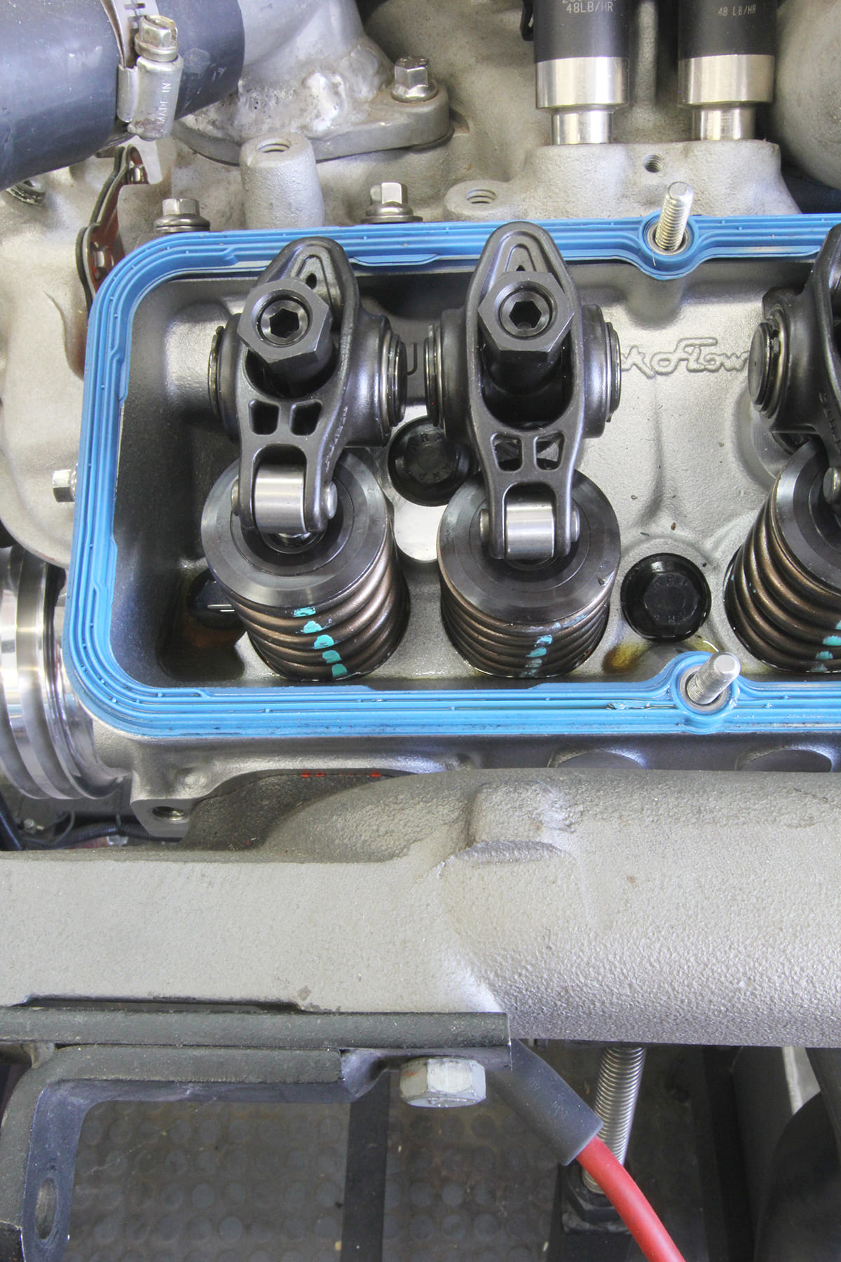
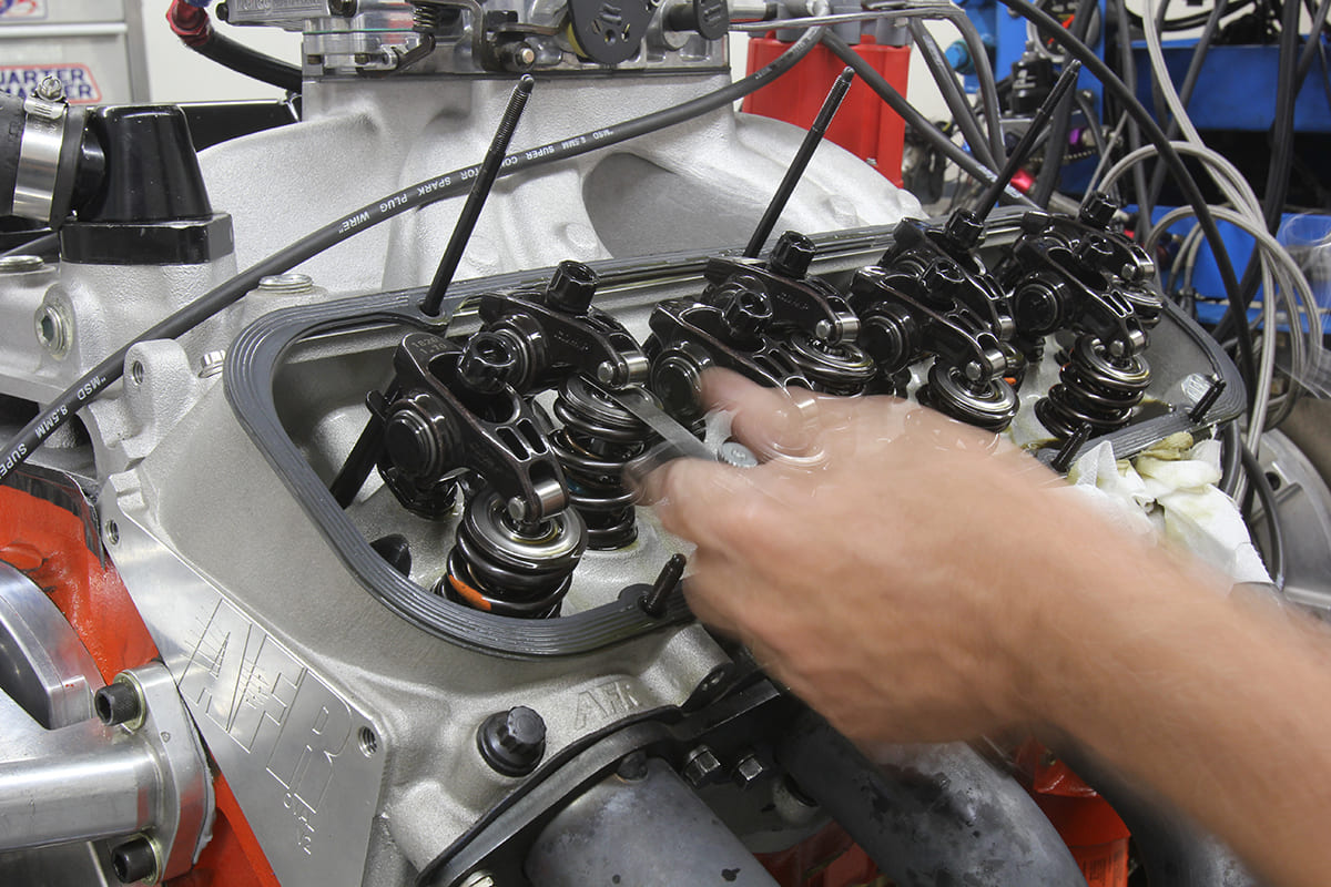
The one rule is to always set lash or lifter preload on a rocker when the lifter is sitting on the base circle of the lobe. The base circle on a cam lobe is the area opposite from the maximum lift point on the lobe. Finding this position for the pair of lifters for a particular cylinder is actually pretty easy. We prefer to set lash or preload by first removing the spark plugs, which allows us to turn the engine over by hand. This is not critical and it can be done with a starter motor if the ignition has been disabled.

Let’s begin the process by explaining that we’re going to set the clearance on each pair of lifters for one cylinder at a time by following the EO/IC (Exhaust Opening/Intake Closing) method. This is how it works.
When turning the engine in a clockwise fashion (looking at it from the front) while watching the movement of the valves on Cylinder One, turn the engine until the exhaust valve begins to open. When this happens, this places the intake lobe for that cylinder on its base circle. This allows us then to set the lash or preload on the intake.
In the case of a mechanical lifter engine, we would then set the lash. We’ll get into more detail on that later. Assuming the engine is up to temperature, we can set the intake lash. If the engine is equipped with hydraulic lifters, we can now set the preload, which is generally between a quarter- and a half-turn from zero lash. Again, we’ll detail how to establish that in a moment.

With lash or preload set on the intake, we can now slowly turn the engine again clockwise until the intake valve is halfway down the closing side. Once the intake valve reaches this point, this places the exhaust lobe on Cylinder One on the base circle. Now we can set lash/preload on the exhaust. With that accomplished, we can then turn the crank again and watch the lifters on the next cylinder in line on the head. We’ve found that setting the lifters sequentially down one head and then the other is simpler to execute. This does require turning the engine over a few more strokes than if you did this by firing order. You can certainly try that and see if it works for you. But we prefer to keep this really simple and just run down one side of the engine and then the other in sequence.

Setting lash with a mechanical lifter engine requires a feeler gauge of the proper thickness–usually between 0.012 and 0.020 inch. With the engine hot, you can set the lash with the adjuster until there is a measurable tug that establishes this clearance. Establishing this is again personal preference. If the engine is cold or is a brand-new engine, the builder will have to compensate for how much the engine will grow or expand after reaching normal operating temperature. We’ve included a chart that was created by Crane Cams to show how much to compensate based on whether the engine is all iron, all aluminum, or an aluminum head and iron-block combination.
As you can see from the chart, an all-iron engine will require a 0.002-inch tighter clearance set cold as the iron components will not expand as much as the steel versions. However, an engine with aluminum heads will expand much more, so the lash will need to be tighter by 0.006 and 0.012 inch if the engine is all aluminum. These are not hard and fast rules but rather suggestions for setting lash on a cold engine. It’s recommended to recheck the lash once the engine achieves normal operating temperature.

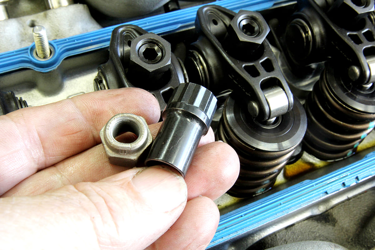
One last point concerning valve lash and perhaps more of a commentary on an automotive myth. A common opinion is that mechanical lash should be checked “constantly” for street engines. That may be true even today if the engine builder uses those lame pinch nuts on a stud. Pinch nuts are notorious for loosening as they are heat cycled and adjusted. These nuts also tend to tear up threads on studs and frankly should be universally not used. Instead, invest in a set of poly locks that use an Allen locking nut to prevent the adjuster from moving. With the lash set with a poly lock, the adjustment will never alter unless something is either wearing or broken. Otherwise, the lash does not change.

Hydraulic lifters were designed so that the owners did not have to check lash. The hydraulic portion of the lifter compensates for expansion in the engine by varying the position of the little piston inside the lifter. A small reservoir of oil constantly adjusts the clearance so that the valves are not held open when the engine is cold.
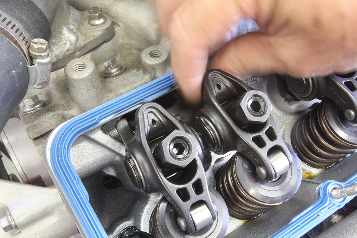
The preload spec is the adjustment once zero lash has been determined. Zero lash is defined where all the clearance has been removed between the lifter, pushrod, rocker arm, and the valve tip with the lifter on the base circle of the lobe. Zero lash is easily found by slowly tightening the poly lock while twirling the pushrod in between your fingers. When zero lash is obtained, the pushrod will be much harder to twirl and all vertical clearance is gone.
Preload varies depending upon who is offering the spec. The most common spec is between a quarter and half turn beyond zero lash. There’s not room in this story to enter the discussion of how preload affects engine operation at high speeds but additional preload (less distance between the hydraulic piston in the lifter and the bottom of the lifter body) has been shown to improve power.
There you have it. While this is not the only way to set lash or preload it is the easiest to remember. Write it down on the inside lid of your toolbox or someplace where it’s easily located in case you forget–but it’s an easy way to set lash as long as you remember EO/IC.
Cold vs. Hot Lash
| Block Material | Head Material | Lash Adjustment |
| Iron | Iron | Add 0.002 inch |
| Iron | Aluminum | Subtract 0.006 inch |
| Aluminum | Aluminum | Subtract 0.012 inch |
Sources
Automotive Racing Products (ARP)
(800) 826-3045
arp-bolts.com
Iskenderian Racing Cams
(310) 217-9232
iskycams.com
Speedway Motors
(800) 979-0122
speedwaymotors.com