

By Gerry Burger – Photography By the Author
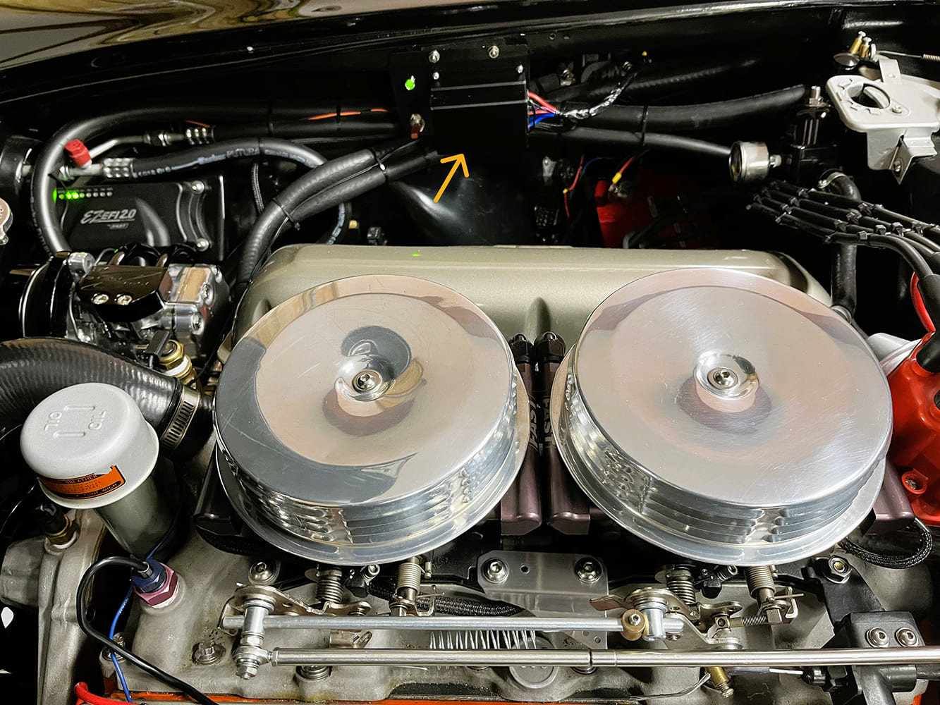
It all started while stuck in traffic. My FAST EFI-fed, 348-powered, 1960 Corvette stumbled and stalled. Don’t panic, turn the key off, then crank it, and the engine starts, though it has a hard time idling and runs rough for several minutes. So, we’ve got a problem. The initial solution is to slip it into Neutral and keep the rpm above 1,000, a poor solution to say the least.
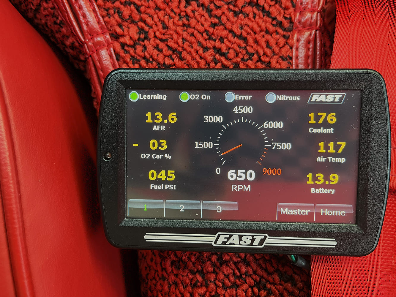
Modern EFI systems are beyond my technical expertise; I recall thinking the push-button telephone was remarkable. Nevertheless, the EFI screen in the cockpit provides a wealth of helpful information. Back home in my driveway, I let the engine idle (650 rpm) in gear until it reaches the 180-degree “fan-on” temperature. The DeWitts fan kicks in, causing the engine to stall, but the screen indicated something significant. When the fan activated, the voltage to the EFI system dropped from 13.9 to 11.6 V. This made the EFI computer very unhappy, resulting in the engine shutting down. It restarted, but the EFI had to undergo a “learning process” to achieve a smooth idle again. So did the driver.
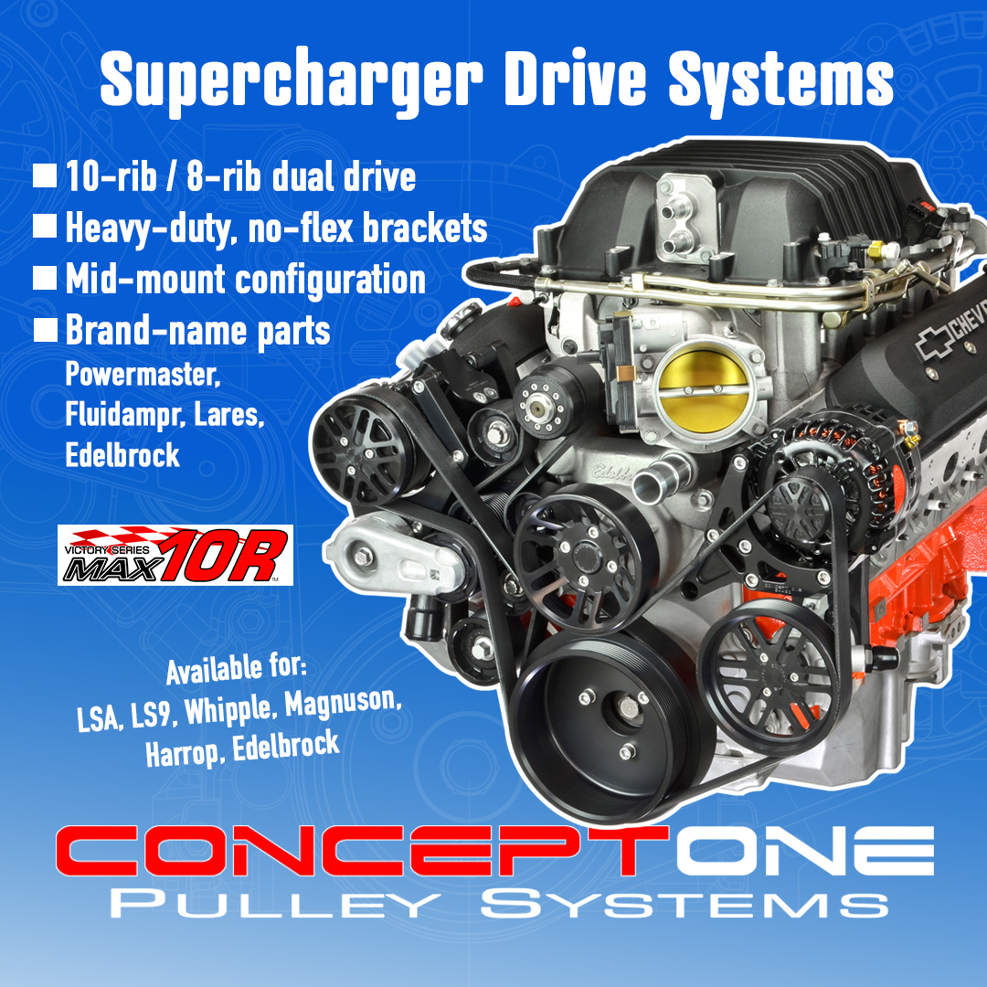
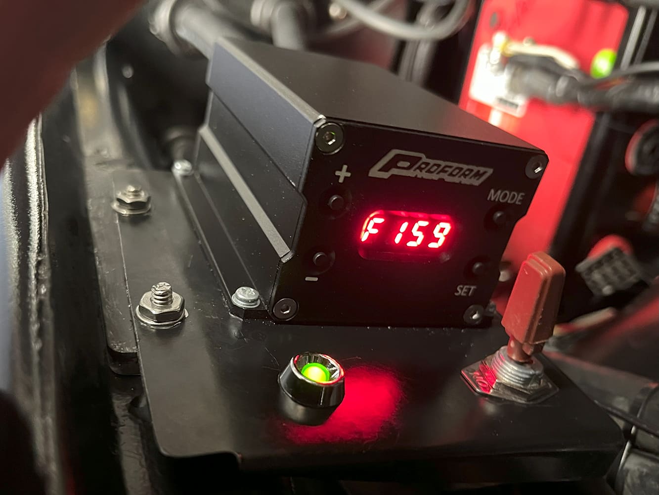
A little research into curing fan-related voltage surges led us to Speedway Motors’ website and the Digital Variable Speed Pulse Width Modulator (PWM) offered by Proform. While Speedway provides other PWM units, we chose the Proform unit because we appreciated the ability to “digitally tune” the engine temperature with just a button press. The installation is relatively straightforward, and this controller enables a “soft start” of 50 percent, preventing the power surge typically caused by a fan relay’s 100 percent start. This PWM eliminates the fan relay, providing a true variable speed fan.

Like many technical problems, there was a possibility of multiple contributing factors leading to our issue. Noticing a significant voltage drop prompted us to consider the battery. As we all know, time flies when you’re having fun, and we suddenly realized our OPTIMA battery was just over 8 years old. We grabbed our battery tester, and sure enough, it indicated “replace.” Interestingly, the battery still cranked the engine, which ran well but could not handle the surge produced by the cooling fan. Our Powermaster alternator managed the surge effortlessly at 1,000 rpm or higher. We promptly installed a new OPTIMA REDTOP. While it’s possible that just changing the battery would have resolved the issue, we’ll never know for sure since we installed the PWM at the same time.
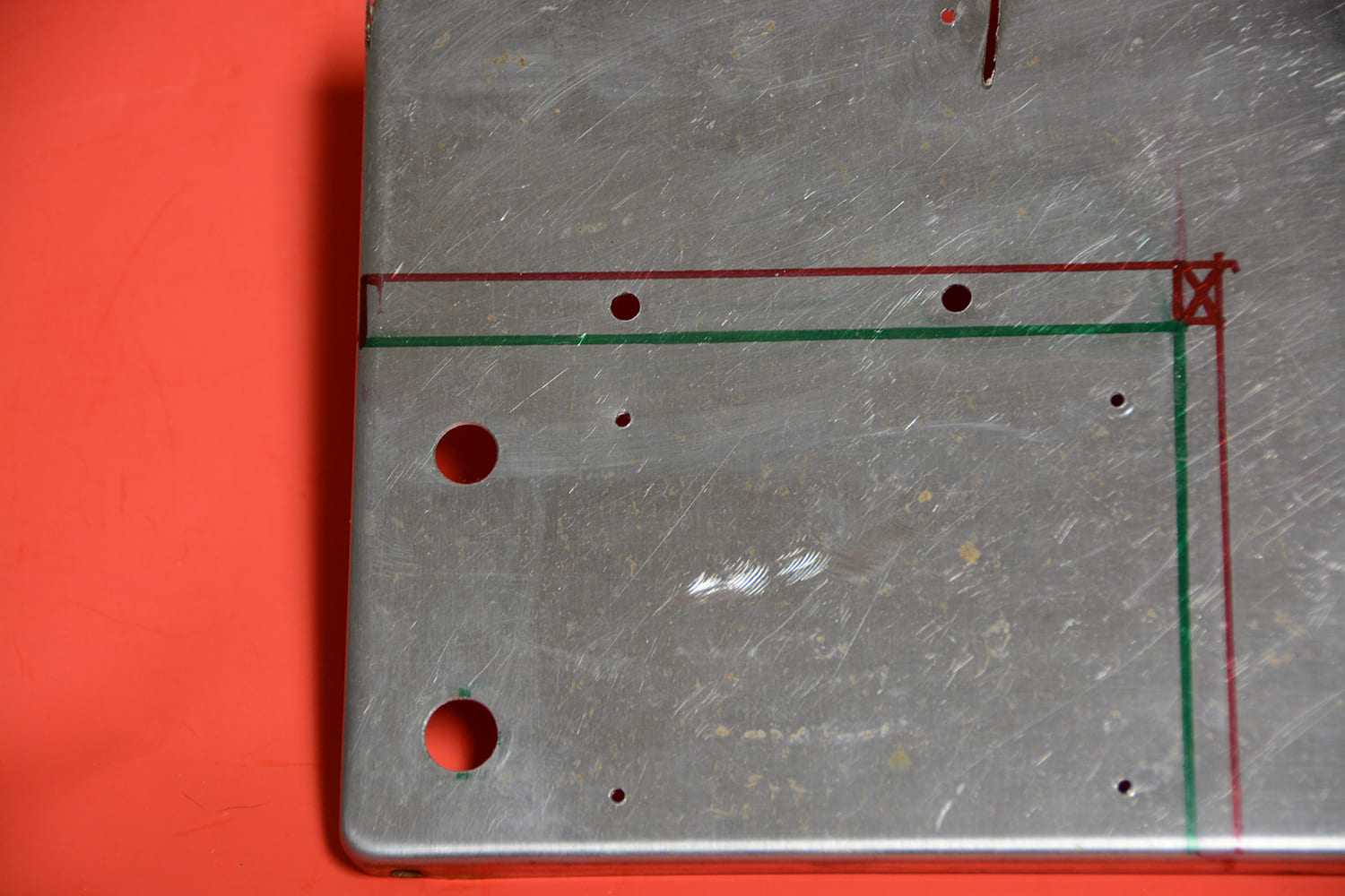
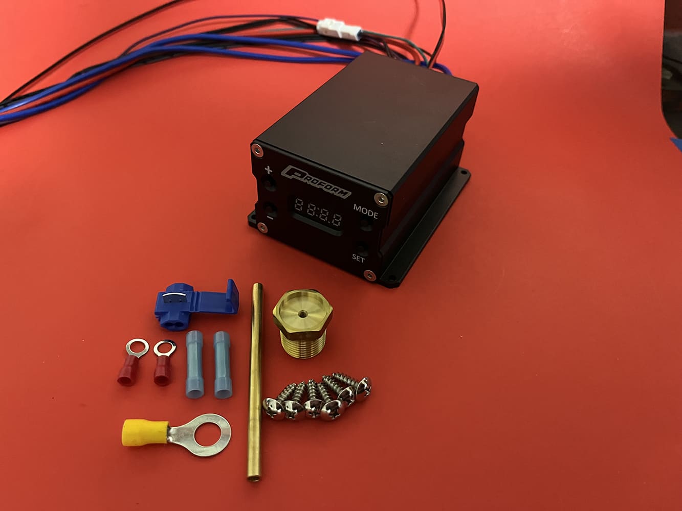
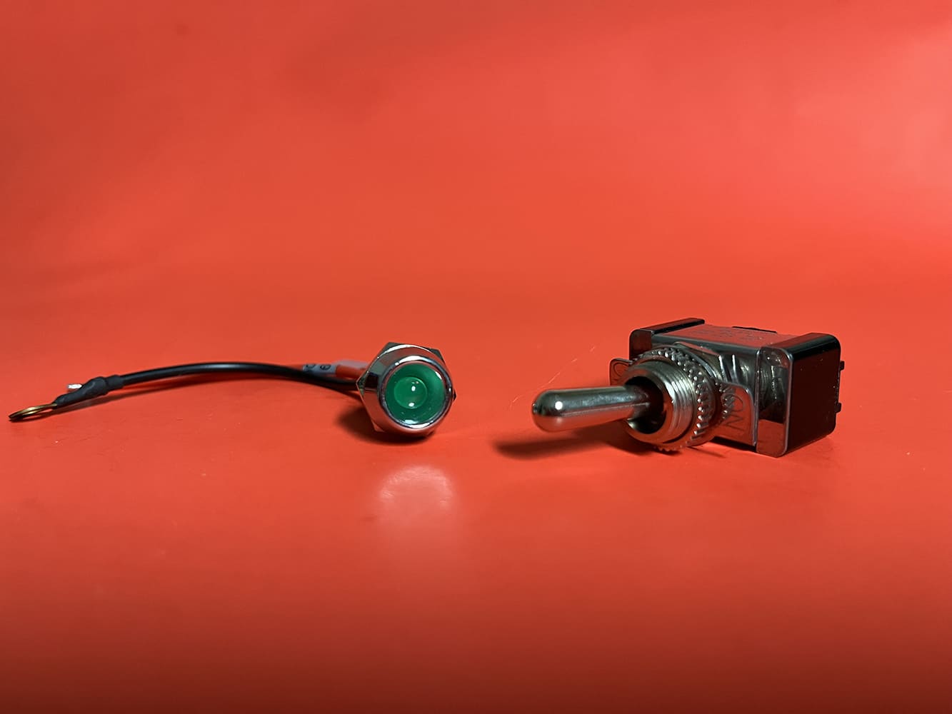
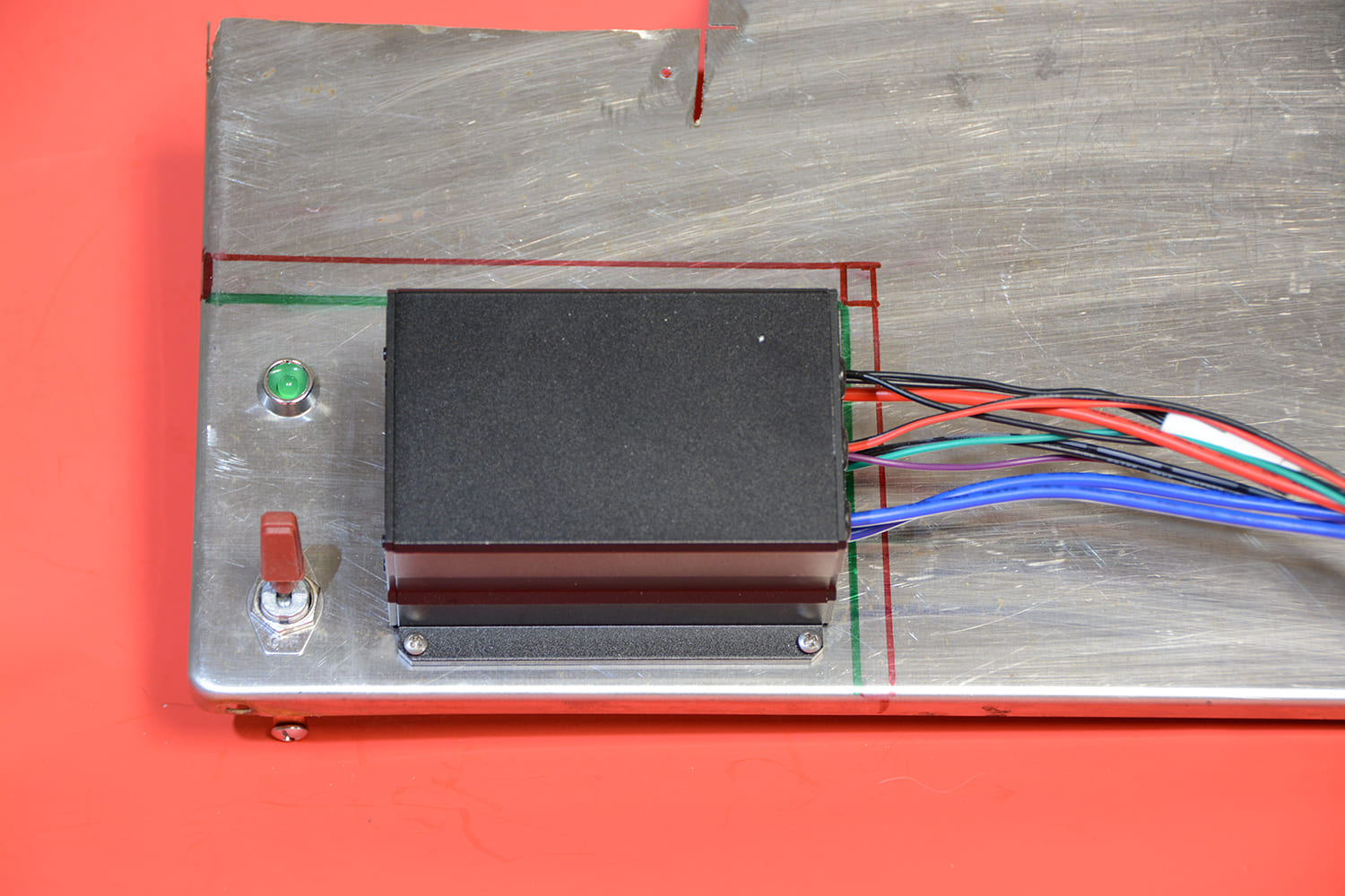
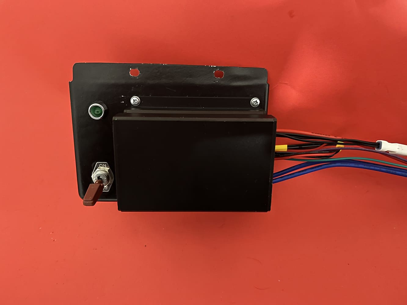
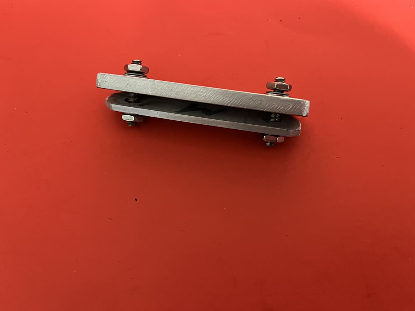
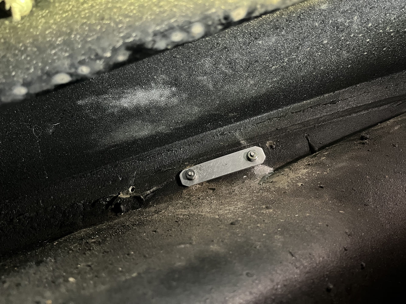
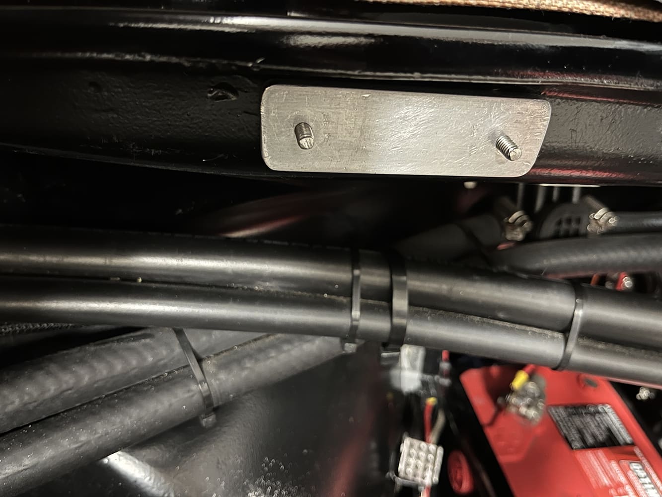
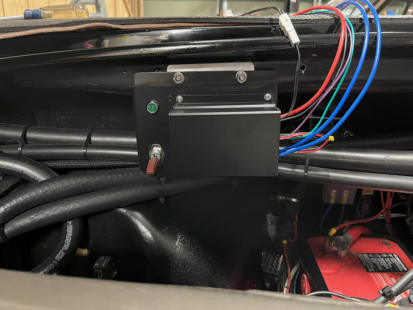
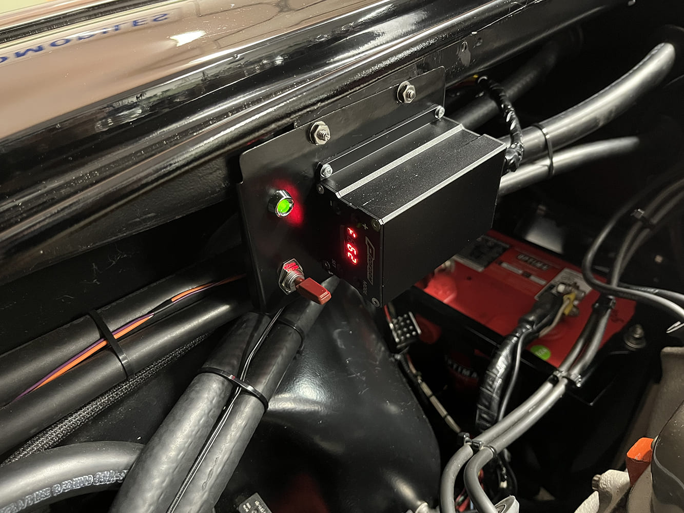
After locating a convenient spot under the hood for wiring, away from excessive engine heat, we constructed a simple mounting plate for the PWM. You might not need a mounting plate if you have a flat area under the hood. Our plate accommodates the module, an LED light, and a toggle switch. The light and switch are not included with the PWM. We found the supplied sheetmetal screws too large for the small mounting holes on the PWM, so we chose smaller M4 screws to attach the unit to our plate. The LED and manual override switch were mounted to the plate and wired to the PWM before securing the plate to a bracket we shaped for the inner fenderwell. We appreciated the idea of having the switch, light, and module all mounted on one removable plate.
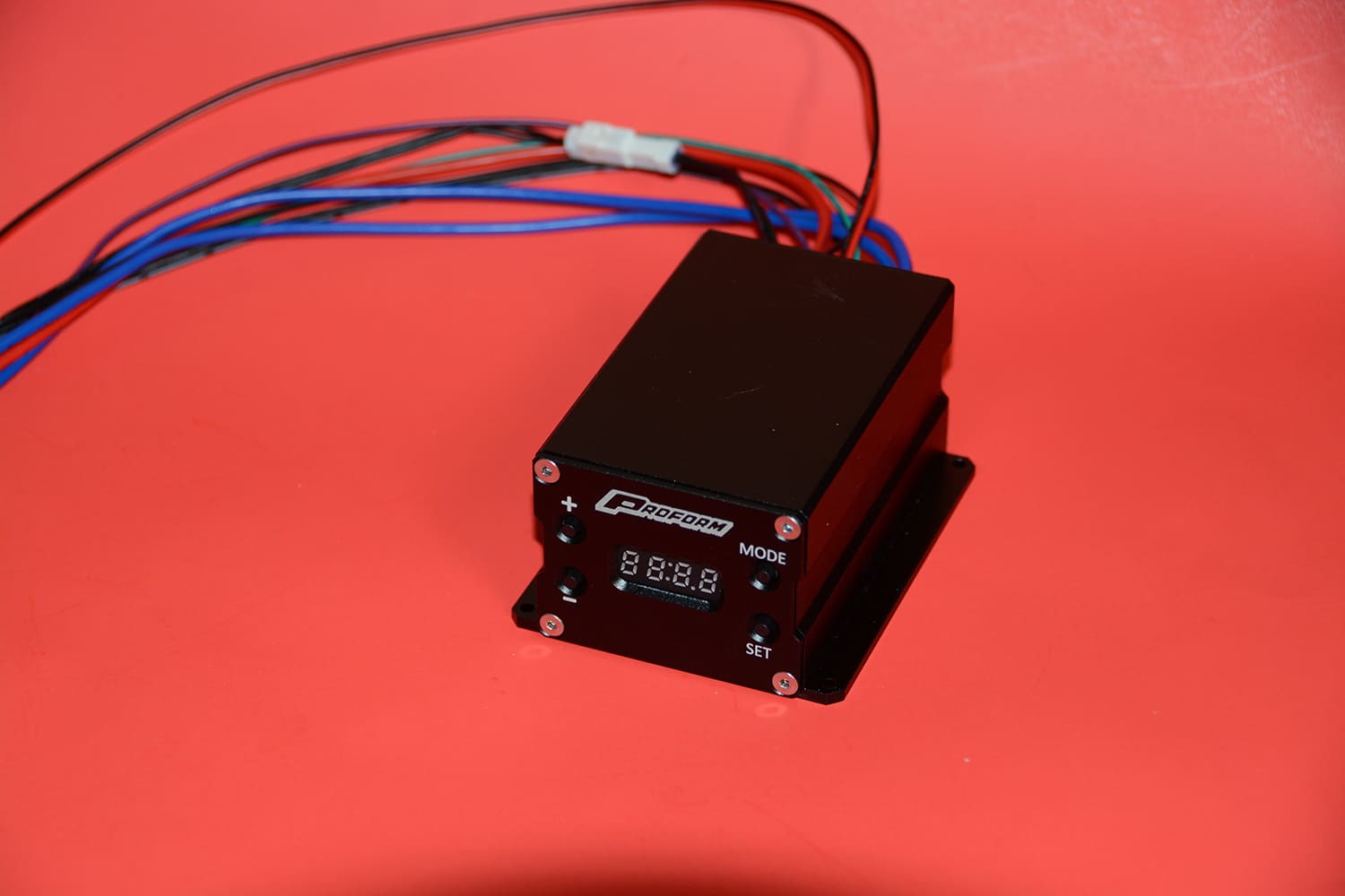
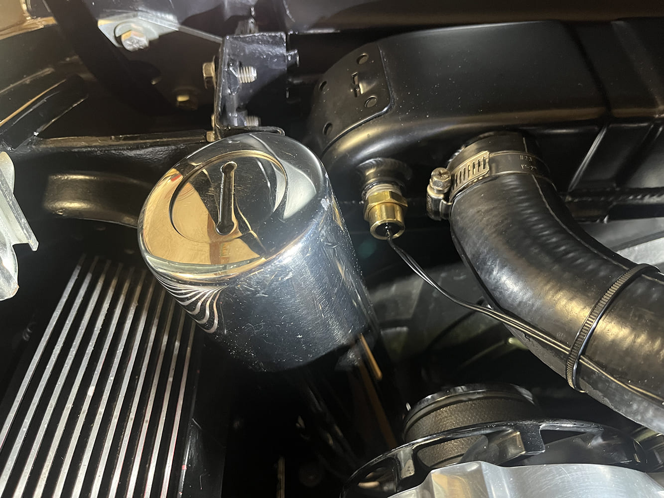
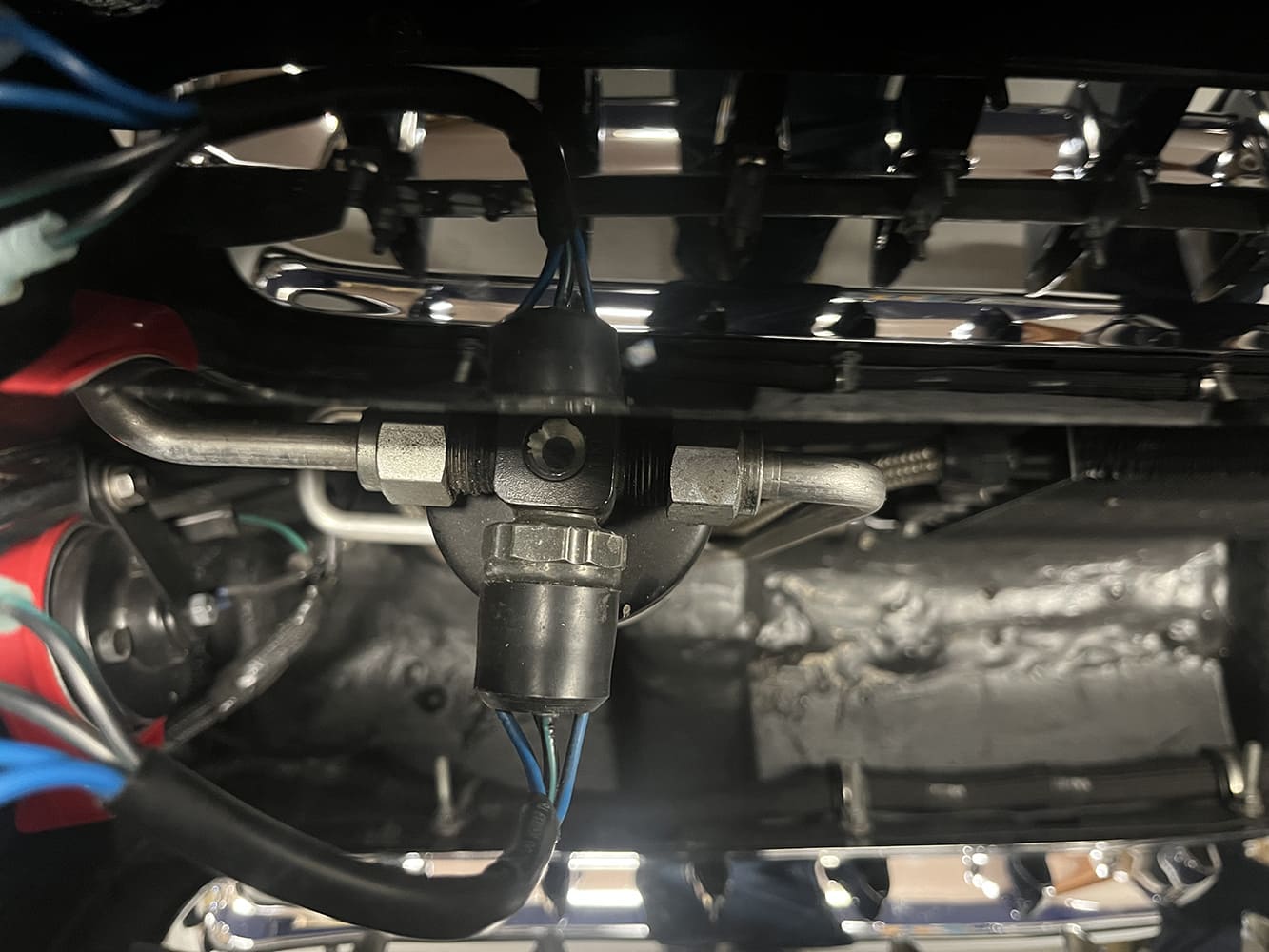
The PWM needs to read engine temperature, and for that, a temperature sensor can be inserted into the coolant via a supplied 3/8-inch NPT bushing or a probe can be inserted in the radiator fins. We opted for the “wet” installation with the sensor in the coolant. The probe in the radiator fins is a “dry” installation in that there is no need to drain coolant.
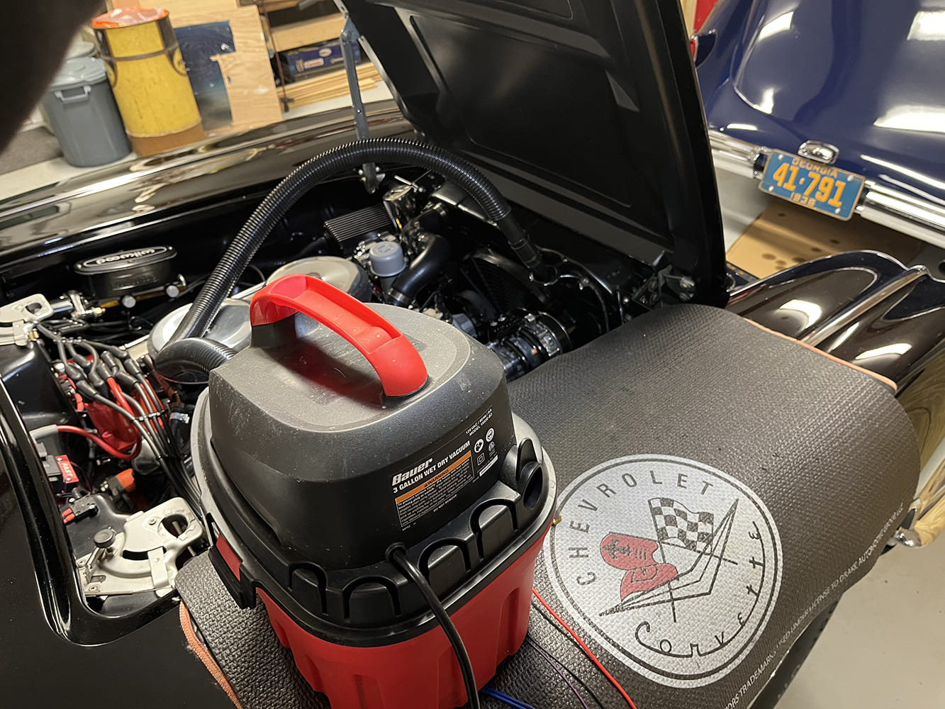
We lowered our coolant level with a small shop vac reserved strictly for “wet work.” With the engine cool, we removed the radiator cap and sucked the coolant out until it was below the temperature sensing port in the upper tank of our DeWitts radiator. We removed the unused temperature sensor from the radiator and installed the 3/8s bushing and new temperature sensor. Following the upper radiator hose, we routed the twin black wire sensor back to the PWM. The length of the sensor wire dictated this route. Since this sensor wire cannot be extended, it is essential to route it before mounting the module. Because our wet shop vac was perfectly clean before use, we could pour the coolant back into the radiator through a simple paint filter and funnel.

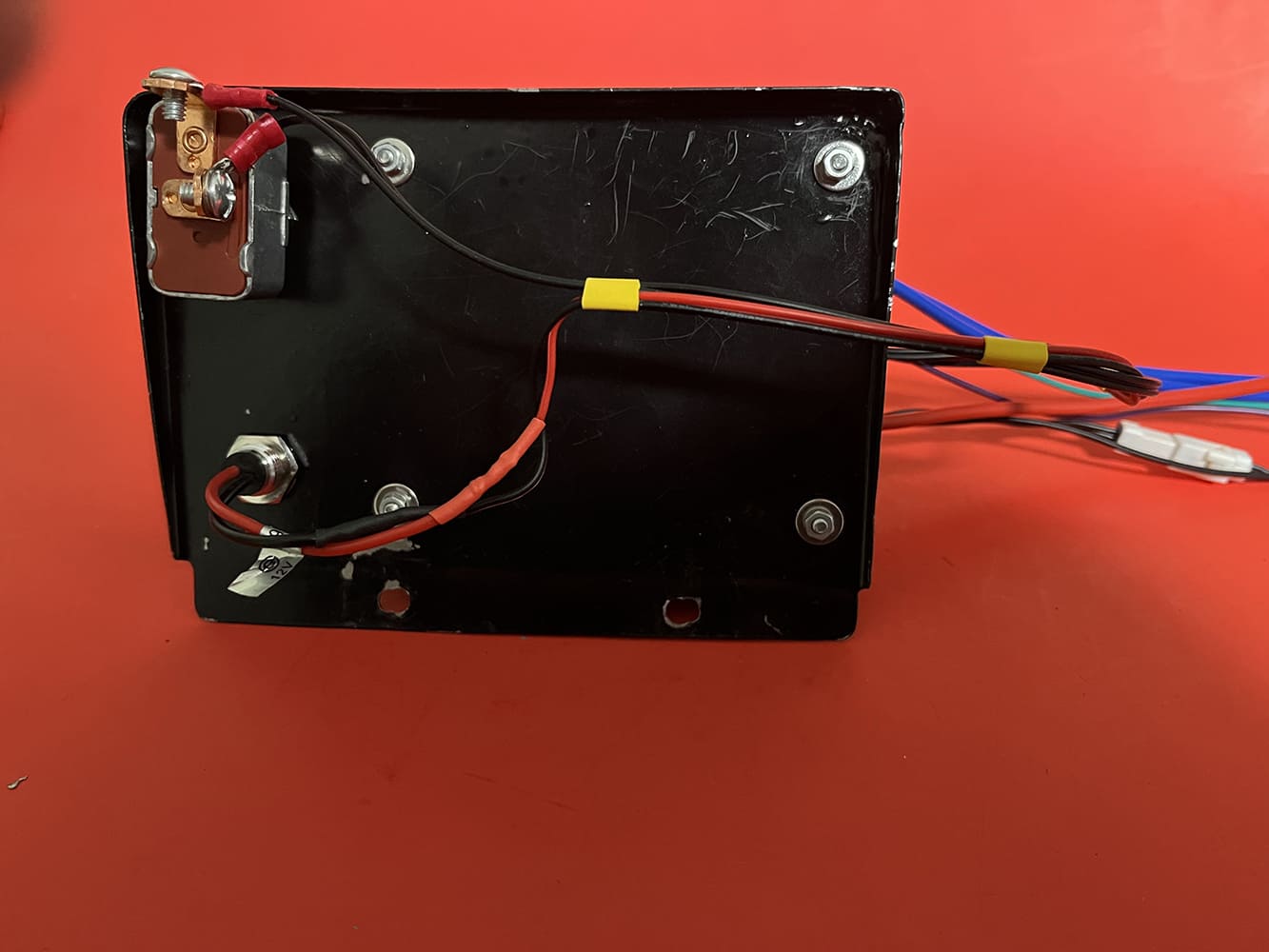
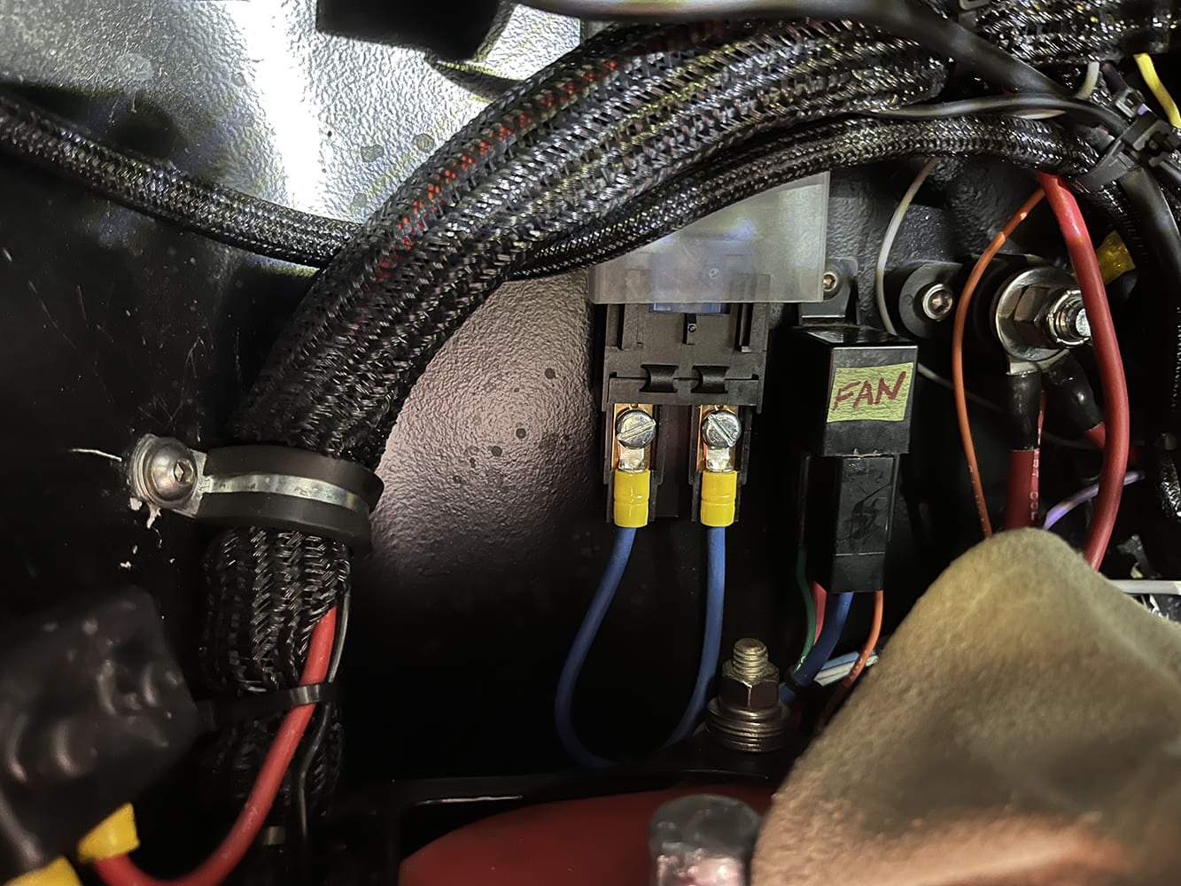
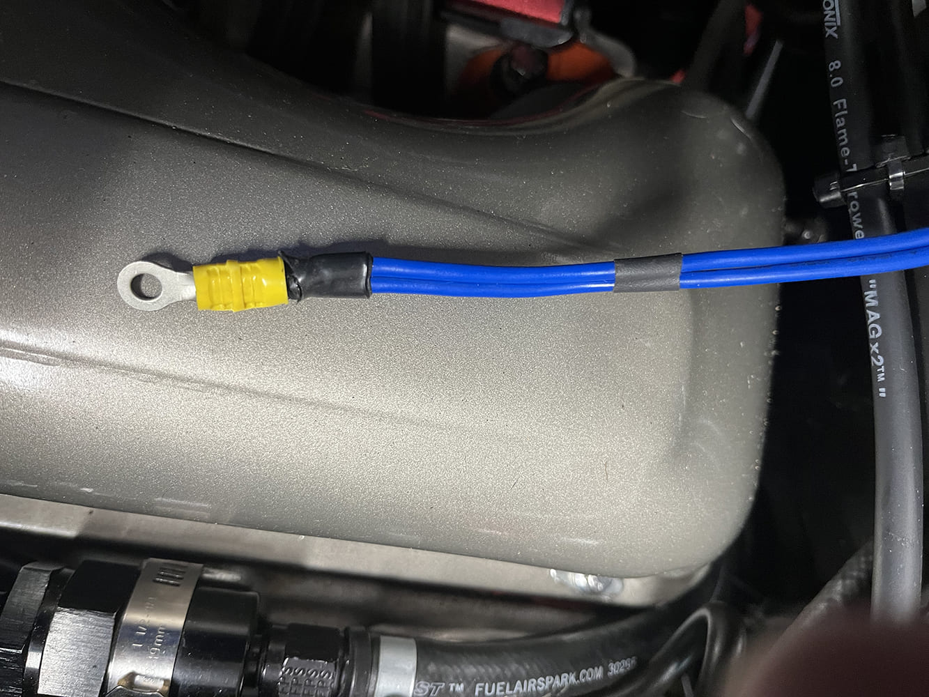
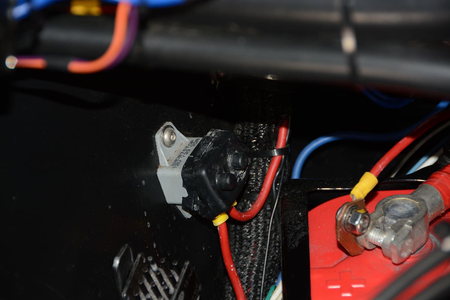
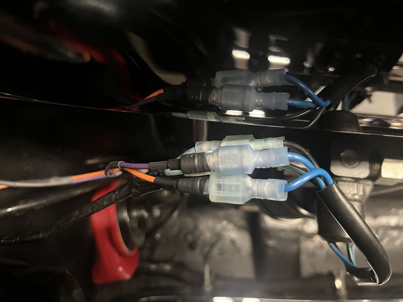
All that remained was the wiring from PWM. First, we wired the switch and the LED light on our mounting plate. Pretty straight forward as per the instructions. Dual red/black wire goes to our red/black LED light, red to red, black to black. The black dual wire goes to the toggle switch. This switch will remain open (off) for variable speed, but should the need arise, a flick of this switch will bypass the module and convert the fan to maximum speed. Most connections required for the new module were readily available thanks to removing the fan relay. The 10-gauge red wire came off the battery and was connected through a 30-amp breaker, located very close to the battery. This PWM can also support twin fans so there are two fan feed wires (blue). Since we have a single fan, we combined these two wires, crimped an end on them, and connected them to a 30-amp fuse to feed the fan. The black single wire is a simple ground wire. The green wire requires an “ignition-on” 12V signal, also available from our old fan relay connection.
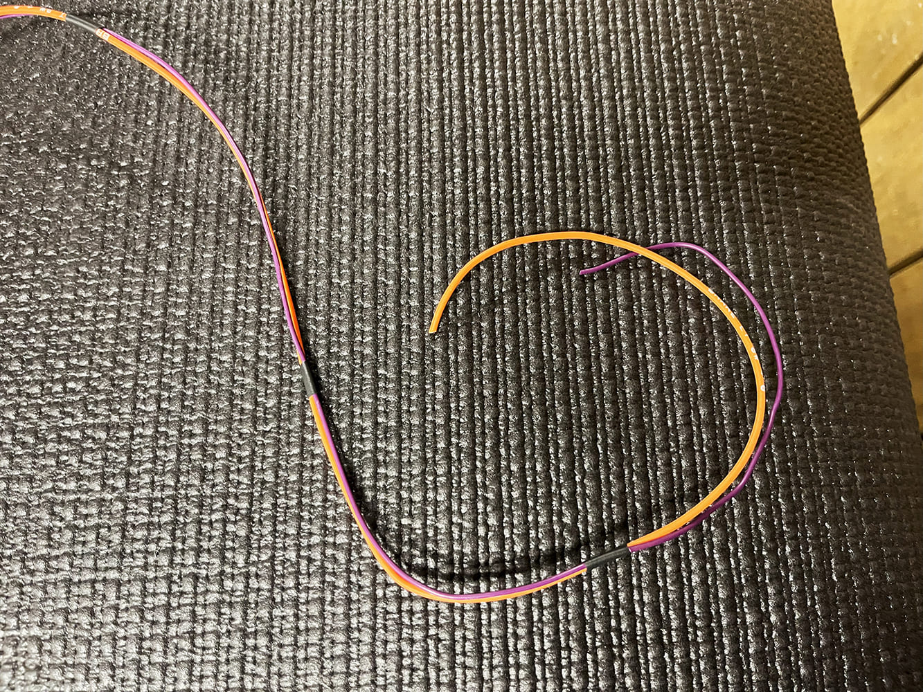
The final purple wire required a 12V signal when the A/C is turned on, resulting in a 100 percent fan operation. I decided to discuss this with my longtime friend at Vintage Air, Rick Love. He pointed out that while a simple “A/C-on” 12V signal would activate the fan, it would remain on for the entire duration of A/C usage, even if traveling at 70 mph on the highway when generally no fan is needed. He proposed a better solution: using the trinary switch already in our Vintage Air system to control the cooling fan. This would send a full-fan signal to our new module when the trinary switch reaches the preset 254 psi; there would be no fan speed adjustment below that pressure. One minor issue: the trinary switch with the fan relay was interrupting a ground, which meant we needed to send a low-amperage, 12V signal to the module. Therefore, we eliminated the ground going into the trinary switch and removed the ground wire previously connected to the fan relay.
Remember that green 12V, low-amp wire, the ignition-on feed to the module? We used that same wire to power the trinary switch. A simple “one-in, two-out” solder splice provided a reliable connection. We routed the new 12V feed wire to one side of the trinary switch. The purple wire from the module connected to the other side of the trinary switch, completing our A/C “call for full fan circuit,” which works perfectly.
We reconnected the battery cables to our new OPTIMA and turned on the ignition switch. The green LED glowed steadily, indicating a good sign, since a blinking LED signals a problem such as a short circuit or an overload. We started our faithful 348 W-motor, and the module display showed the coolant temperature. We decided to set the temperature based on engine temperature rather than radiator temperature. We aimed for 180 degrees, and our DeWitts radiator was up to the task. Setting the fan-on temperature was done by pressing the set button, followed by the + or – buttons on the module and then a quick touch of the “set” button. The fan begins at 50 percent, 6 degrees before reaching the desired run temperature, and the fan speed adjusts as needed to maintain the target temperature. We monitored our Classic Instruments temperature gauge in the cockpit and adjusted the fan-on temperature until we reached the desired running temperature. You can also scroll through the module screen to check the fan’s amp draw and the current coolant temperature. If left untouched, the digital screen shuts off.

While observing our FAST EFI screen, we noticed the temperature rising and the fan activated 6 degrees early. The voltage displayed on our screen showed a drop from 14.1 to 13.9, with no change in engine speed, and we could barely hear the cooling fan running. The temperature appeared to remain closer to our target since the fan adjusted its speed to maintain a cool environment, unlike the previous “fan-on, fan-off cycle” we experienced with the fan relay. In our situation, we set the radiator tank coolant approximately 8 degrees below our desired engine temperature. To date, we are very pleased with the performance of the Proform Module as well as our EFI.
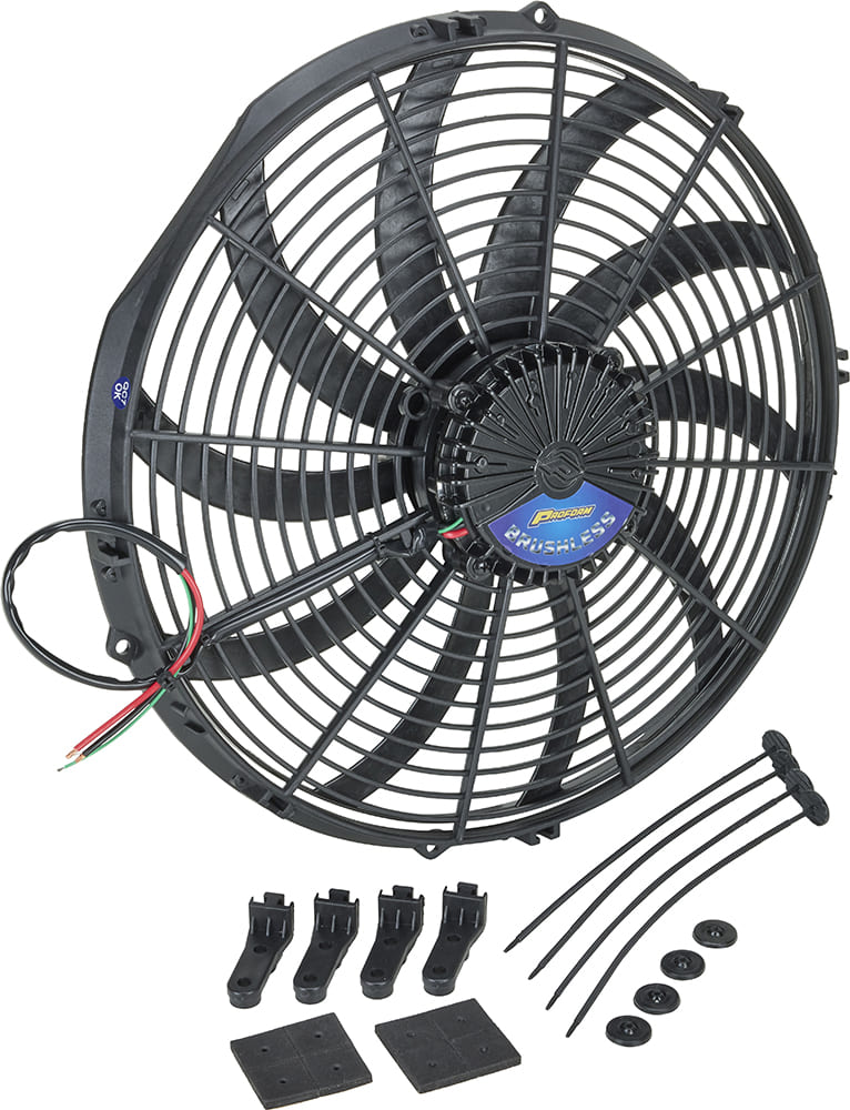
OF COURSE THERE IS ALWAYS THE BRUSHLESS OPTION
In simple terms, electric motors convert electric current into rotational motion. Both brushed and brushless motors achieve the same result, with the main difference being how they control the power: the mechanical transfer of power (brushes) versus solid-state electronic transfer of power (brushless).
In a brushed motor, the stator (the stationary part) contains permanent magnets, while the rotor (the moving part) has electromagnets. Carbon brushes in contact with the commutator in the rotor transfer electric voltage to it, creating an electromagnetic field in the rotor. The continuous flipping of the magnetic pull’s polarity, via the commutator, gets things spinning.
In brushless motors, things are reversed. Now the rotor contains the permanent magnets, and the stator creates the electromagnetic field. Instead of brushes, an electronic controller creates a variable current that powers the motor coils in succession. This forms a rotating magnetic field in the stator powering the rotor magnets, creating the spinning motion.
A quick look at the Speedway website introduced us to the world of brushless fans. Ultimately, it was sheer laziness that led us to the PWM module. Our DeWitts radiator and fan combination works well, but switching to brushless in our C1 Corvette would have required removing the hood, draining all the coolant, disconnecting the transmission cooler, and taking out the radiator because the existing fan is riveted to the aluminum shroud built into the radiator. However, brushless remains a viable option.
When all this surge/EFI trouble began, we should have first checked our 8-1/2-year-old battery, so remember that when troubleshooting low voltage under high demand. However, if your battery is in excellent condition, cooling fans still create a significant draw, and EFI does not like voltage or amperage variations. We discovered brushless cooling fans while exploring ways to eliminate the fan-on surge. These fans remove the traditional fan relay and start at 50 percent, which means less surge; additionally, most brushless temperature sensors incorporate a PWM signal, allowing the fan to operate at variable speeds to maintain the desired temperature and eliminate the on/off cycle. Brushless fans run cooler and quieter, generally have a long lifespan, are lighter, and are thinner. It’s a pretty cool deal. MR
Check out this story in our digital edition here.

SOURCES
DeWitts
(517) 548-0600
dewitts.com
FAST
(800) 999-0853
fuelairspark.com
OPTIMA BATTERIES
(888) 867-8462
optimabatteries.com
Proform Parts
proformparts.com
Speedway Motors
(800) 979-0122
speedwaymotors.com
Vintage Air
(800) 862-6658
vintageair.com