By Jeff Smith – Photography by the Author
When it comes to assembling your next engine, the process of setting bearing clearances can be a bit intimidating to aspiring engine builders. Worse yet are the ones who just assume that if the crankshaft spins with the main caps torqued the clearance must be correct. If you are reading this story, you are likely the type of engine enthusiast who knows that effort usually is handsomely rewarded.
This process does require some specialty measurement tools and a fair amount of patience, but it is neither difficult nor mathematically challenging. It just requires the willingness to perform some careful measurements while paying attention to the details. There are also some tweaks to the process that can be employed to come up with the proper specifications.
Let’s start with the actual specs you should be shooting to achieve. We will use a normally aspirated 6.2L LS engine as our example. Main and rod bearing clearances typically fall in around 0.0025 inch for a reason. Many years ago, Callies published a crankshaft catalog with three graphs that compared bearing clearance to load capacity, bearing temperature, and volume of oil passing through the bearing. We’ll skip the details to reveal that roughly around 0.0025 inch was the clearance that optimized all three of those categories. The example was a small-block Chevy crankshaft.
Inspecting an Engine of Questionable Origin: Learning the History, Cubic Inches, and Compression Ratio of a Used LS Engine
The more generalized rule of thumb for proper rod and main bearing clearances has been the classic 0.001 inch for every 1 inch of journal diameter. All modern LS engines use a 2.559-inch main journal diameter and share their rod journal diameter with the large journal small-block Chevy at 2.100 inch. Another point worth making is an old drag racing cliché that contends that if the clearances in your engine are a little loose, only you know that. But if you build the engine with clearances too tight, everyone will know when the engine fails.
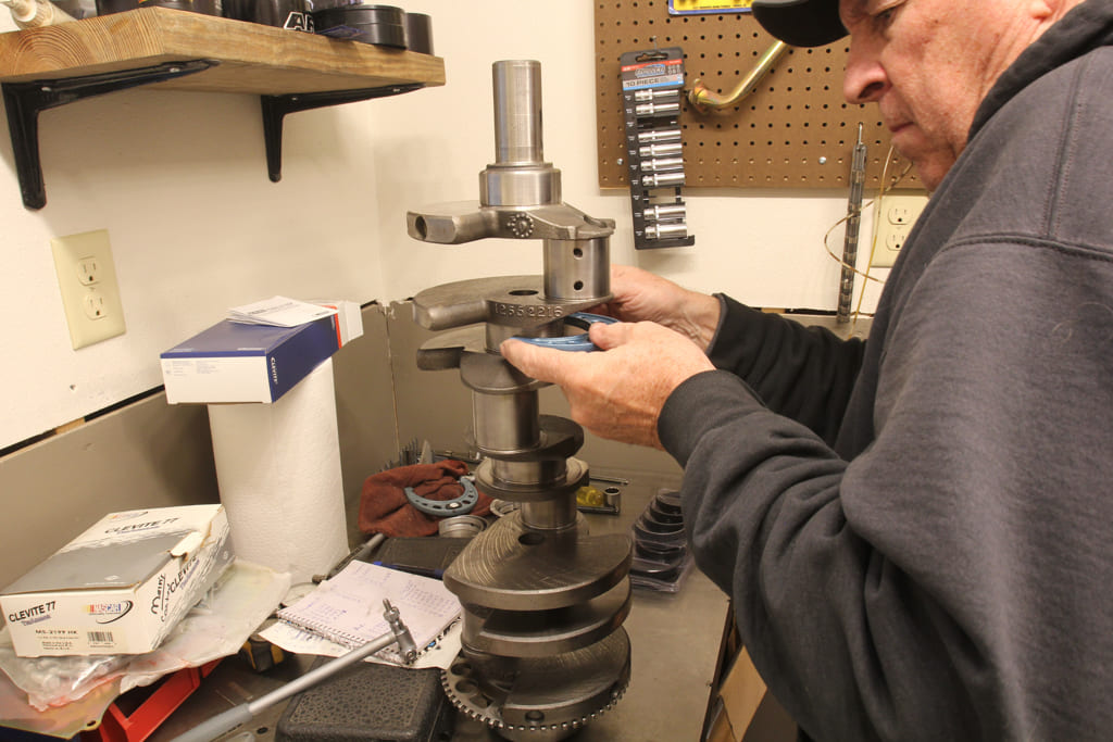
So, with those thoughts in mind, we chose to shoot for the acceptable 0.0025-inch spec for both the connecting rod and main bearing clearances. For this story, we’ll focus on the main bearing clearances and the steps we used to achieve our goal.
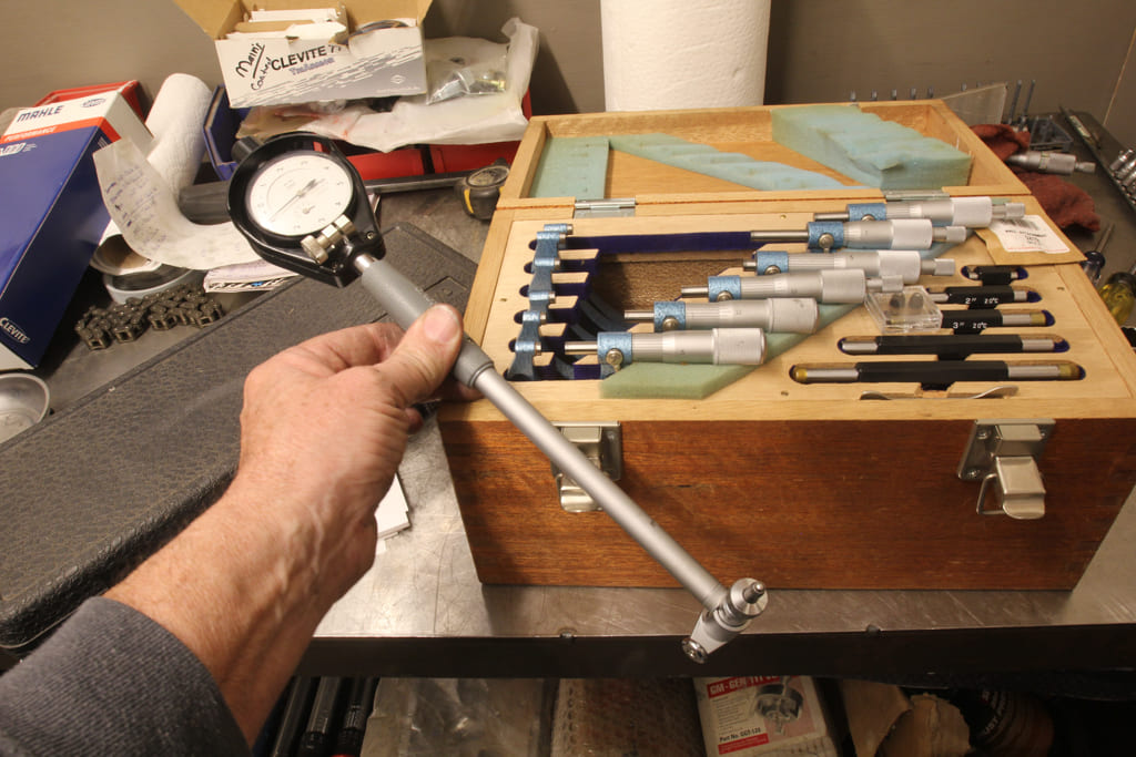
Before we get into measuring devices, it’s worth mentioning that if you really care about doing this job correctly, Plastigage will never enter your mind. You will never find Plastigage in a professional engine builder’s toolbox except as an example of what not to use. If you don’t own a set of micrometers or a dial bore gauge find someone who will loan you the tools or do the measurements for you.
To begin we used a set of quality micrometers that will measure out to 0.0001 inch, which is the first step in the process. Using a budget micrometer that only measures to 0.001 inch will not produce the accuracy needed for this process. The first step was to use a quality standard to ensure the micrometer will be accurate for the shop’s ambient temperature. Once we measured all the main and rod journals, we zero’d our dial bore gauge based on the main journal diameter for Number One main, which was 2.5590 inch. We then kept track of the different main journal sizes to establish our clearances. The largest journal measured 2.5590 inch while the smallest measured 2.5587 inch.
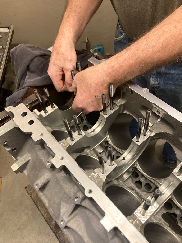
By establishing zero as the crank main journal diameter of 2.5590 inch on the dial bore gauge, the actual inside diameter of the main bearing housing with the bearing torqued in place will indicate the actual bearing clearance. It’s important that this always be measured at the true vertical of the bearing. This is because all bearings are designed with an eccentricity near the horizontal portion to prevent the bearing from potentially pinching in when compressed in place. As a result, the clearance at the horizontal will be substantially larger compared to the diameter measured at the true vertical. The true vertical distance is the proper bearing clearance.
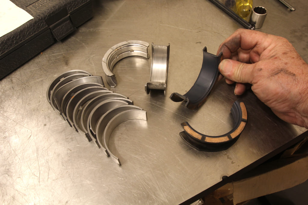
We chose to use a set of Mahle Clevite coated tri-metal main and rod bearings for this engine. There are other companies to choose from such as ACL, Speed-Pro, and King Bearings, to name a few. We chose the Mahle Clevite tri-metal bearings because they are better bearings for performance applications where higher loads are anticipated.
Lube Talk: Ten Useful Facts About Engine Oil
In the past, we tried a set of OEM-style bi-metal bearings in a big-block Chevy only to discover these harder aluminum bearings peel when the crankshaft deflected under the load from a supercharger. When the harder aluminum main bearing material peeled like an onion, this debris instantly killed the adjacent rod bearings. Tri-metal bearings are softer than the bi-metal aluminum versions and for performance applications they’re the only real choice.
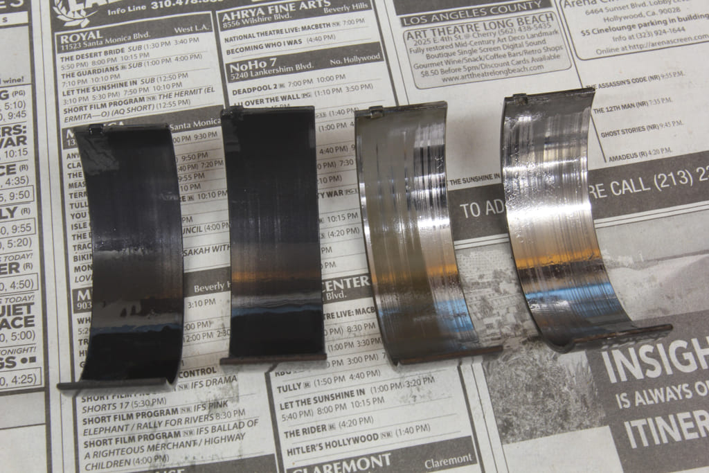
We also opted for the more expensive, coated versions of the Mahle Clevite bearings because of their added durability. Several years ago, we reported on a test of coated bearings and synthetic oil performed by our friend Lake Speed Jr. in which a 383ci small-block was abused at 1,500 rpm at high load for 2½ hours. The result of the test revealed that the best combination to minimize bearing wear was to use synthetic oil with coated main and rod bearings. We’ve included a small chart to show the results of used oil testing from SPEEDiagnostix. The results revealed to us that coated bearings are worth the investment, especially when paired with synthetic oil.
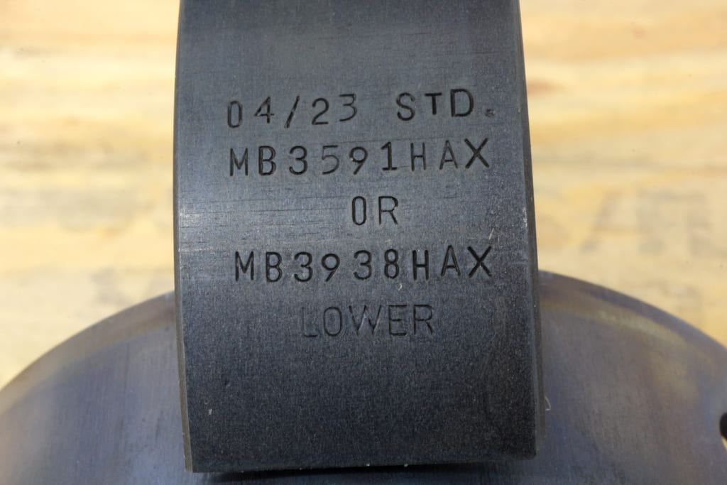
The first set of standard Mahle Clevite bearings we installed produced slightly tight clearance figures ranging from 0.0017 through 0.0023 inch. After measuring twice, we determined that the best course would be to step up to a 0.001-inch-wider clearance bearing. Most bearing companies identify these bearings as 1X versions. If we had needed to tighten the clearance, these are usually indicated in the part number suffix as -1.
Adding a full pair of these bearings would push some of the main sets well beyond our desired 0.0025-inch goal, but as long as you stay with the same bearing company you can mix different half shells together to come up with the desired clearance. For example, using a standard half shell with a 1X half shell should theoretically increase the overall clearance by 0.0005 inch.
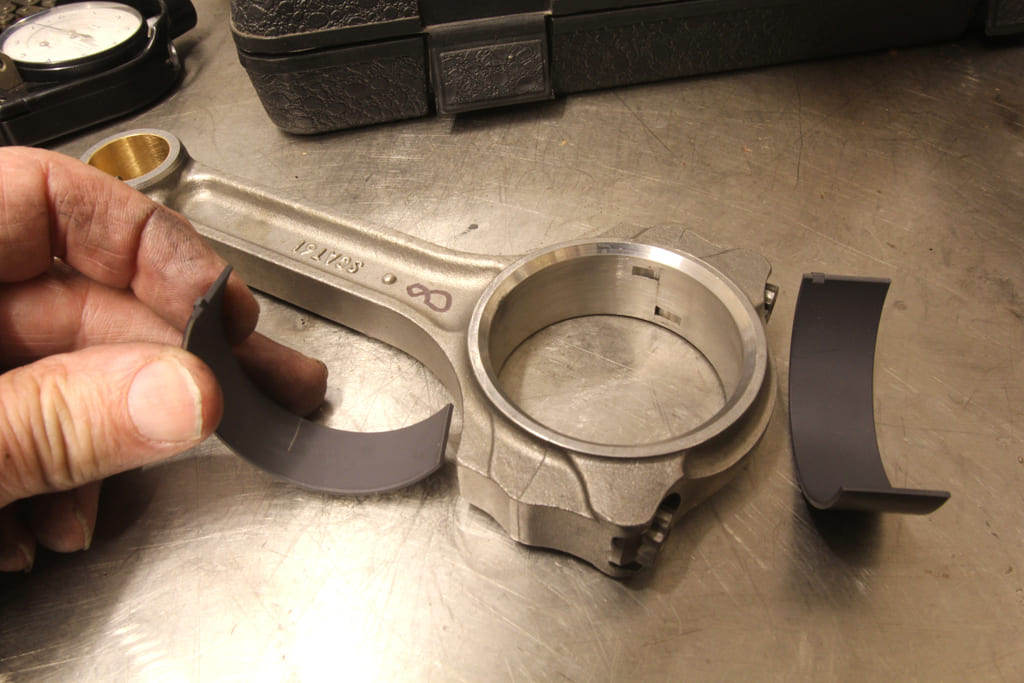
With our engine, the Number One and Five mains were very close to our 0.0025-inch goal using standard bearings but the center three mains, including the thrust bearing in Number Three were too tight. Number Three required the full use of both 1X half shells. With numbers Two and Four, we combined a 1X half shell with a standard bearing shell.
As often happens, the change to a larger clearance half shell increased the clearance slightly more than 0.0005 inch. In other cases, we’ve seen where the addition of a larger half shell adds only perhaps 0.0003 inch. It’s not a consistent change, which is why you always need to measure the clearance again rather than just assume the change results in the clearance you anticipate.
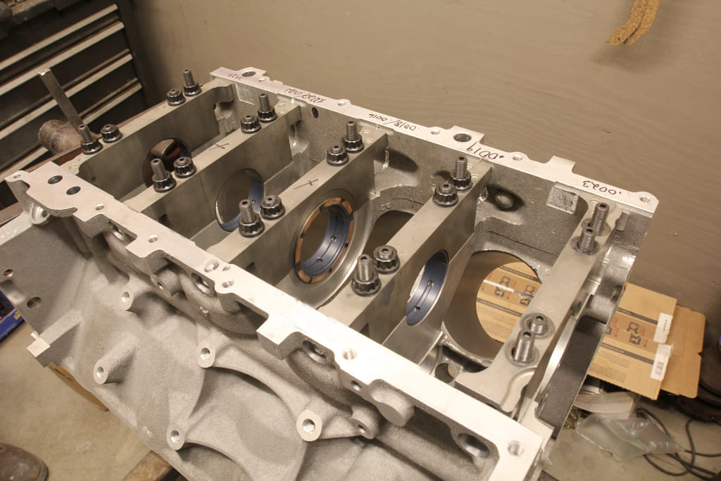
This same procedure with larger or smaller half shells can also be applied to rod bearing. Occasionally when we have a situation where one rod bearing clearance is tight while another is loose, we will swap the complete bearing sets between the two rods and the clearances will move closer to our goal. But sometimes that swap results in no change at all. Of course, once you get down to looking at changes in clearances of less than 0.0002 inch, the error factor in measurement technique also comes into play. This is why we generally don’t stress over changes in measurements of 0.0002 inch or less.
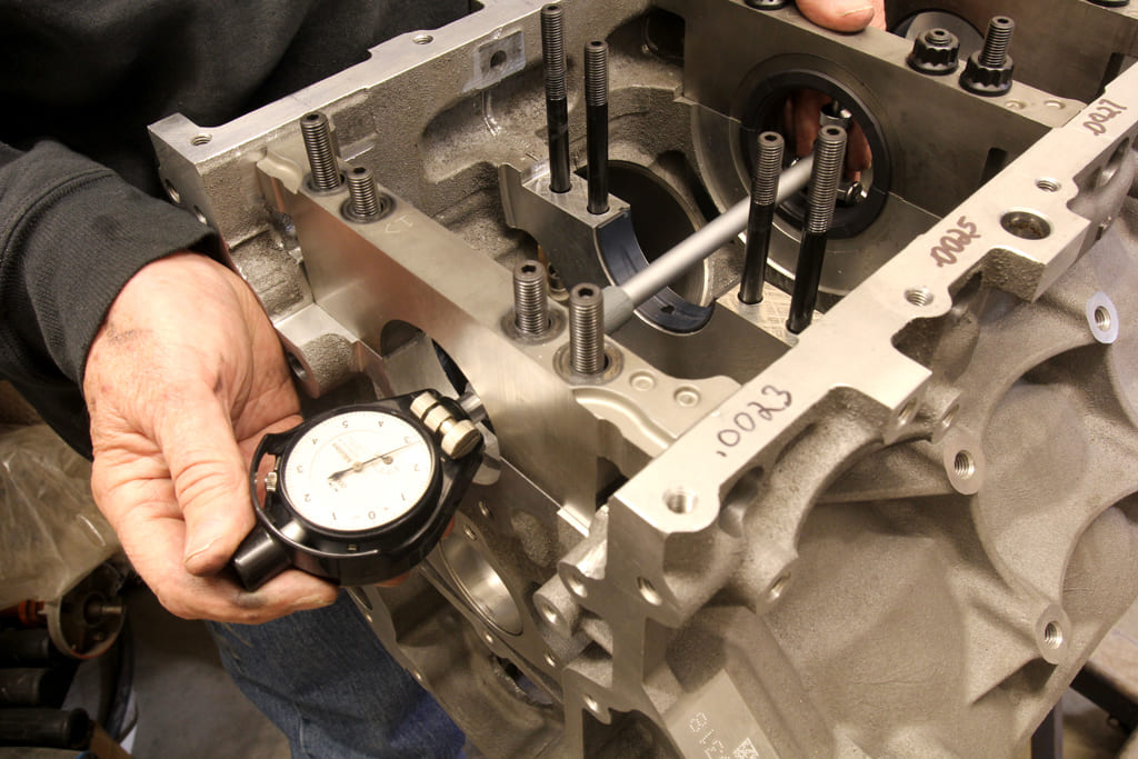
We also measured clearances for the rod bearings. We started with brand-new aftermarket Scat rods, and with a set of standard Mahle Clevite coated rod bearings, our clearances were all within a few tenths of our 0.0025-inch goal. So mixing and matching half shells was not necessary.
This entire process took a few hours to complete working slowly and carefully but the results were well worth the effort. Performance engine building is something that you should spend the extra time to perform correctly. While it does require patience and a small amount of skill, the results will be a very happy engine. The first time it fires will justify all the extra effort you put into the build.
Coated vs. Uncoated Engine Bearings
This test was performed at Shaver Racing Engines on a 383ci small-block Chevy where the bearings were subjected to 35 percent load at 1,500 rpm for 2½ hours using Driven synthetic oil. The following results were pulled from used oil samples evaluated by SPEEDiagnostix after each session. The parts per million (ppm) results are the accumulation of iron, lead, copper, tin, and aluminum. For the second set of results, we removed the iron to reveal the ppm outcome for just bearing material. The numbers indicate bearing wear can be drastically reduced by using coated bearings, especially when combined with synthetic oil.
| Uncoated | Coated | |
| Bearings | Bearings | |
| Wear | 25 ppm | 12 ppm |
| Wear (no iron) | 19 ppm | 5 ppm |
Parts List
These part numbers are just a few of the many Mahle Clevite options for an LS engine. There are also P-series performance tri-metal bearings as well as stock replacement bi-metal versions.
| Description | PN | Source |
| Mahle Clevite LS std main bearing, uncoated | MS2199-H | Summit |
| Mahle Clevite LS 1X (+0.001) main bearing, uncoated | MS2199-HX | Summit |
| Mahle Clevite LS std main bearing, coated | MS2199-HC | Summit |
| Mahle Clevite LS 1X (+ 0.001) main bearing, coated | MS2199-HXC | Summit |
Sources
Automotive Racing Products
(800) 826-3045
arp-bolts.com
Federal-Mogul (Tenneco)
(248) 354-7700
tenneco.com
King Bearings
(800) 772-3670
kingbearings.com
Mahle Clevite
(248) 347-9700
mahleclevite.com
SPEEDiagnostix
(704) 795-8828
speediagnostix.com
Click on this issue’s cover to see the enhanced digital version of Setting Bearing Clearance.


