
Fatman Fabrications Mustang II Conversion for the 1957-1959 Ford
By Brian Brennan – Photography by the Author
There are any number of reasons why you might want to rebuild the independent front suspension on your 1957-1959 Ford. However, in our street rod world the reasons and means to swap out old and tired independent front suspensions are readily available. And that brings us to the installation of a Fatman Fabrications (FF) Mustang II frame stub.
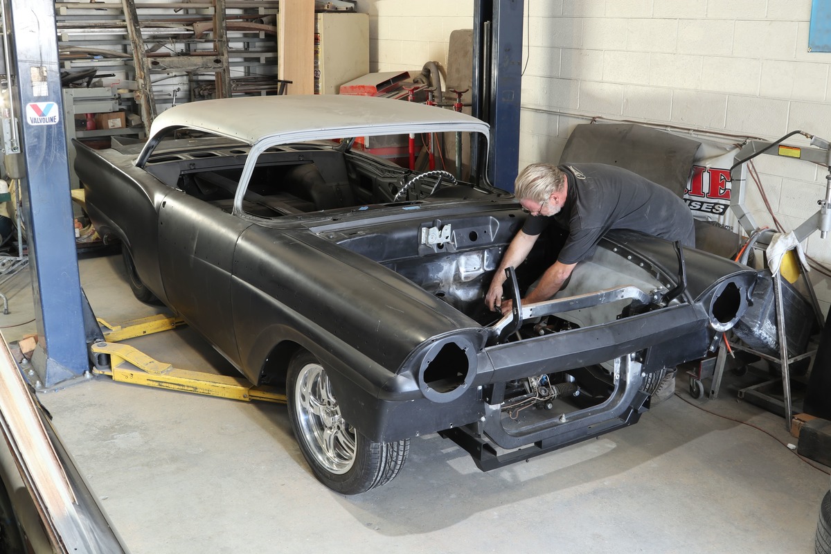
The 1957 Ford we followed in this story has the FF Mustang II frame stub that was installed at Kugel Komponents (KK) while Kev Elliott of Kev’s Rod & Custom (around the corner from KK) finished up the many sheetmetal projects both inside the engine compartment and elsewhere to make this Ford a driver. Originally the car had other work performed and a Ford Y-block was positioned. About a year later the car came back to KK to have a Kaase Boss Nine installed. Well, that massive engine wasn’t going to fit inside a stock engine compartment. The engine swap mandated that KK install the FF frame stub to gain additional engine compartment space that was required for the Kaase to fit.
A Little History
It was in 1957 that Ford developed a new frame where the perimeter framerails were outside the passenger compartment, yielding a safer car. At the same time Ford also went from 15- to 14-inch wheels, yielding a lower profile to further complement the new long and low design. Keep in mind that in 1957 the horsepower output ranged from 190 to 270 distributed through the three optional V-8s, 272, 292, or 312 ci. In 1958 the horsepower ranged from 205 to 300 among the three V-8s, 292, 332, or 352 ci. Then in 1959 the power (200 to 300 hp) and cubic inch (292, 332, 352) differed little from 1958. It should be noted that the Y-block isn’t a svelte V-8 by any stretch; the 272- to 312-inch V-8s weigh in at approximately 625 pounds. (Keep in mind that a small-block Chevy of the same era, cast-iron block, heads, and intake, weigh in at approximately at 575 pounds. Although the 1959 Corvette 283 weighed in at 535 pounds with its aluminum intake.) Also, consider you are dealing with approximately a 3,200- to 3,500-pound Ford passenger car. The performance that came from one of these early combinations wouldn’t be acceptable to any hot rodder today. Back in the day the Ford IFS had ball joints and by the time you replace all of the depleted pieces it’s a money swap and you still end up with something that doesn’t have the potential of the FF Mustang II frame stub. Oh, did we mention that the manual steering back in the day required those oversized steering wheels to allow you to negotiate parking lots and low-speed drives around the neighborhood without your forearms cramping up.

Why Use the Mustang II Frame Stub
The FF Mustang II frame stub is ideally suited for today’s engine swap on these mid-’50s Fords (or any of the OE-produced cars of that era). With the engine swap comes the demand for more space within the engine bay to account for the engine, headers, steering, and belt-driven accessories that all require additional clearance. Most of our engine swap headaches are answered by the use of an FF Mustang II frame stub; however, should you use a Coyote V-8 or other big-block Ford firewall modifications will still be part of the program.
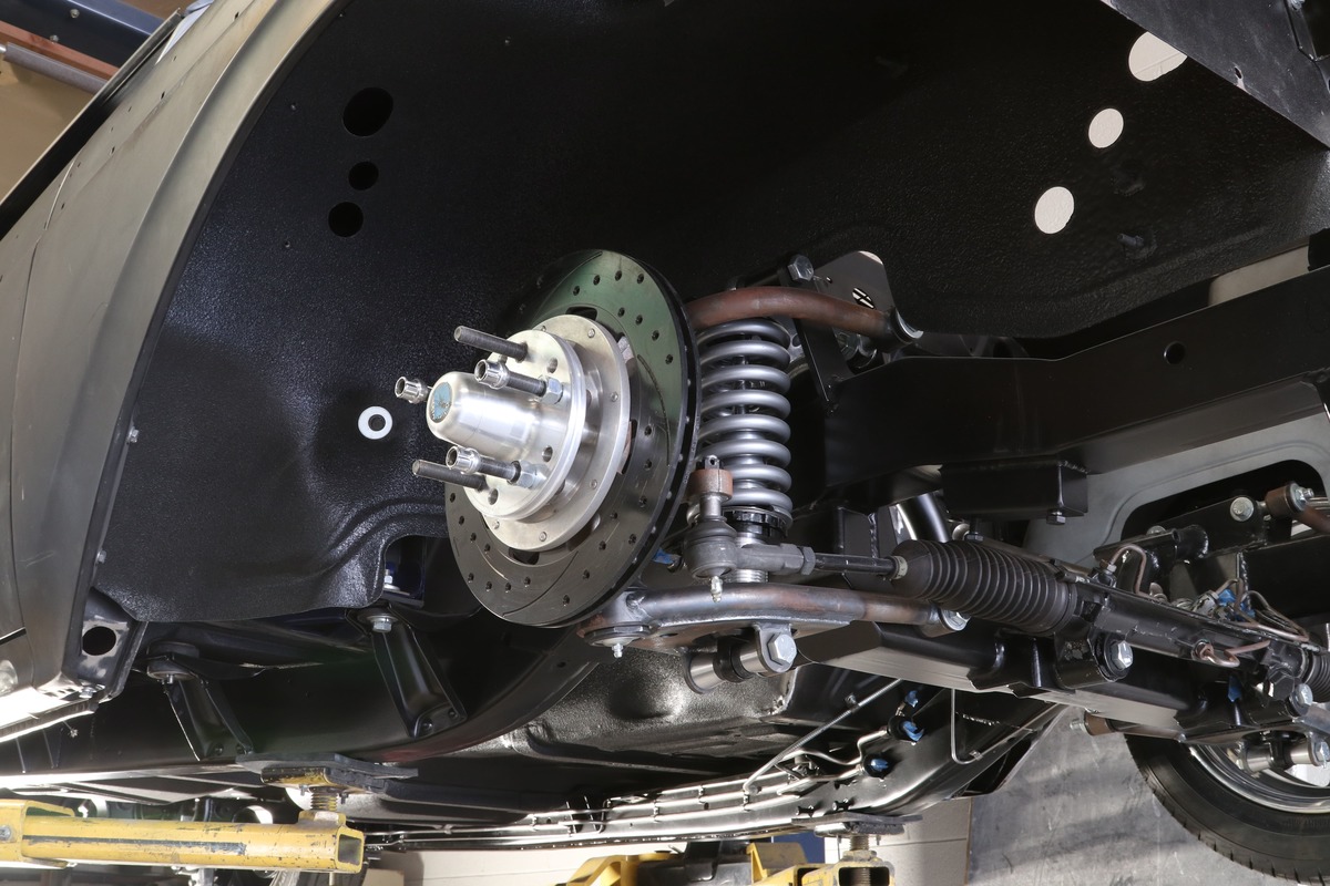
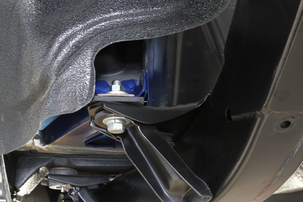
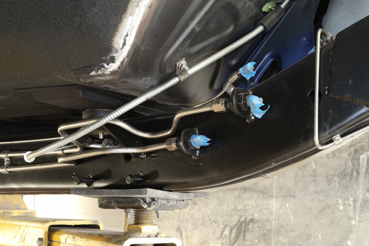
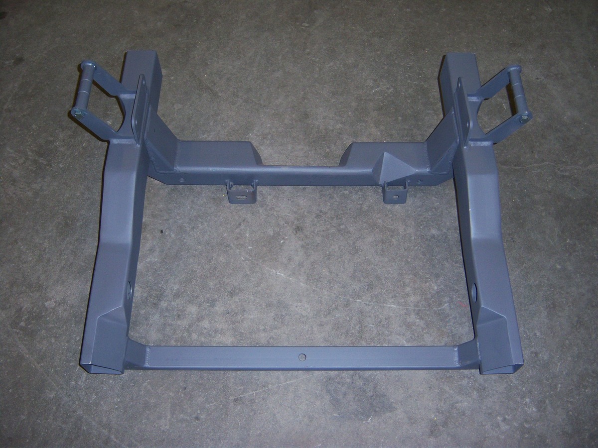
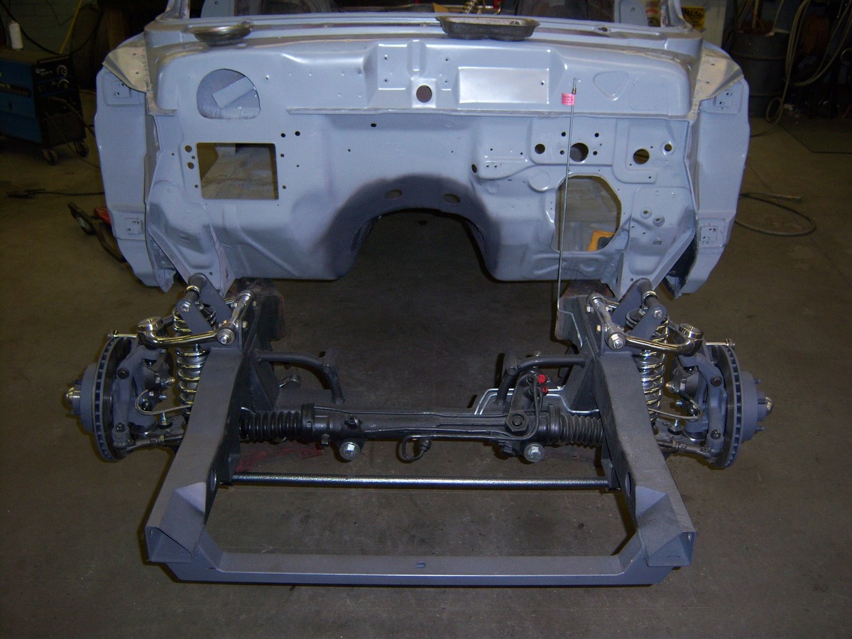
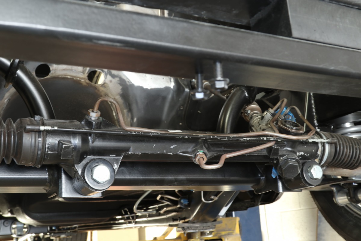
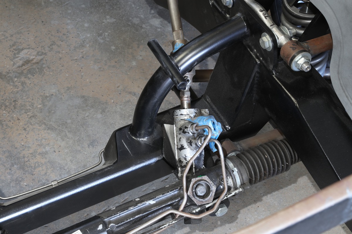
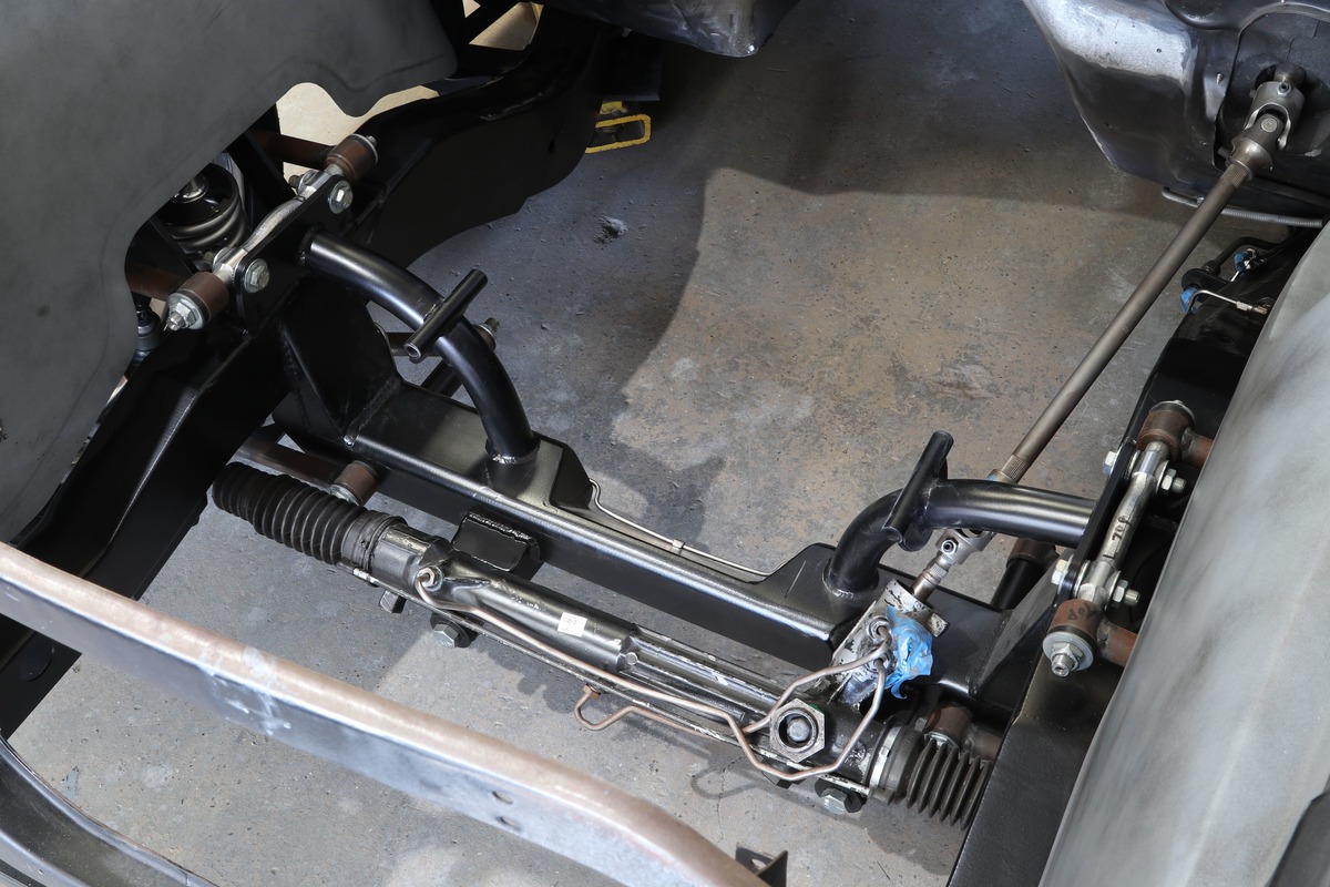
One significant shortcoming with the Fords of this era was the “valley” (drop) that trapped water; over time rotting (rusting) occurred in these dropped front crossmembers. If for no other reason this is a good idea to give serious consideration to installing the FF Mustang II frame stub with its flat crossmember. You should also consider the other positives when the frame stub is added. Once the crossmember is changed you now have the opportunity to upgrade to disc brakes and in our world the choices are wide ranging. Next up you are afforded the opportunity to get rid of the shock and coil spring technology (although viable) and in its place you can now install modern coilover shocks, which offer enhanced ride and handling characteristics. Even the lowly Mustang II spindle was an improvement over the earlier ’50s-era product. The Mustang II spindle has the advantage of offering increased bearing surface, therefore allowing enhanced performance and very workable under heavier hot rods. And then there is steering. The manual rack-and-pinion steering can be easily negotiated but should you install a power rack-and-pinion the steering becomes effortless and the smaller more desirable steering wheels of today become more suitable. Lastly, we hot rod owners do thoroughly enjoy our bling; the tubular A-arms come in raw steel but can be optioned-out for powdercoat, polished stainless steel, or chrome steel versions. Lots of good looks here.
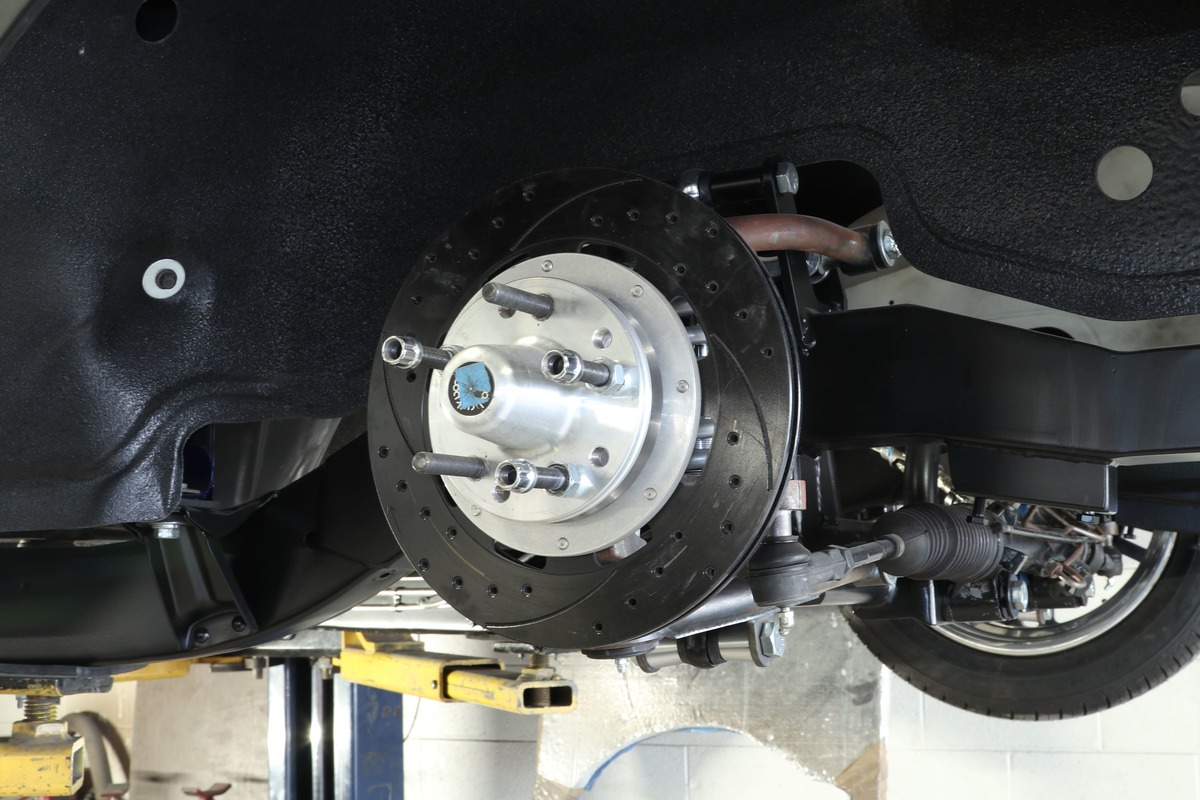
From a mechanical standpoint the noteworthy points achieved are better geometry, better replacement parts availability, better steering feel with rack-and-pinion, more engine room, more room for headers with the gearbox now out of the engine bay, the flat crossmember lowers the car while keeping the suspension travel and geometry correct, and increased ground clearance with the Mustang II–based flat crossmember as opposed to an OE-style crossmember with the center “drop.” Remember, no drop means no water and no forthcoming rust.
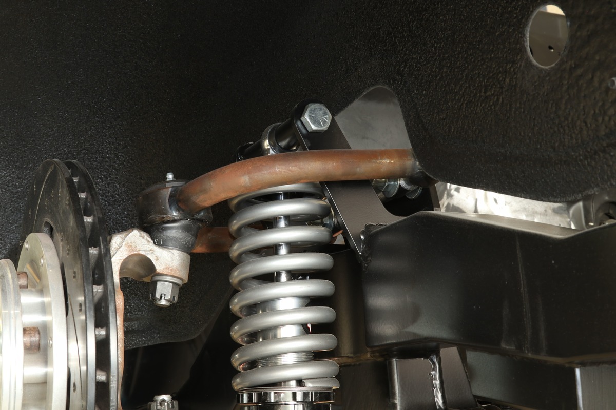
In our particular application the FF kit we used is the Stage III, which is immediately recognized by its use of coilover shocks. (Stage I was discounted some time back, Stage II is the OE-style coil spring with accompanying shock, Stage IV is used with airbags, and Stage V is used with ShockWaves.)

Ride Height
One area of consideration when building any ride is ride height. It’s been in vogue for years to have our rides sit low—and, lower is better. (That’s a conversation for a different story.) One of the choices you need to make is which “drop kit” from FF should you purchase? Since tire diameter directly affects ride height, you need to know that FF standard kits put the spindle center at the same height as the bottom of the frame. (There are other kits on the market that will sit your ride up to an 1-1/2 inches higher.) Measure the distance from the bottom of your frame to the lower control arm bolt … FF is 3-1/2 inches. Their ultralow kits put the spindle center 1-1/2 inches above the frame bottom. You will have a 1-inch plus or minus latitude in height with your final spring trim, so by changing tire diameter and spring trim you can generally get a 2- to 5-inch drop with the FF standard kit, and another 1-1/2 inches with their ultralow kits. FF will tell you that to get the right stance with the right kit and not by excessively cutting springs or drop spindles.
Basic Practices for Installation
Begin by setting your car on jackstands and not positioned under the suspension but the frame and you will want to make sure the car is level—front to rear and side to side. If necessary, you will want to use shims.
Next you will want to use a plumb bob to accurately mark on your garage floor with the locations of your axle centerline, the front body mount bolts, the bumper bolts, and radiator core support holes. Once you have marked the appropriate spots on the floor with a felt tip marker (you don’t want your markings to vanish mid-project) then you will want to take accurate height measurements. Record these; again, you may need them later. According to FF you want to be particularly accurate with the core support measurements since it locates the new frame stub and will directly affect your sheetmetal fitment when the time arrives.

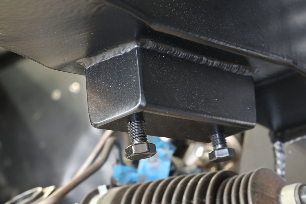
Note the front body mount hole; you will want to measure 10 inches ahead as this is the frame joint. Using a level, mark a vertical line. The better your cuts the better the fit will be. Use the 1/8-inch-thick sections supplied with the kit and tack them in place on the inside of the original frame top, bottom, and side. The joint is figured at 10-1/4 inches on the new frame stub to provide a 1/4-inch weld gap with the backup plates to ensure full weld penetration. The small wedge of metal supplied is used to blend the mismatch of old and new frame depths.
Now you are ready to set the FF Mustang II frame stub in place. Make sure to use clamps and tack welds to hold the joint in place and a jack, or adjustable jackstands, to precisely locate the recorded height of the radiator support mount top surface. Why is this important? This is the reference point for all other measurements.
It’s now time to tach weld the entire frame stub into position. Once this is done you will recheck all of your measurements and make sure nothing has moved. If this is the case then your sheetmetal fitment shouldn’t be an issue. To be sure you can remount the hood and bumper to check, which is time-consuming but time well spent, there’s a sequence to check axle centerline to fender fitment as well as checking ride height. Again, there are no shortcuts when it comes to reading and following instructions.
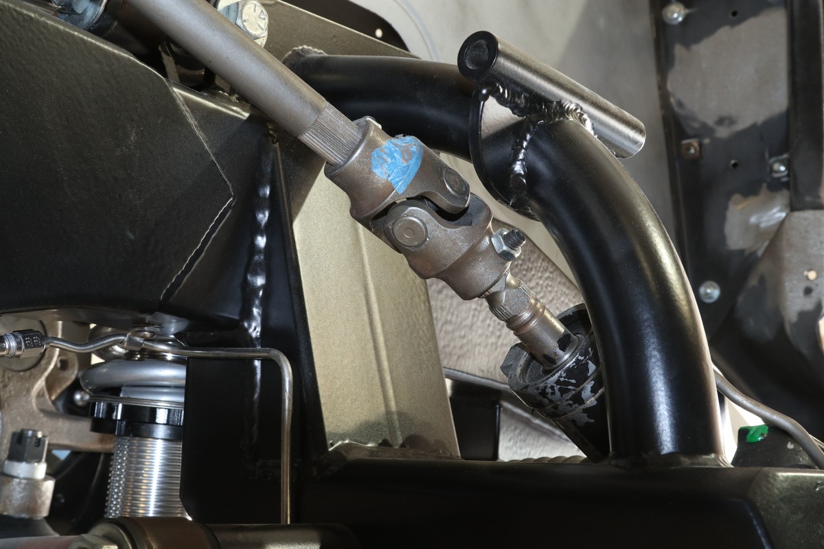
Lastly, now is the time to install the remainder of the Mustang II components. Your new steering may require two or three U-joints and this will be determined by the type of engine, motor mounts, and how your exhaust is routed. (Word to the wise, according to FF make sure to keep the U-joints in phase.) If three U-joints are required you will also need to use an idler bearing.
With an updated suspension under your 1957-1959 Ford you will enjoy your project a great deal more. MR
Sources
Fatman Fabrications
(704) 545-0369
fatmanfab.com
Kev’s Rod & Custom
(714) 686-8992
Instagram: @kevsrodandcustom
Kugel Komponents
(562) 691-7006
kugelkomponents.com