Good Brakes Result From Proper Selection and Installation
By Brian Brennan – Videography by the Author – Photography by Tim Sutton
There’s an old expression that goes something like, “You should drive only as fast as you can stop.” There’s a great deal of truth in this saying. However, no matter the quality of the brake system it will only function as well as it matches its usage and its installation.

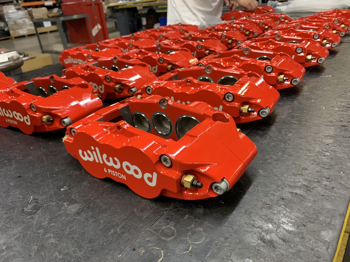
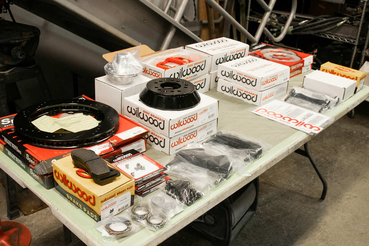
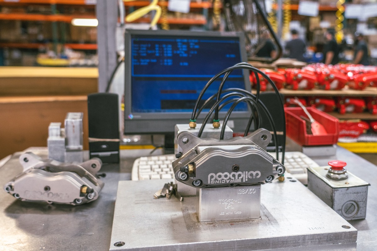
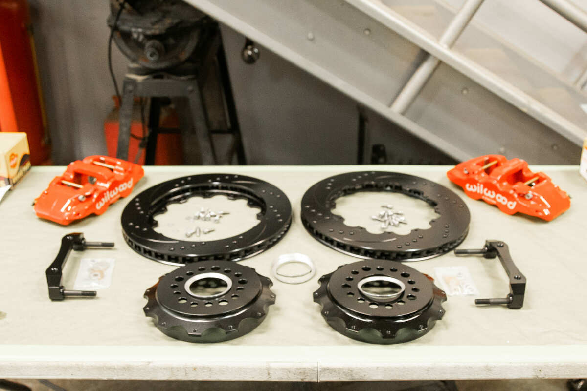
We are going to walk you through some brake basics and follow along with an installation of a Wilwood Engineering brake package, all the while passing along some brake-wisdom tidbits. Also, nothing replaces the detailed instructions that are provided by Wilwood Disc Brakes and are also available anytime online. Visible in the current photos are a front and a rear Wilwood kit and the Aerolite 6R front kit (PN 140-10641) used with a Wilwood ProSpindle 2-inch drop (PN 830-9807) and a 14-inch-diameter drilled/sotted/vented rotor. (There’s also a standard height spindle, PN 830-10832.) In back The Aerolite 4R rear kit (PN 140-11270) is used with the OE-style parking brake and the 14.25-inch-diameter drilled/slotted/vented rotor. A couple of additional items you will need to have aside from tools will be permanent thread sealer, such as Loctite 271 (red) and Wilwood Hi-Temp 570, DOT3 brake fluid.

Rotors
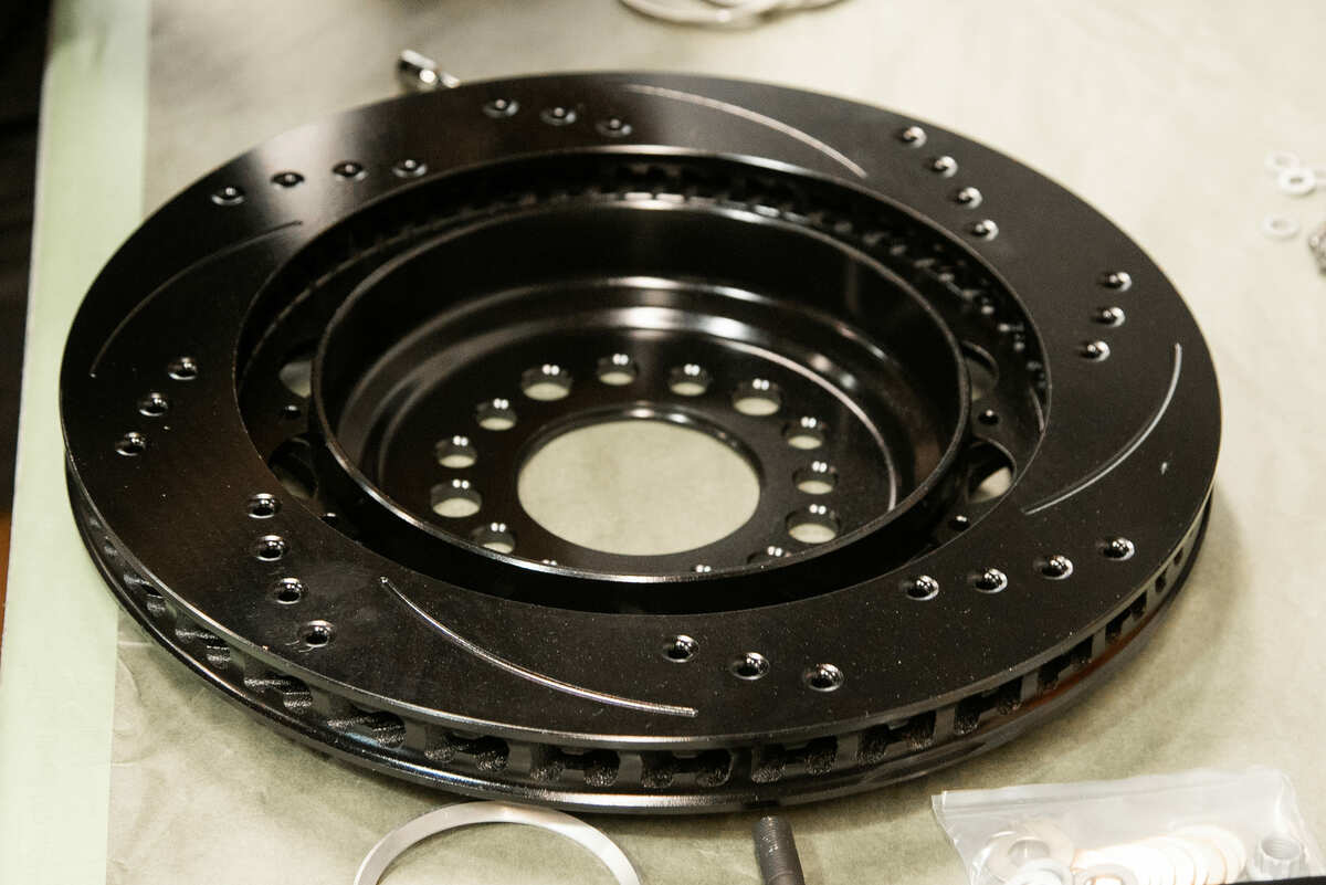
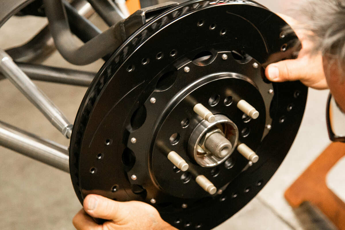
A word on rotors with directional cross-drill and face slot pattern. These rotors do have an aesthetic appeal but they also have an accountable performance relevance. The venting and cleaning action of the hole and slot pattern does help to reduce pad glaze and minimize pad buildup on the rotor faces. These black electro coat rotors have a resistance to corrosion and the accountable performance is a smoother engagement pedal feel and a consistent pad response—and they look cool!

Master Cylinder Mounting Position

Keep in mind that not all master cylinders are mounted in the same location. By that we mean it’s customary for early hot rods (pre 1949) to have their master cylinders mounted below the floorboards coming off of the frame, hence below the calipers or drums. On the other hand, cars from the ’50s forward primarily maintain the factory hanging firewall mounting position, hence above the calipers or drums. Why is this important? Brake pedal leverage ratios and the use, or lack thereof, of residual pressure valves are two critical components to a well-tuned brake system.
Brake Pedal Ratio
When using the factory master cylinder firewall mount and factory pedals this shouldn’t be an issue as the math was already done by the OE. However, with early hot rods we find through the floorboard pedal assemblies as well as under the cowl mount pedal assemblies the pedal ratios need to be checked. Keep in mind it’s desirable to maintain a suitable pedal ratio of 3:1 to 5:1 for power brakes and a 6:1 to 7:1 ratio for manual brakes. When purchasing brake or pedal assembly kits from a manufacturer, such as Wilwood, they have taken this into account and will make sure to match pedal ratio and master cylinder bore size to ensure a proper pedal “feel” and performance.
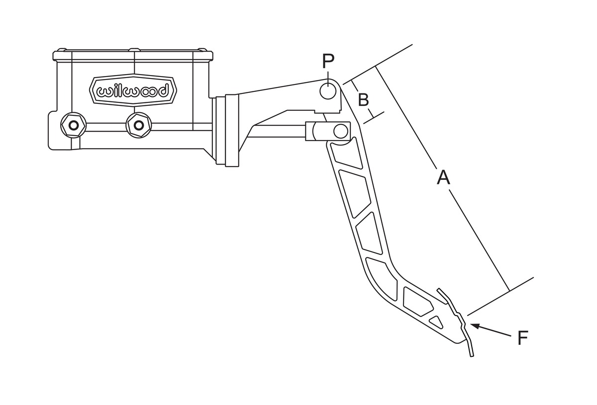
However, should you find yourself on your own and need to come up with a brake pedal, keep the following in mind. Pedal ratio is calculated by measuring the straight line distance from the center point of the pedal pivot to the middle of the foot pad (measurement A, photos 6 and 7) and then dividing that number by the distance from the center point of the pedal pivot to the center point of the pushrod attachment location (measurement B, photos 6 and 7). If measurement A is equal to 10 inches and measurement B is equal to 2 inches then the pedal ratio is 5:1 (A divided by B equal pedal ratio).

Residual Pressure Valves
Another key point comes into play when using either four-wheel disc brakes (as in this story) or disc in front and drum in back (common); that’s referred to as fluid flowback to the master cylinder and the need for residual pressure valves (RPV). There’s the 2 pound (blue) and the 10 pound (red); oftentimes they’re simply referred to by their color as this seems to remain consistent from manufacturer to manufacturer. The color coding also makes it simple to make sure you have the correct value controlling the front and/or the rear.
If your master cylinder is lower or higher than the drum brakes being used, no matter what you have to use a 10-pound (red) RPV inline with these brakes. Why? The springs that retain the drum shoes have enough force to compress your wheel cylinder. As it compresses the wheel cylinder, it will force the brake fluid back into the master cylinder, forcing the driver to perform the unwanted task of “pumping the brakes” before they work.
For disc brakes, it’s much easier. If the calipers are higher than the master cylinder (frame mount master cylinders), we suggest using a 2-pound blue RPV valve. The elevation of the calipers being higher will slowly force the brake fluid from the calipers back to the master cylinder.
If the master cylinder is mounted on the firewall and you are using a hanging brake pedal, there is no reason to use the 2-pound blue RPV valve(s) for your disc brakes.
Adjustable Proportioning Valve
A word on adjustable proportioning valves. Front-to-rear caliper piston sizes, rotor diameters, and pad compounds must be initially configured to provide the correct range of vehicle bias when using a single-bore/tandem outlet master cylinder. If excessive rear brake bias is experienced, an inline adjustable proportioning valve can be used to decrease the rear line pressure to help bring the vehicle into balance. If excessive front brake bias is experienced, first consideration should be given to increasing the rear brake bias to bring the vehicle into overall balance. On early hot rods that use bigs ’n’ littles (tire and wheel) combinations this is especially the case.
Pedal Feel
Once you have the proper mechanical pieces in place it’s time to check the pedal feel. You can test the brake pedal by assuring yourself that the pedal “feel” or “pressure” is firm. Under all circumstances the pedal shouldn’t be spongy and the pedal should stop at least 1 inch from the floor under heavy braking. If the pedal starts out firm but then sinks to the floor you will want to check the system for brake fluid leaks. If there are any leaks at the fittings you will want to determine if they were properly tightened or was it overtightened and a crack has occurred. Next, if the pedal goes to the floor and after bleeding the system the problem doesn’t go away (and there are no leaks) then you will need to consider going to a master cylinder with increased capacity (a larger bore diameter).
Pad & Rotor Bedding
Find a stretch of road that is both a clean and a clear surface and also free from traffic. (Really, you do not want to have to deal with traffic during this procedure.) You know the old saying, “Forewarned is forearmed”? Well, it would also be wise to try to stay within the designated speed limit posted. Wilwood routinely recommends finding a road that has a speed limit equal to or greater than 45 mph.
Start with hard, panic stops from 45 down to 20 mph. For a car that weighs 3,000-3,500 pounds (which takes into account most pre-1949 hot rods and late-model midsize cars through the mid ’50s) you will want to perform these stops about six to eight times. Another tip: Make sure you have your windows down. Why? After about six to eight hard panic stops you should start smelling brakes. This is good. That means you are saturating the brake system, allowing the calipers, rotors, and brake pads (critical) to get hot. This will help get the binders that hold the brake pad friction together hot and onto the face of the hot rotor. This too is desirable. If they feel as if they’re fading, that too is a good thing. It means you are saturating the system. Once you start smelling the brakes you will want to perform two more hard (panic) stops from 45 to 0 mph. This will ensure we have fully saturated the brake system.
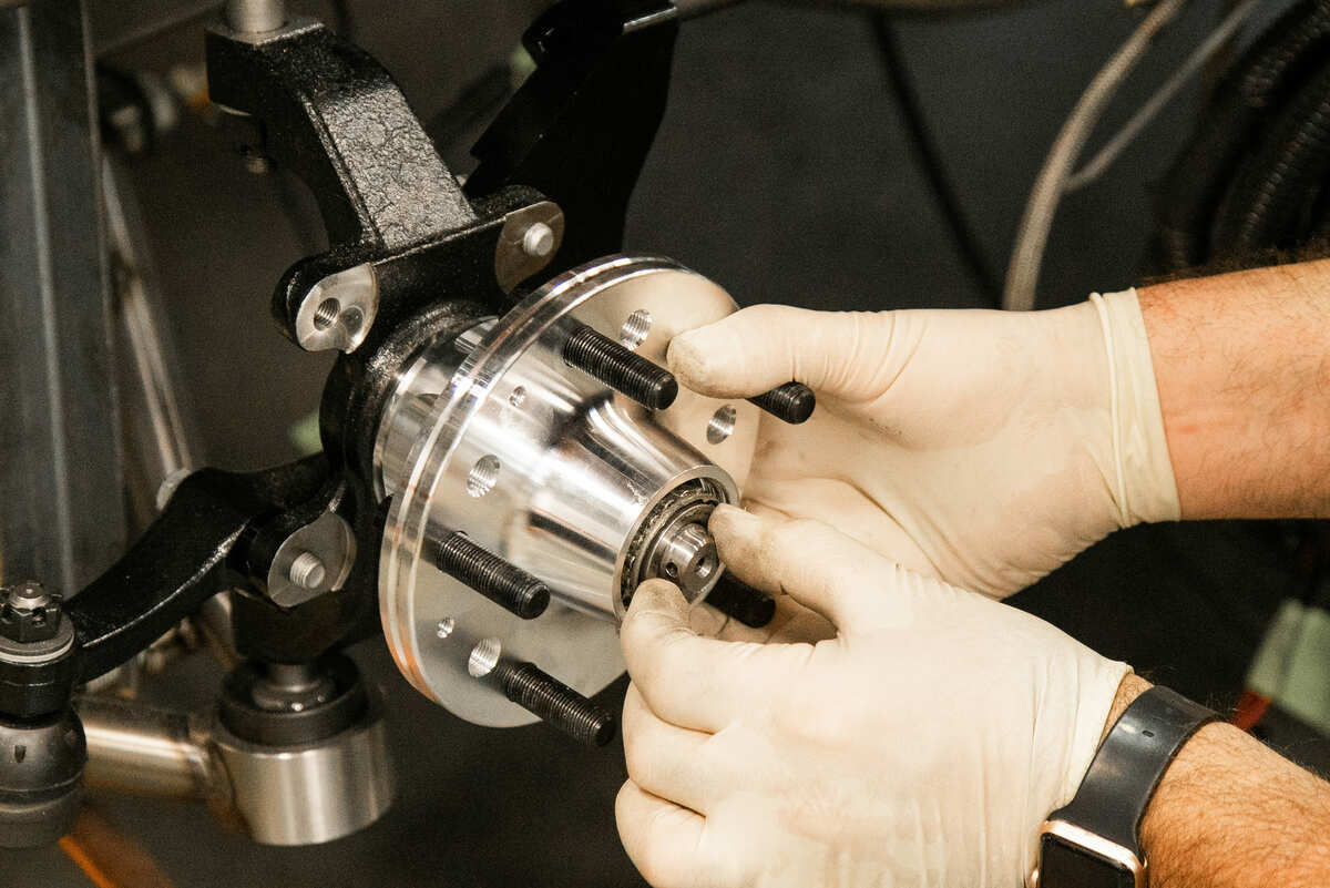
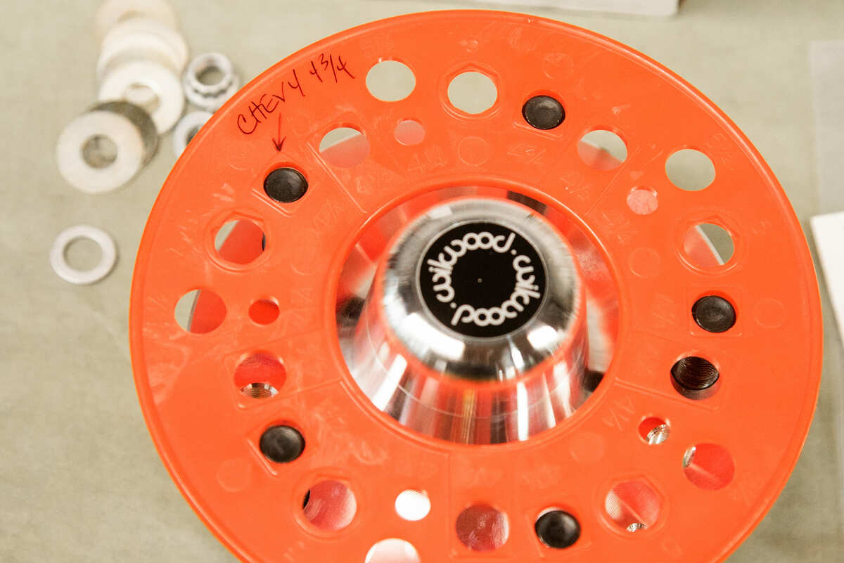
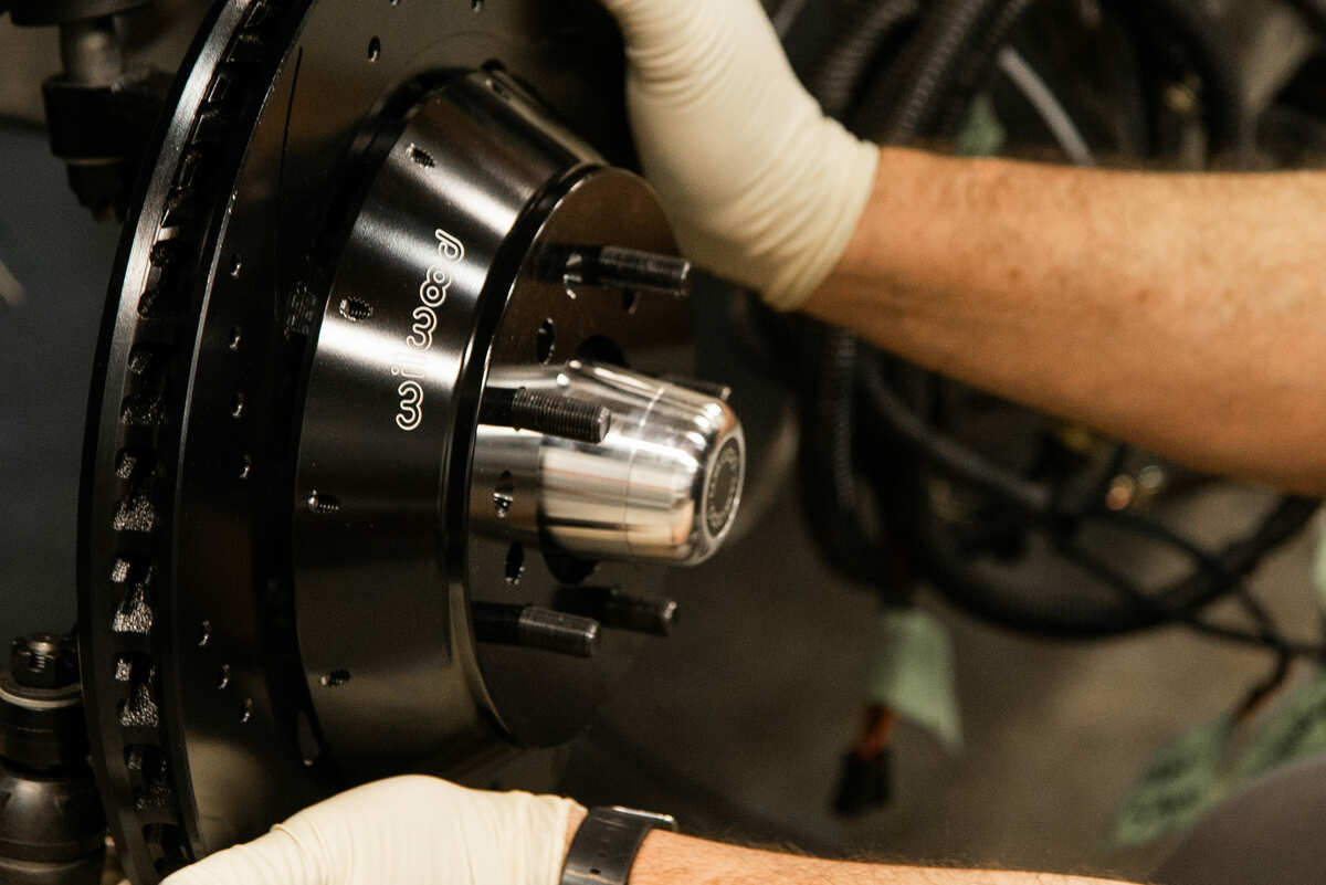
The hub with cone and inner bearing in place. Make sure to properly adjust the retaining nut … follow instructions. Once adjusted then the O-ring and dust cap can be installed.On your last stop, get out and inspect the brake system. Make sure you see that the rotors have some color to them; you are looking for a slight blue/purple hue to the face of the rotor. Put your hand up close to (do not touch) the wheel. Is it warm? Good! The brakes are doing their job. The last thing you will want to check is your mechanical expertise … how well did you perform all of the functions? Look inside the barrel of the wheel checking for any possible brake fluid droplets or debris that shouldn’t be there. Take one last hot lap around your car inspecting your aluminum wheels and make sure there isn’t any brake fluid on them.
After a visual check is made, jump in and take the car for a drive, allowing the natural flow of air to pass over the brake system cooling it as much as possible, and remember to use as little brake as possible. Once this is complete, a 10-15-minute drive, go home and park your car, letting the brakes cool down to the ambient air temperature. The next time you go for a drive you should experience the ideal braking and there should be minimal brake pad noise (squeak).
Assembly of the Front Brake Kits
We are going to present an overview on how the brakes are installed, front and rear. But we will give more insight in the photo captions so combining the info here and, in the captions, should give you a good overview on how the brakes are assembled. Remember, the Wilwood-delivered instructions will be the most detailed information available and should be thoroughly read.
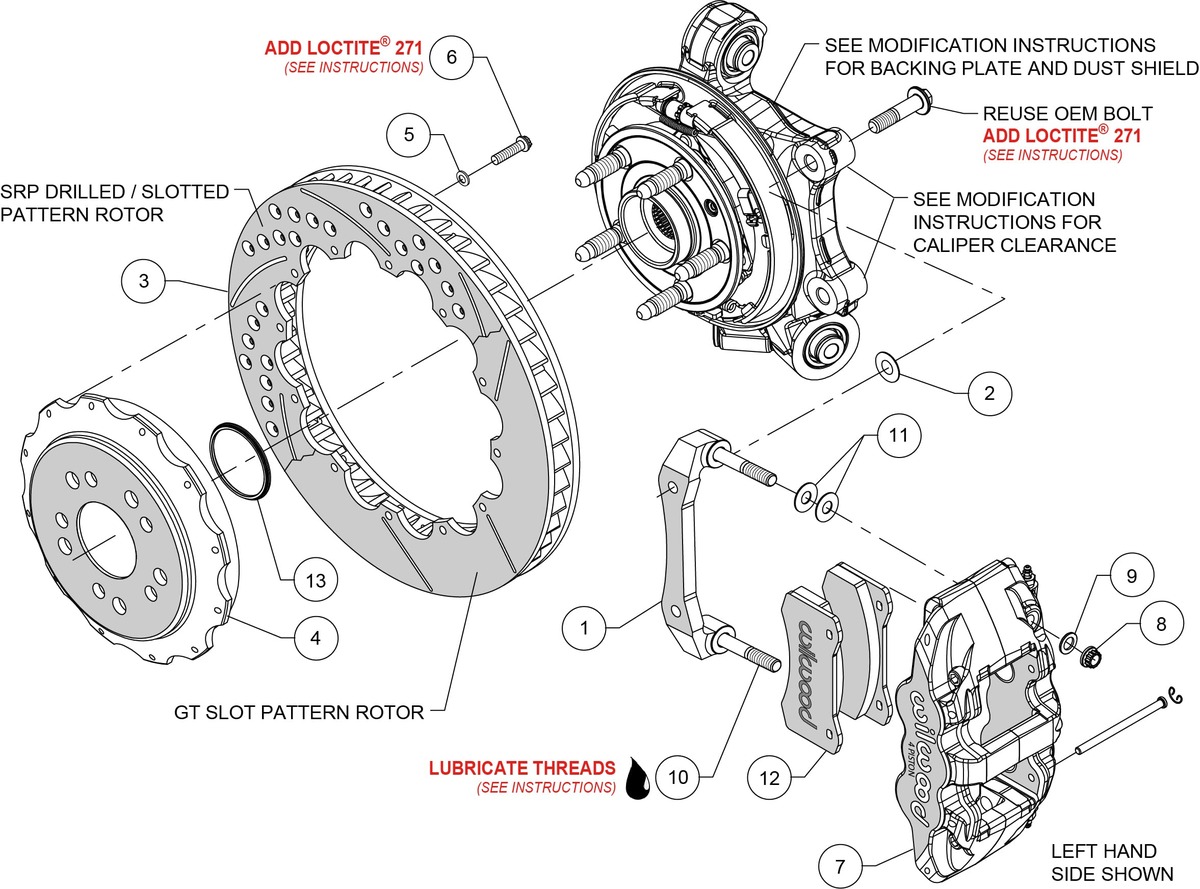
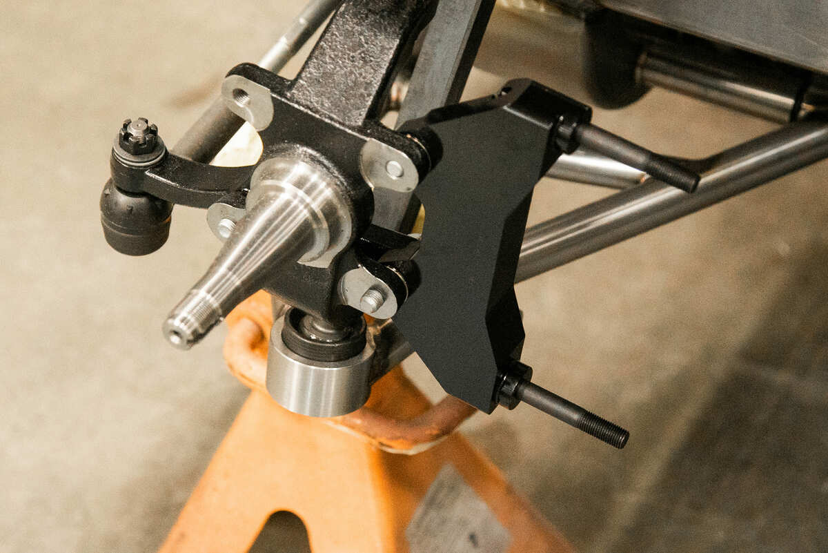
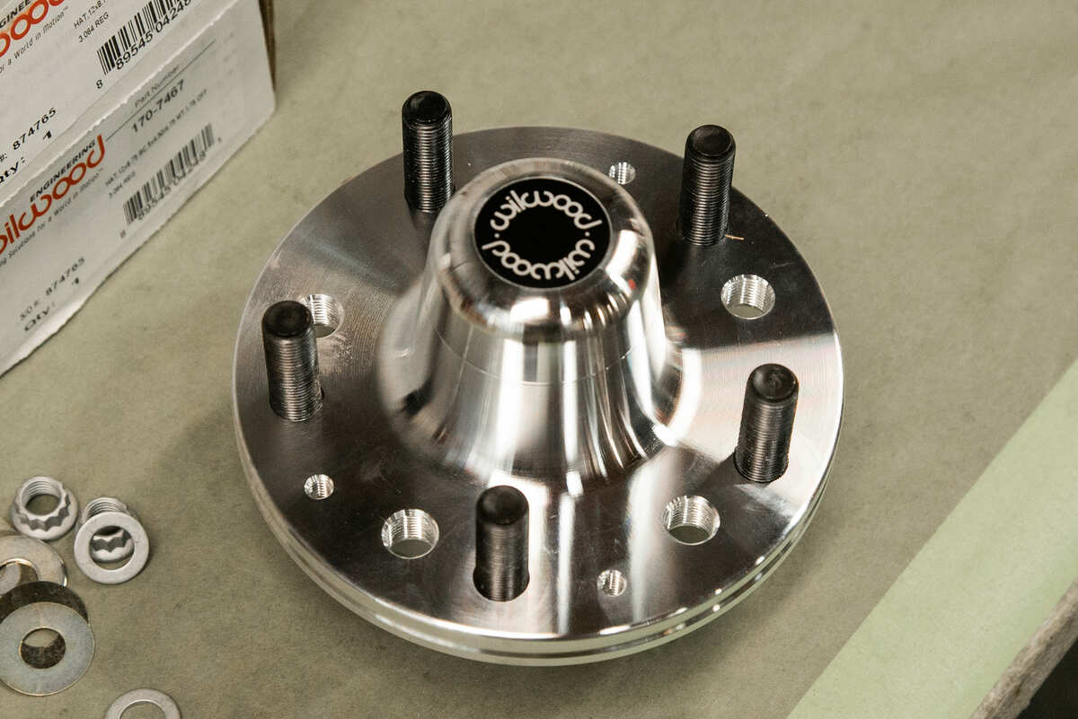
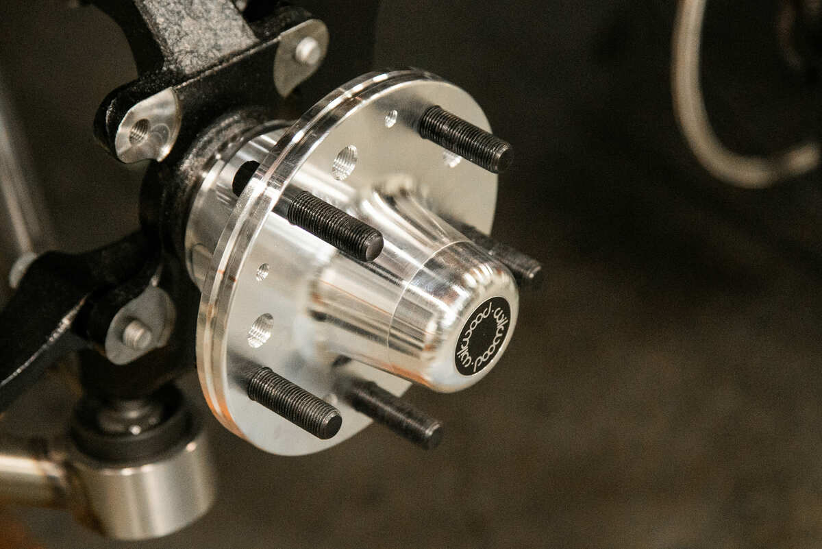
In our example we are using the Wilwood ProSpindle 2-inch drop spindle. With the spindle prepped and ready to go you will begin by positioning the steering arm to the spindle. Here you will want to use Loctite 271 on the threaded surfaces of the hardware. Next you will want to make sure that the bolt pattern of your hubs match that of your wheels. Once bolt pattern is verified make sure the wheel studs are in position and begin to assemble the brake bearing using the recommended grease and adjusting nut. Following the proper adjusting nut specifications then you will install the O-ring and press fit dust cap.
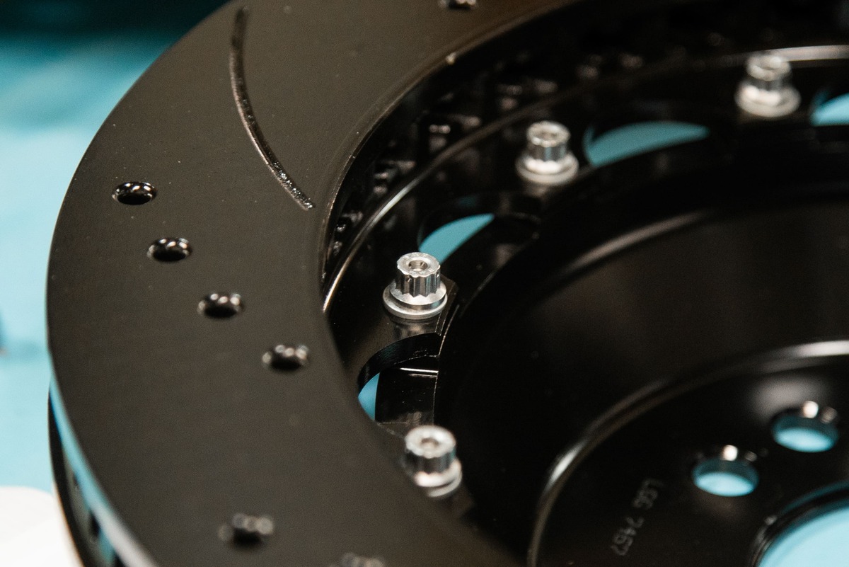
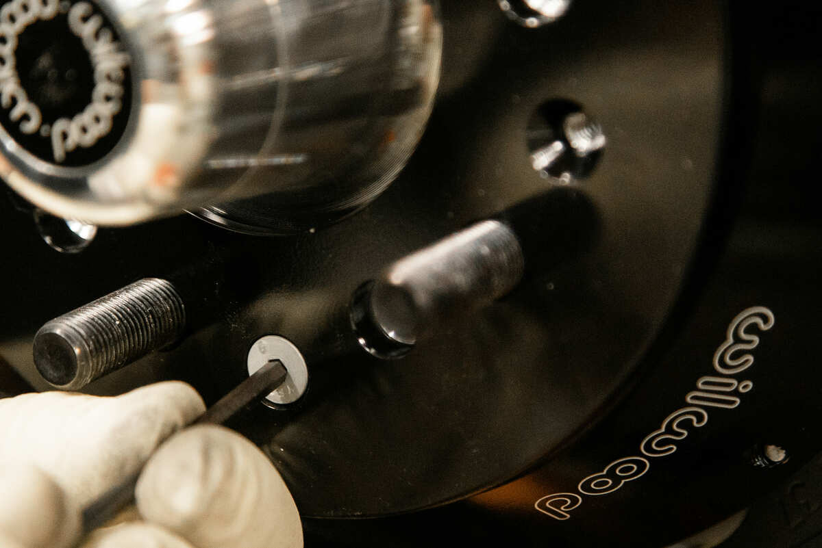
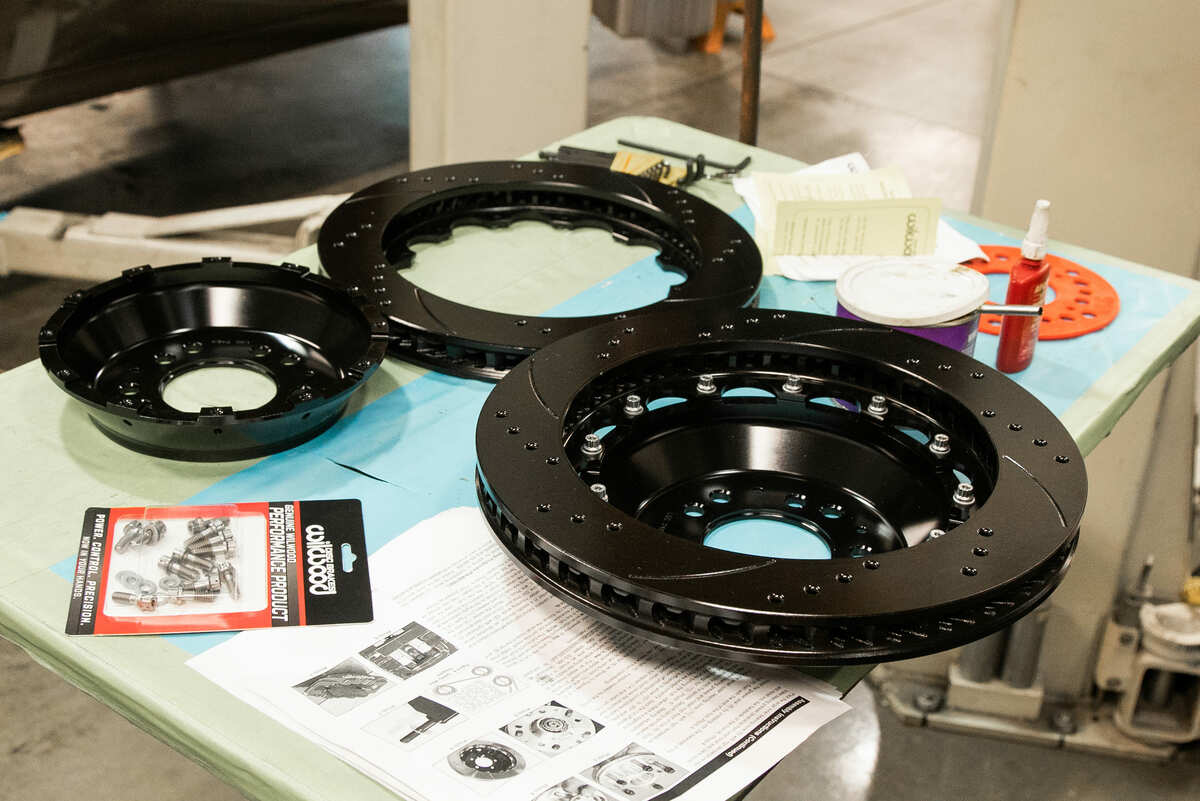
The rotor is then attached to the hat using the 12 bolts and washers provided in the kit. Keep in mind this hardware will also need the use of Loctite 271 and this hardware needs to be torqued in an alternating sequence to 155 in-lb. (Careful, that’s “inch” pounds!) Although not shown in this installation, many hot rodders go the extra step and use standard 0.032-inch-diameter stainless steel safety wire. Once the hat/rotor assembly is slid onto the hub, make sure to align the small countersunk holes in the hat with the small threaded holes in the hub.
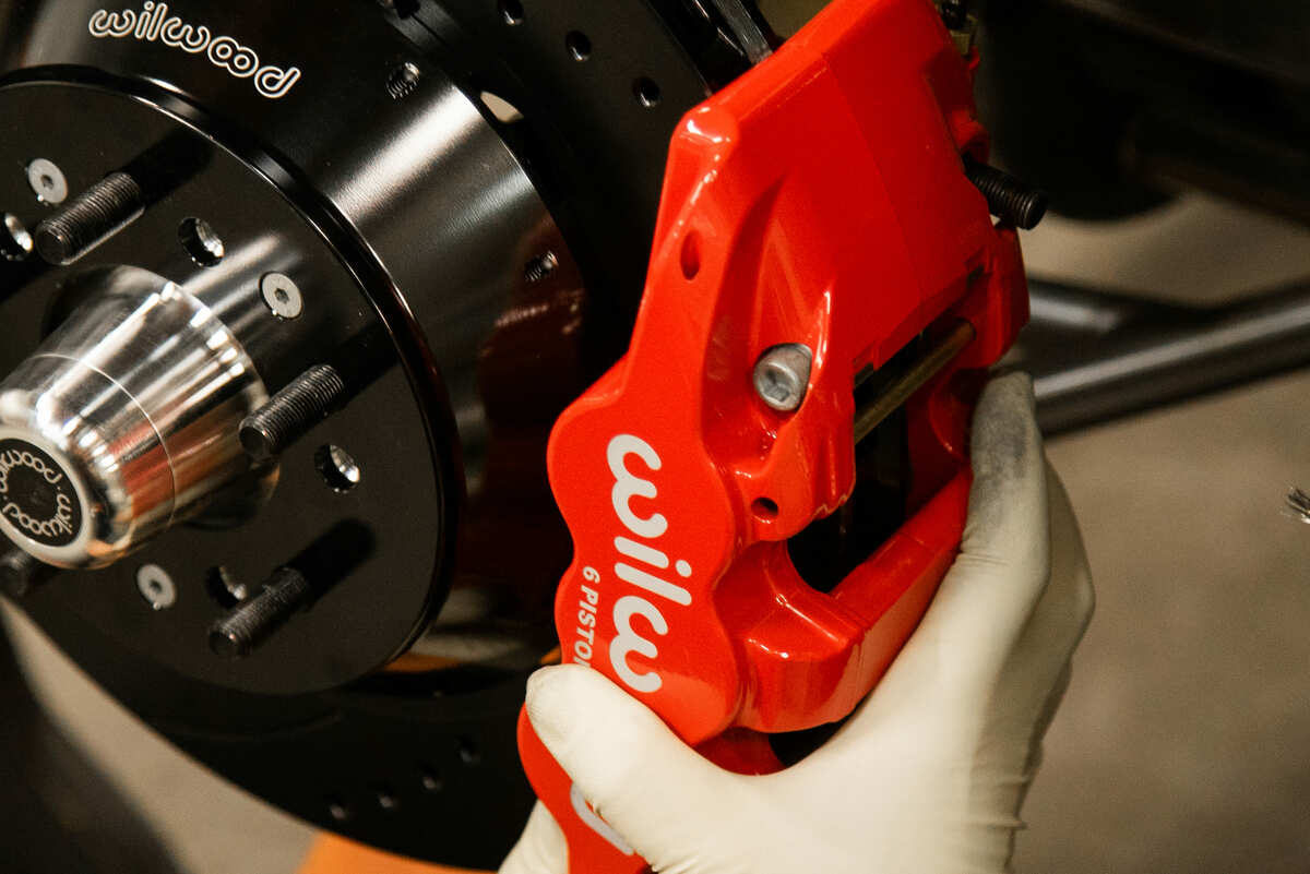
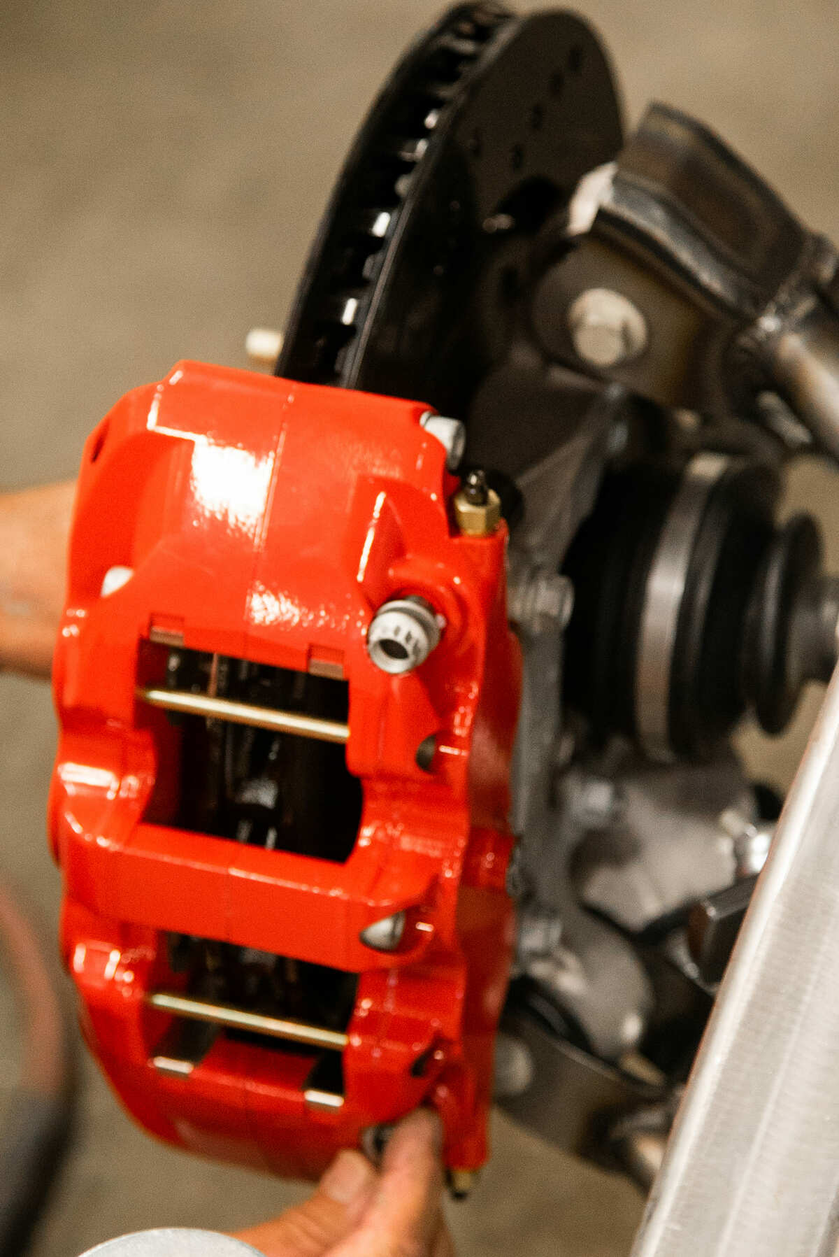
Next take the three (provided) flathead screws and torque to 85 in-lb. Once you are ready to install the calipers remember there is a right- and a left-hand caliper; make sure to install the correct caliper per side. Use the provided hardware and also make sure to use a lightweight oil to lubricate the caliper mounting studs. There is a procedure to make sure the calipers are aligned properly and there are also shims provided so that you can get the alignment correct.

Assembly of the Rear Brake Kits
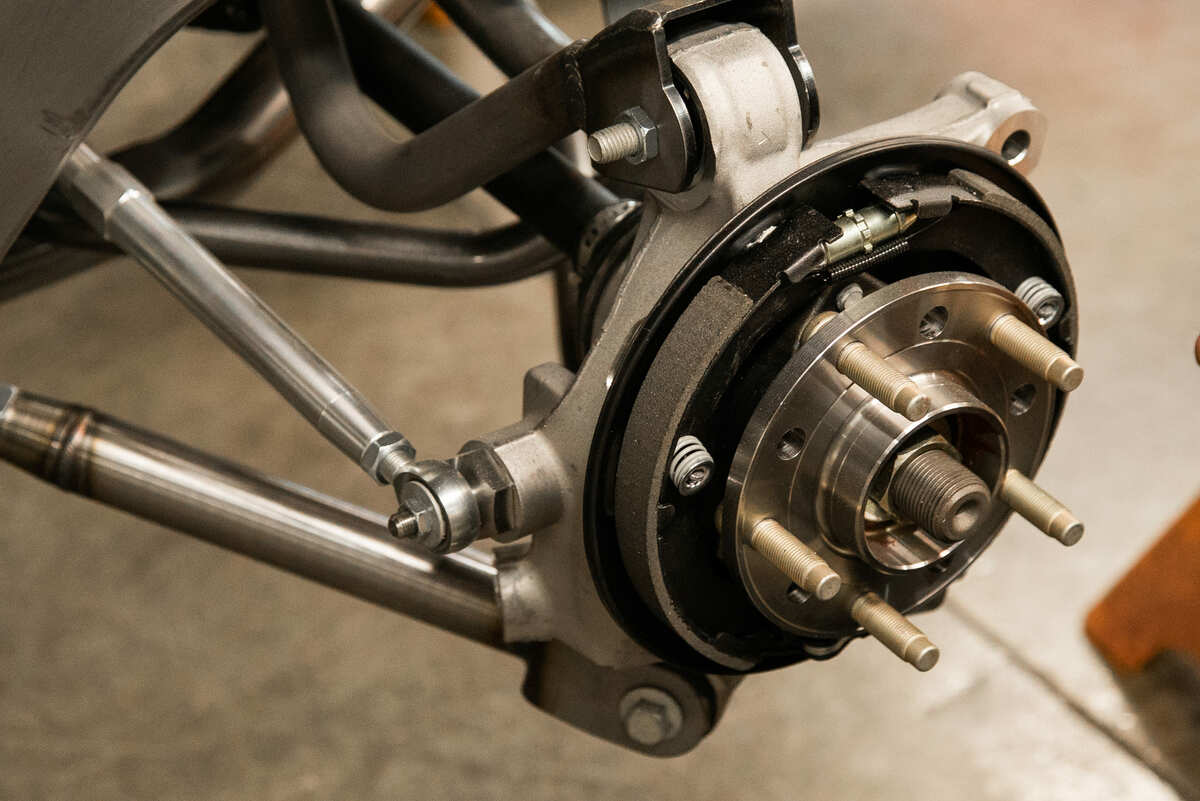
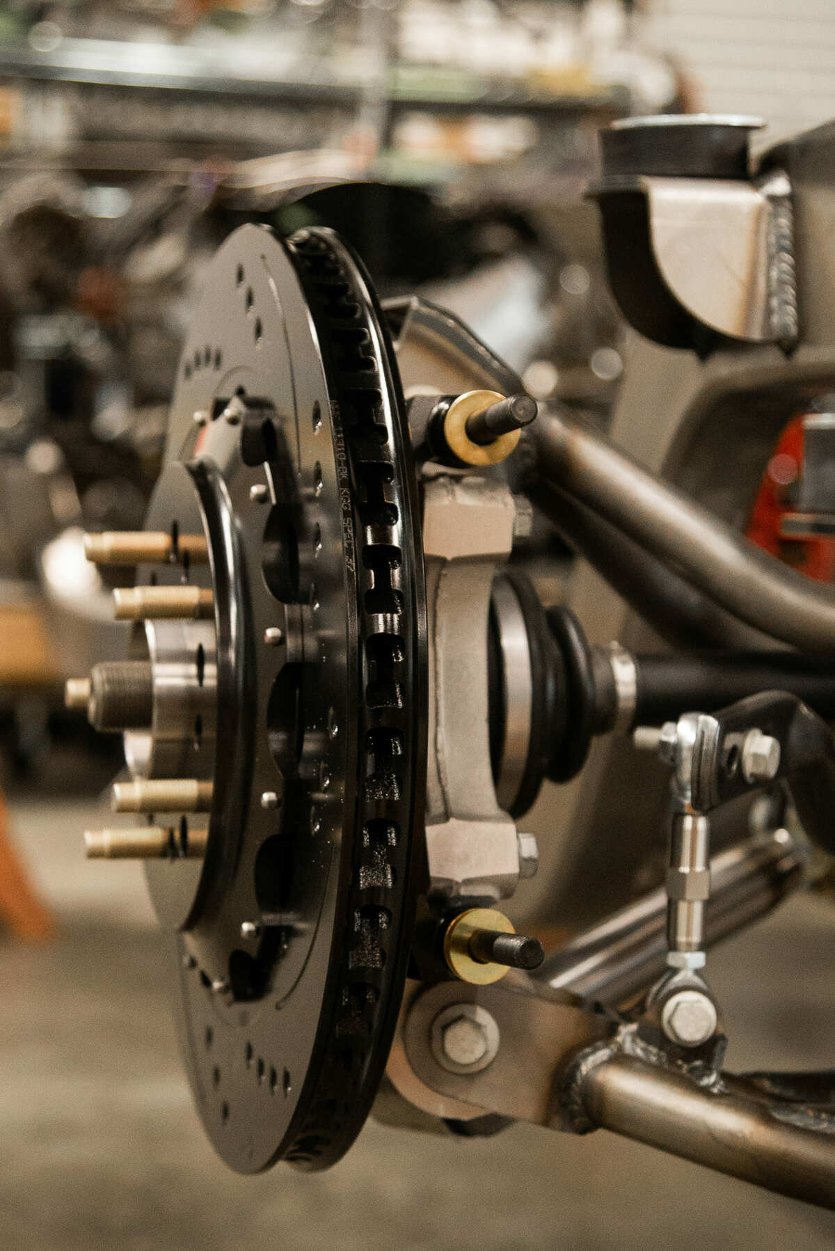
The rear kit while similar in installation to the front, when it comes to mounting the calipers there are noted differences with the hub assembly because of the integral parking brake. The Aerolite 4R with OE parking brake and 14.25-inch-diameter drilled/slotted/vented rotor is intended for 2010-present Camaros and 2008-2012 Cadillac CTS axle hubs. As such, hot rodders have chosen this kit as it works well with the Art Morrison Enterprises (AME) Multilink independent rear suspension, which is based on Corvette hubs and Camaro knuckles and works well with the Wilwood system.

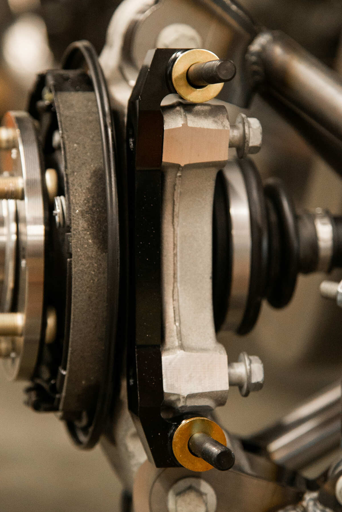
You will want to start by attaching the caliper mounting bracket, orienting it so that the caliper will be mounted on the backside of the axle pointing to the rear of the car. Next up comes the rotor and hat and it goes together similar to the front with the hat attaching to the rotor using washers (0.265 x id x 0.500 od x 0.063-inch thick) and bolts (1/4-28 x .750-inch long 12 point) using Loctite 271 on the threads and torque the bolts to 140 in-lb. (Again, safety wire can be used for an additional margin of safety.) You can now insert the pads into the calipers. This is a straightforward procedure, not unlike changing disc brake pads you have undoubtedly done many times before.
Next up are the brake lines will need to be installed and this will be best accomplished by good professional judgment. If you are unsure, check with an expert who understands what it is you are doing. Lastly, you will want to check wheel fitment as well as bleed the brakes. With the wheels make sure that they spin freely and there’s no interference/rub with any of the brake components.
Brakes have become both a performance as well as an aesthetic enhancement. Knowing this hot rodders have also gone to large window wheels to show off their latest brake kits. A lot of time and money is invested in high-performance brake kits, making sure they are installed properly will make all of the effort worthwhile. MR
Sources:
Wilwood Engineering
(805) 388-1188
www.wilwood.com
Hot Rods & Hobbies
(562) 424-9425
www.hotrodsandhobbies.com