

Degreeing a Camshaft and Deciphering Static Compression Ratio
By Ryan Manson – Photography by the Author
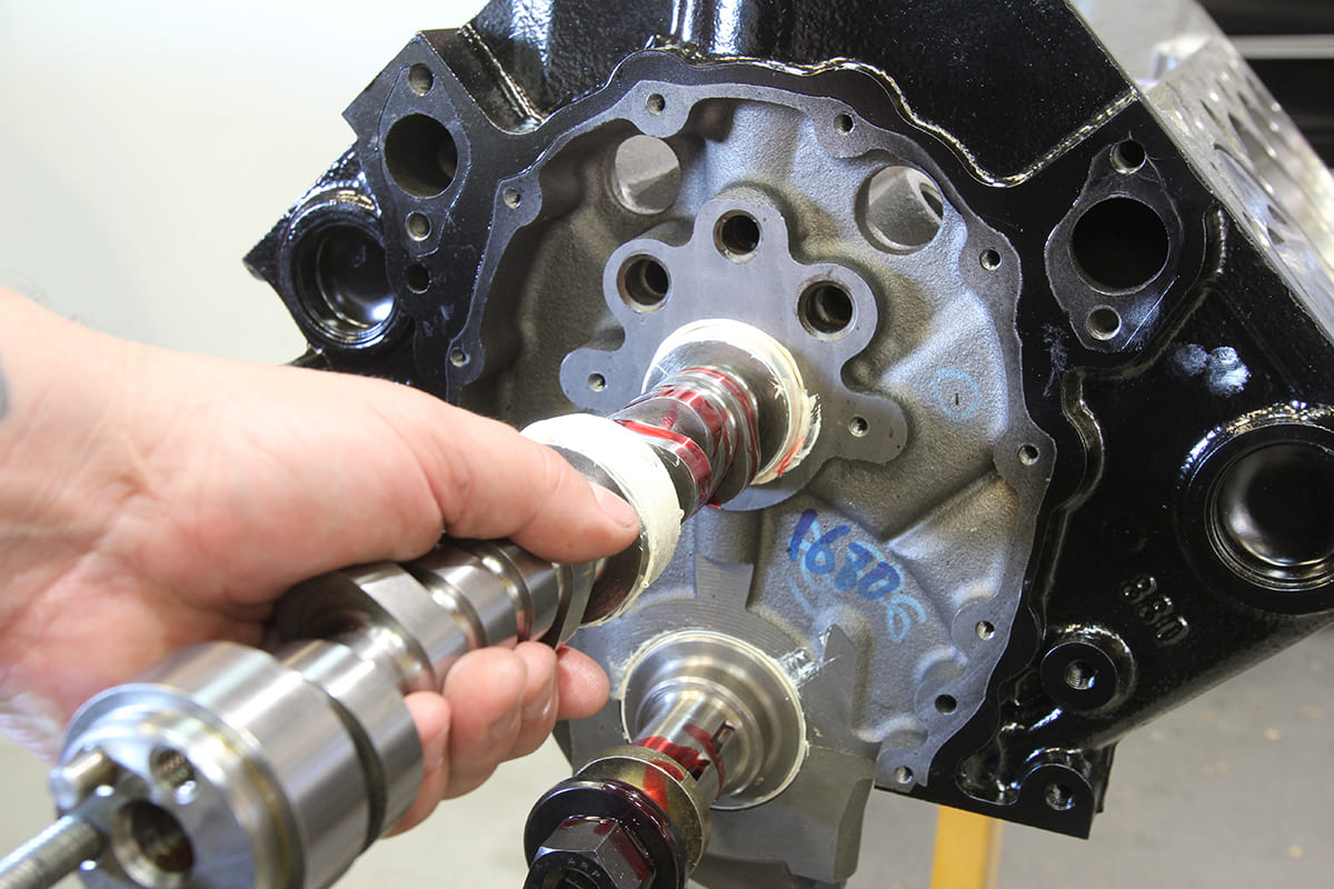
When it comes to installing a camshaft, the operation is pretty straightforward: lube the lobes, slide it in the block, and install the timing chain set. But for those gearheads who might want to adjust the timing of the cam for a little more low-end grunt or to move the powerband up a few hundred rpm, there’s more to the simple stab-and-go approach. And even if you find yourselves, like us, not chasing that little bit of extra power but like the idea of double-checking that everything is as advertised, there lies more to a camshaft install than one might realize. This extra step is commonly known as “degreeing” the camshaft.

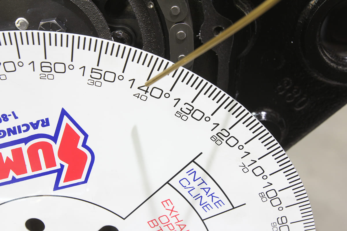
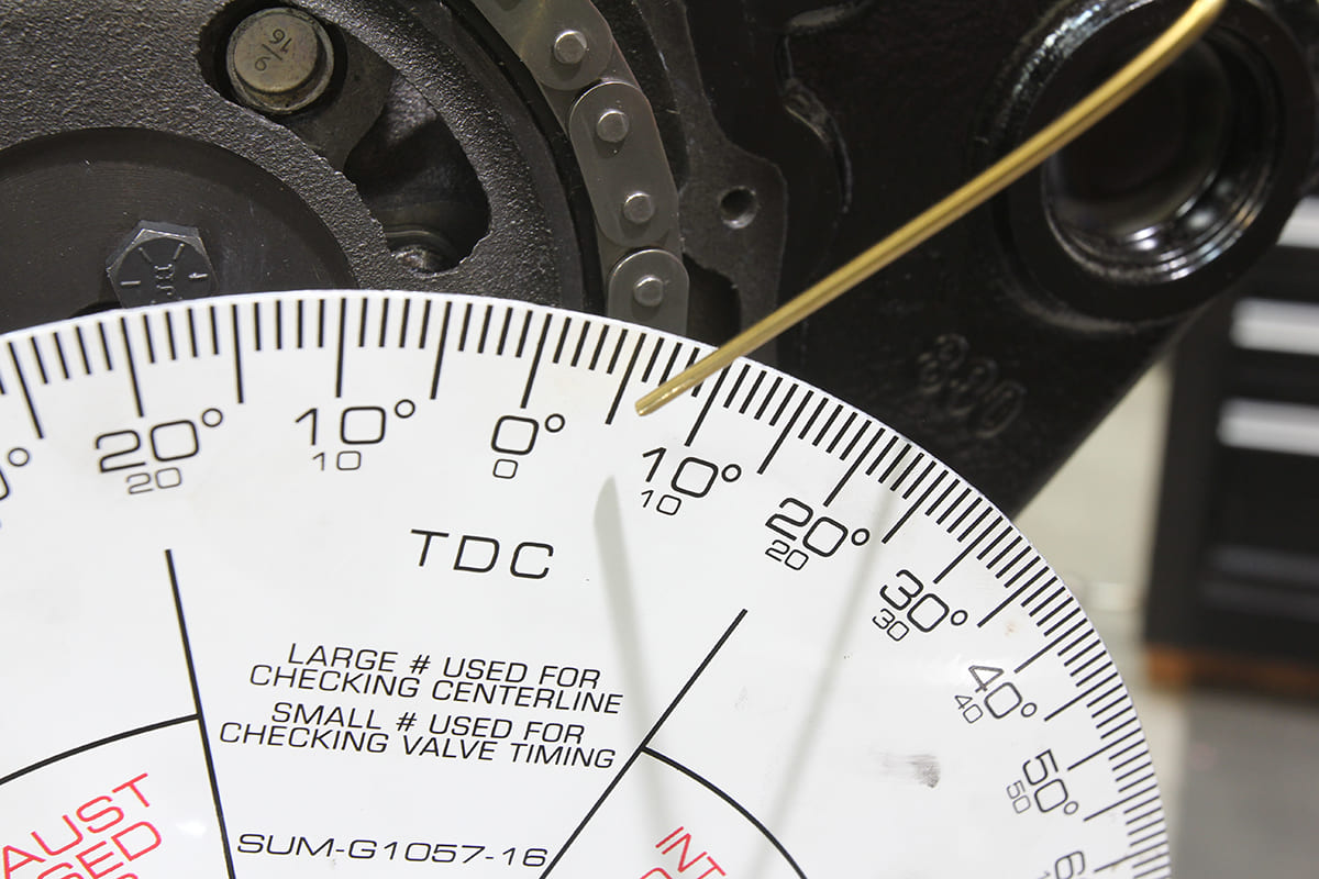
In layman’s terms, degreeing a camshaft is the simple operation of checking that the installed camshaft functions happen as specified on the cam card. Each and every camshaft is ground to achieve a certain event at a certain moment, so it’s important to ensure that those events happen when they’re supposed to after the camshaft and timing chain set are installed. This easy operation ensures that not only has the camshaft been manufactured according to the cam card’s specs, but also ensures that the engine builder didn’t make a mistake—a mistake that could possibly take out expensive components if installed incorrectly. By comparing the results from degreeing the camshaft with the cam card, we can verify that the valves will open and close when they’re supposed to and the lift and duration is as advertised.

Once the camshaft is installed, we will turn our attention to the cylinder heads. But first we want to verify that our static compression ratio is going to be within the recommended specs for a street car, that is, under 10:1 for pump gas. We ran the numbers when we originally chose the components, but it’s always a good idea to double-check it as the engine goes together. There are things that are unknown until the pistons are in their place (deck clearance) and things that can vary (head gasket thickness), so it’s a good idea to use a product such as Summit Racing’s Compression Calculator to crunch the numbers and make sure we’re still in the green before it’s too late.
With those items left to cover this month, we’re going to put off the installation of the cylinder heads and leave the installation and adjustment of the valvetrain for next month, concentrating instead on the installation and inspection of the camshaft and to double-check our compression ratio to ensure we’re good to go next time.
ACP
Cylinder Head Calculations
When it comes to building an engine from one-off parts, one of the most common questions that comes up is, “How do I determine the final compression ratio?” Unfortunately, this can be difficult to calculate without at least a few parts on hand, or at least their specifications. The first question that needs to be asked is whether the engine will be naturally aspirated or forced induction. From there, a static compression ratio should be chosen based on use, fuel availability, and so on. For a naturally aspirated street-driven car using a mid-grade (pump gas) 91-octane fuel, that ratio will most likely be between 9-10:1. Anything higher and detonation, overheating, or any other myriad of issues can arise. With that in mind, it’s a simple manner of choosing the right components to yield a static compression ratio that will result in an engine that will be responsive and fuel efficient.
Determining the static compression ratio of an engine can be a daunting task for those of us who slept through math class, thankfully Summit Racing has a Compression Calculator (summitracing.com/newsandevents/calcsandtools/compression-calculator) that will spit out the number we’re looking for by simply feeding it information provided by our component manufacturers, combined with a few measurements taken from our engine.

Inputting the info Summit’s Compression Calculator needs is pretty straightforward at first. Bore diameter and stroke measurements should be straightforward. Even if the engine block has yet to be machined, one only need guess on the high side; say 4.010-inch as opposed to an even 4-inch bore as it only bumps the number a few tenths of a point. The number of cylinders are obviously set in stone. Cylinder head volume, however, is one of the variables that can vary that static compression number the most. For example, using the same engine components, a cylinder head with a 60cc combustion chamber volume yields a static compression ratio of 10.87:1, whereas a head with a 72cc combustion chamber drops that number to 9.56:1. The next number (Effective Dome Volume) can throw a wrench even further into the works. For our engine build, we’re using a relatively modest piston, with a flat top and an Effective Dome Volume of 5 cc. Using the same 60/72cc head options but changing the Effective Dome Volume by installing a set of pistons with a -4cc dome, and those numbers jump to 12.16:1 and 10.51:1, respectively. You can see that even with the larger combustion chamber heads, the static compression ratio is higher than our preferred 9-10:1. Compressed Gasket Thickness is the last variable in our compression ratio calculation that can be changed by simply swapping one set of gaskets for another. The smaller the number, the higher the compression ratio, so it’s good to run through these calculations ahead of time to be sure the components all work together.
These numbers can result in a fairly accurate static compression ratio, at least to the point of picking components, but the story doesn’t end here.
Until now, we’ve been able to punch in numbers provided by parts manufacturers that shouldn’t vary from build to build. These numbers are essentially “set in stone,” but when it comes to deck clearance the only way to determine that is by measuring the actual pistons installed in the engine block.
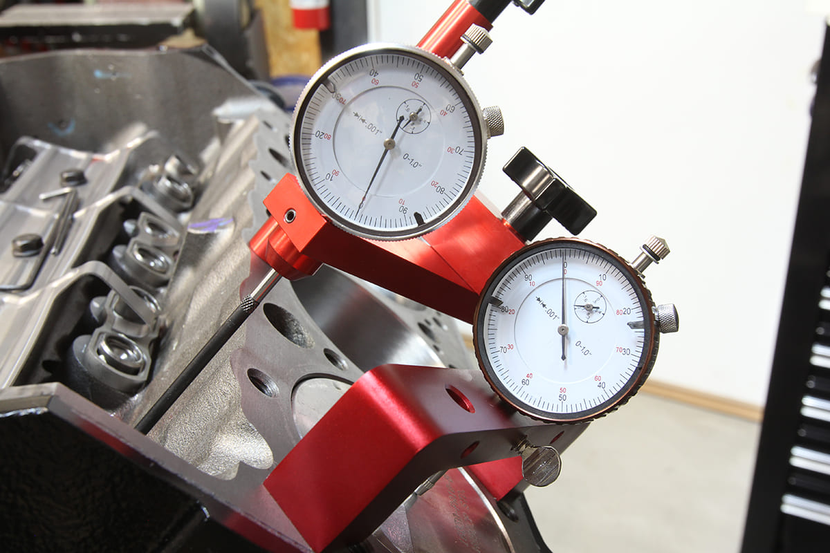
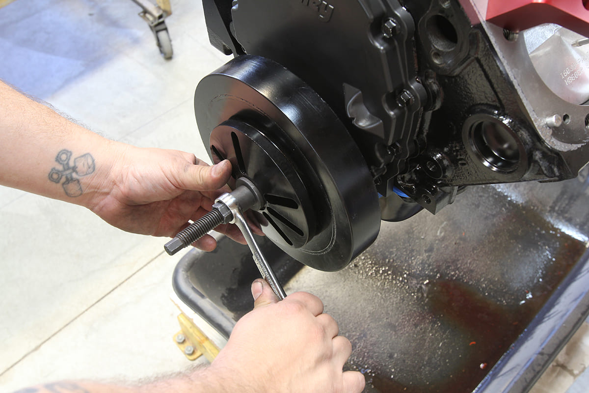
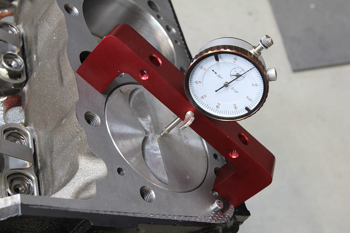
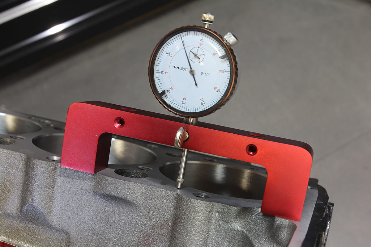 To determine Deck Clearance, once again we’re using Summit’s Camshaft Checking Fixture with a dial indicator installed and “zero’d” to the cylinder head deck on the block.

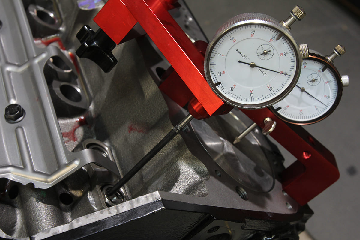
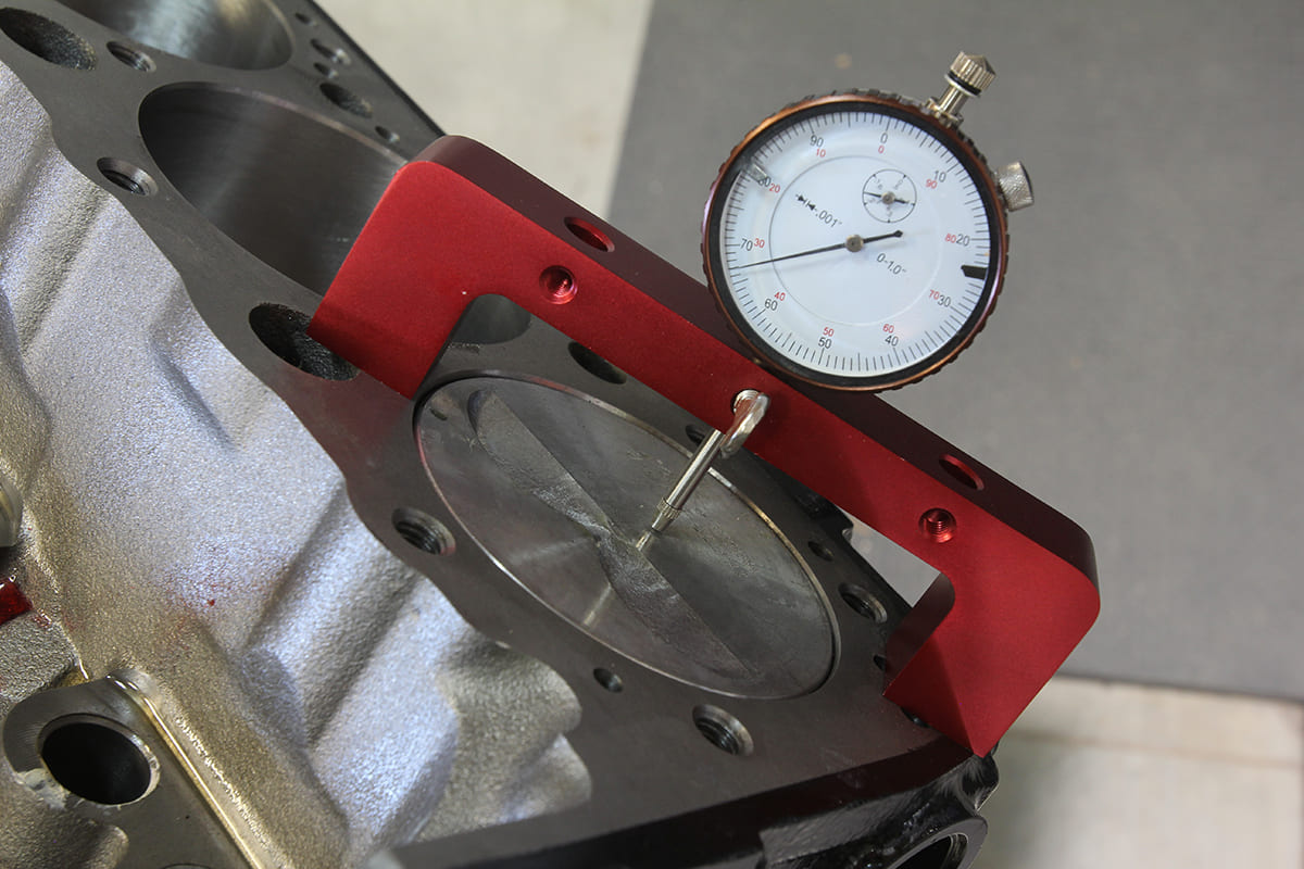 The number one cylinder is then brought to TDC with the fixture mounted over the center of the cylinder bore and the difference noted. In our case, that number is 0.033 inch.
 With that number determined, we can complete the fields in the Compression Calculator and find that the static compression ratio for our engine (9.88:1) is exactly where we want it.
Sources:
Clampdown Competition
clampdowncomp.com
Cotati Speed Shop
(707) 586-8696
cotatispeedshop.com
Summit Racing
(800) 230-3030
summitracing.com