

A Handful of Helpful EFI Techniques
By Jeff Smith – Photography by the Author
Bob Dylan once wrote “… the times they are a-changin’.” He probably didn’t have electronic fuel injection in mind when he wrote those words, but it is certainly true that there’s been a rich mixture of changes with aftermarket electronic fuel injection in the last 10 to 15 years. It wasn’t all that long ago that most car guys steered clear of electronic control over fuel and spark but with a tremendous variety of high-quality systems on the market and the opportunities they offer have made believers out of at least a few serious doubters.
But we have to admit that this conversion to electronic control has not been easy. There has also been a smattering of challenges to make these systems operate smoothly. It doesn’t take much effort to find negative comments about every system out there. While it’s easy to blame the manufacturers, our experience with many of these systems is that there are often simple solutions to many of these difficulties. We’re not going to blow smoke in your face and claim that all these systems work flawlessly. That’s just not true.
However, we will stand firm on the belief that many of these systems will operate well and offer respectable returns on the investment as long as certain rules are followed and an effort to undo these difficulties is attempted. In our experience, it’s often simple installation errors or an occasional failed sensor that is to blame. But if you follow the instructions—yes you must read the instructions carefully—likely you can avoid many of the pitfalls that plague those installers who just don’t make the effort to do the job correctly.

One point that must be highlighted is that fuel injection is not a cure-all for an ailing engine. If the engine is not running properly with a carburetor, this could be an indication of either internal engine problems or ignition issues that will not be solved by adding EFI.
As an example, we’ve experienced an off-idle hesitation in a small-block, four-speed Chevelle that continued to plague the car after testing two different EFI systems. The problem turned out to be bad hydraulic roller lifters that easily bled down, causing the hesitation and poor performance. As you might expect, the EFI system did nothing to clear up this issue. The fix was a set of high-quality hydraulic roller lifters that immediately improved performance across the entire engine rpm range from idle to 6,000 rpm. No amount of fuel or spark tuning would have solved this mechanical issue.
We won’t be able to address all the tuning issues with a baker’s dozen collection of tech tips, but what we can do is offer these recommendations for ways to diagnose your particular issue. One way to work through the diagnostics is by eliminating the simplest things first. For example, we had a problem with an aftermarket EFI that was finally diagnosed as a poor electrical ground. The repair literally cost pennies. The point is to try the easiest and least expensive fixes first before you dive into the more complex issues. It’s crushing to find out that an off-idle hesitation is because the car was just low on fuel. It sounds silly but that’s happened—and probably more than once.
Take a walk through these EFI troubleshooting suggestions and perhaps there may be one or two techniques that will apply to your specific issue. Remember that EFI is a basic binary decision-making system. Based on sensor inputs, the computer will only execute what it’s been programmed to do. Our job is to make sure it’s making the right decisions all the time.

Sources
Aeromotive
(913) 647-7300
aeromotiveinc.com
FiTech
(951) 340-2624
fitechefi.com
Granatelli Motorsports
(805) 486-6644
granatellimotorsports.com
Holley
(866) 464-6553
holley.com
OPTIMA Batteries
optimabatteries.com
PerTronix
(909) 599-5955
pertronixbrands.com
If there is one over-riding issue that afflicts aftermarket EFI systems it’s the common issue of neglecting electrical grounds. Our source for much of this story, Andy Starr of Holley’s EFI department, notes that this is a very common situation that customers often struggle with on a newly -installed system that is under-performing. AndyStarr saysid, “The days of claiming ‘Hey this worked okayOK with my carburetor’ mentality are over.” The ideal situation for any EFI system is to connect the main power and ground leads directly to the battery. The battery then acts like a giant electrical shock absorber to minimize electrical noise.
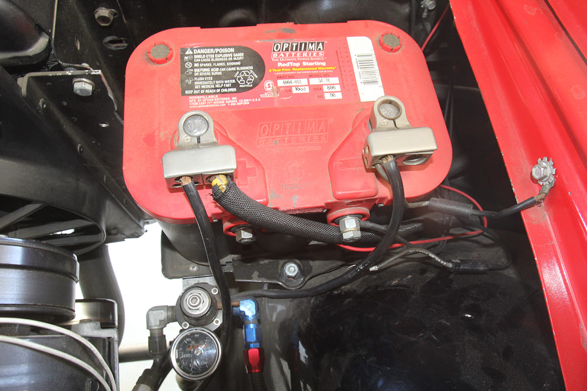
The ideal approach is to ensure that not only the engine but also the body is properly grounded to the battery. All electrical circuits will only perform properly when the entire circuit from the battery to the load and then through the ground return have minimized resistance. Along these lines, seven heavy-duty power leads all running to the positive battery post is not only clumsy but just looks nasty. One way to clean this up is to use a Group 75/86- or 34/78-style battery like this Optima that features both traditional top posts for the starter motor but also side posts that allow the installer to connect individual power to the EFI. This offers a clean solution that works great and minimizes clutter.
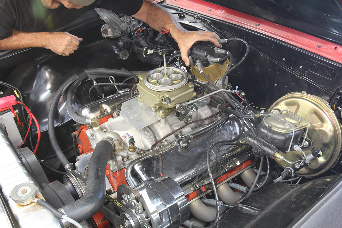
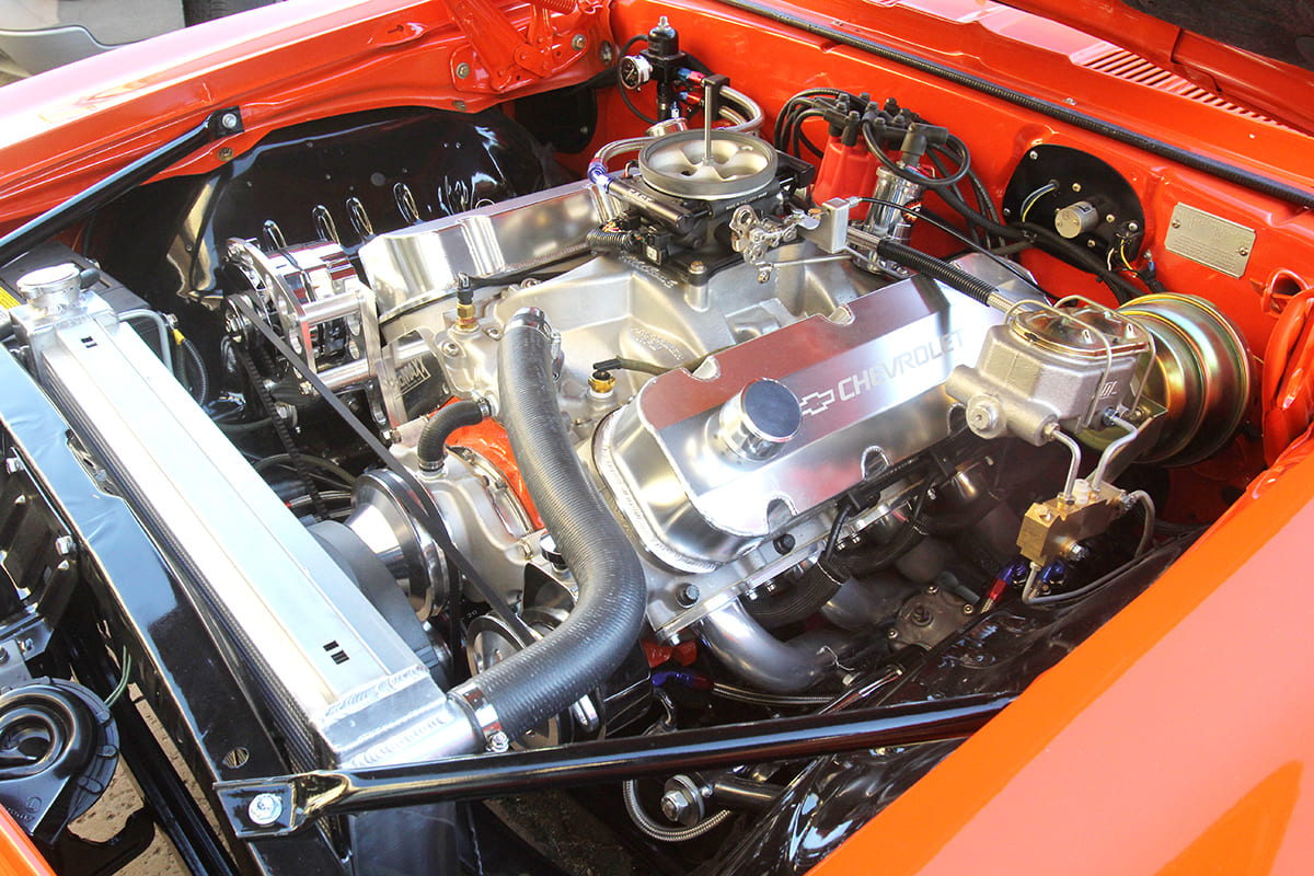
It’s always a good idea when installing a TBI-style EFI system for the first time to control just the fuel side of a throttle body system. As an example, when we first converted this big-block El Camino with a Sniper throttle body, Holley suggests to convert the fuel side first and leave the existing ignition system in place. This reduces the number of errors thatn can occur during installation and early tuning. Once the fuel side is optimized and the engine is running well, then you can convert to electronic ignition control. This way, once you create a decent ignition curve, you can then optimize the entire package. Holley offers an opportunity to connect the Sniper to a laptop in order to do more finite tuning. This allowed us to optimize the ignition curve and improve driveability and even improve the fuel mileage slightly.
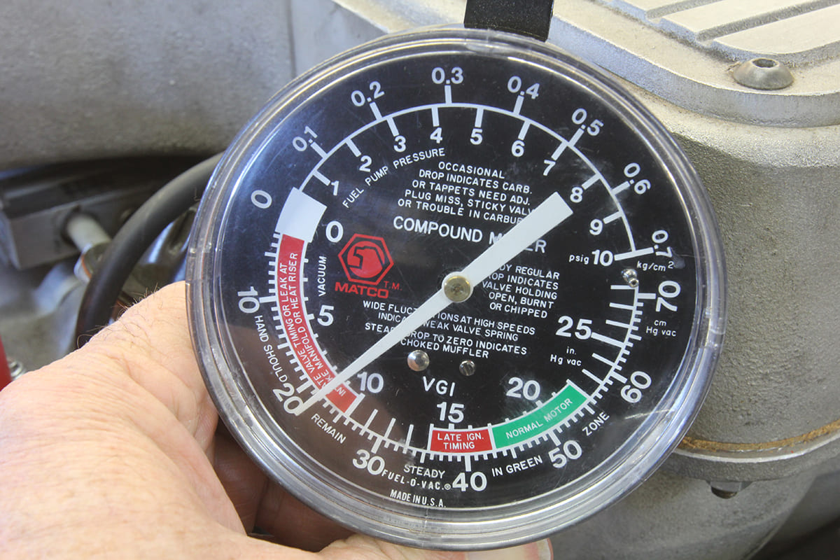
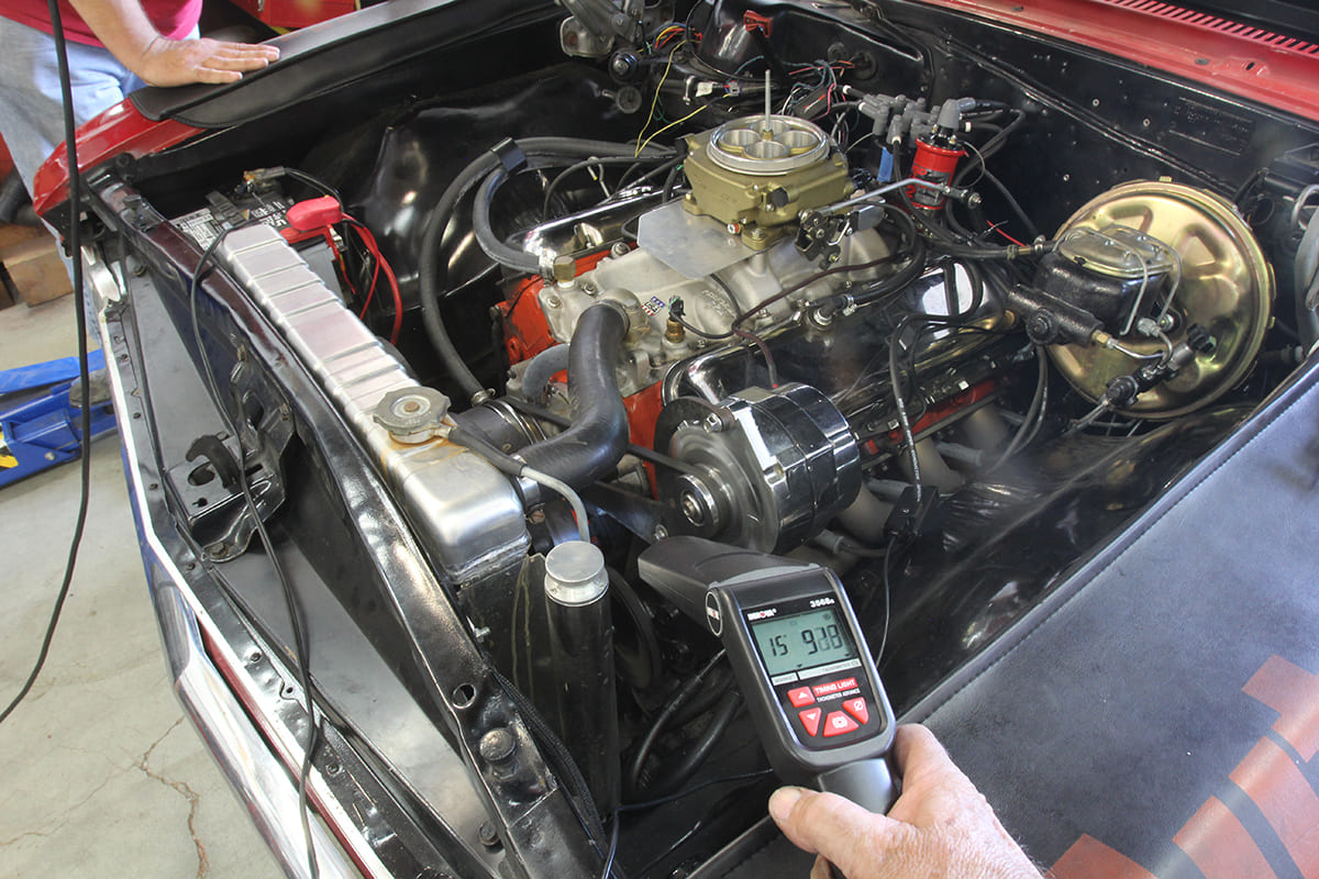
TBI-style throttle bodies generally do not work well with engines that idle with manifold vacuum levels below 10 inches of mercury (“Hg) (inside scale on the gauge in the photo). These TBI systems can be made to work on the street but generally have to be tuned very rich to compensate for internal EGR in the intake manifold caused by valve overlap. One way to mitigate this is to compensate by adding initial timing (which we go into more detail in the next tip).
With throttle body–-style EFI, if the engine idles decently but stumbles slightly off idle, try adjusting the idle and / or cruise air/-fuel ratio slightly richer. This can help overcome an off-idle stumble. This assumes that the ignition system has sufficient initial timing. An off-idle stumble can sometimes be cured with more initial timing. Some enthusiasts feel that 10 -degrees initial is a maximum, but the reality is that performance engines with even a mild cam often prefer 14- to 16- degrees initial timing (and perhaps more) with a curve that quickly initiates after roughly 1,500 rpm.
Each engine will be different, so before blaming the EFI for an engine that is not responsive directly off idle, it’s best to experiment with different initial timing adjustments to see if that may help create a smooth transition from idle to part throttle. Each engine combination will be slightly different and some engines may want more timing and others less. That’s why tuning after the installation is so important to the final combination. Of course, ported vacuum advance once the throttle is opened will also assist in this effort.
No self-learning EFI system will ever run properly if there is any kind of leak in the exhaust side where the O2 sensor is located. This sets up a serious problem, so let’s go though why this occurs.
Self-learning fuel- injection systems use the oxygen sensor as the main feedback device for evaluating how much fuel to give the engine at any operating point. This means if the oxygen sensor reading is in error, the whole system can go terribly bad. Let’s start by describing how an oxygen sensor works.
These sensors generate input into the ECU reported as an air/-fuel ratio but how they really operate is by measuring the amount of free oxygen in the exhaust. This amount of oxygen is then used to compute the air/-fuel ratio. If there in a leak in the exhaust (which often is not audible as a “tick”) there is fresh air being drawn into the exhaust. The oxygen sensor picks up on this oxygen and interprets this to mean the engine is running lean. The result is additional fuel delivered to the engine.
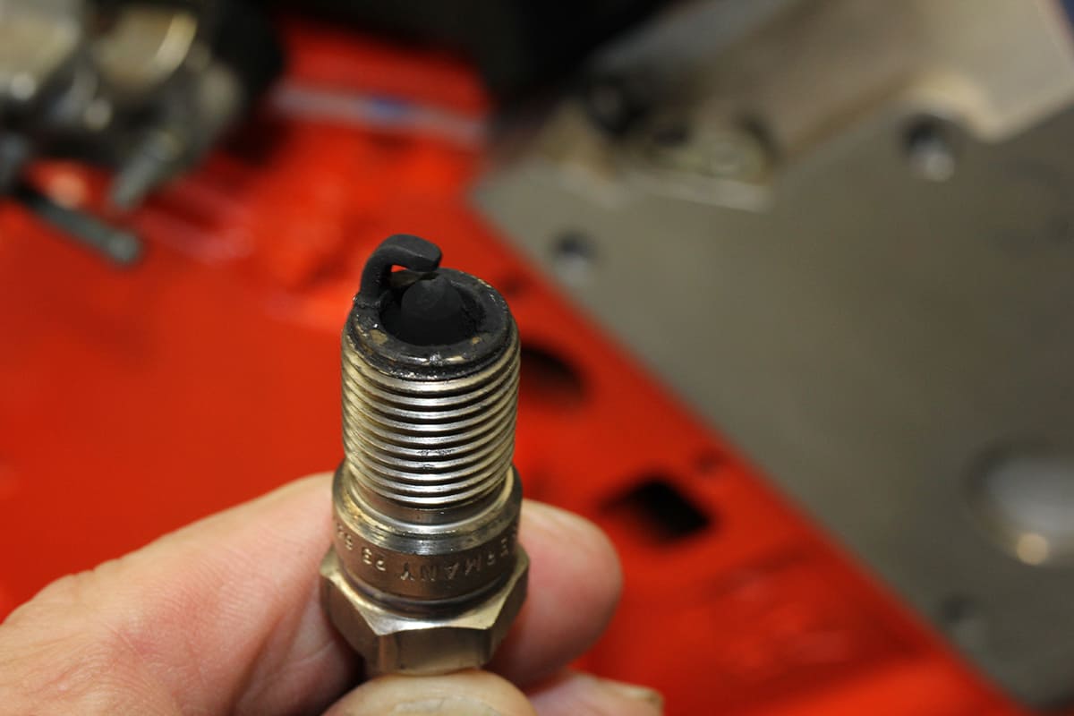
Each time the engine moves into normal operating temperature, the self-learning system reads the data from the oxygen sensor and then uses it to adjust the air/-fuel ratio. When the engine is shut down, this learned change (in this case – the engine is running too lean) will be added to the system’s long-term memory. Unfortunately, if the engine has an exhaust leak, the next time you start the engine, it is now running with more fuel than before but the exhaust leak is again detected and reported as a too-lean condition. After this cycle is repeated four or five times, the engine is now running excessively rich and yet the sensor continues to report that the air/-fuel mixture is lean. You can see now why the engine will quickly run way too rich and the owner will be very disappointed.
The only way to prevent this situation is to ensure that the exhaust system is leak-free. We had experience with a friend’s highly modified small-block Ford that suffered from this exact condition. The car owner was convinced beyond a doubt that there was no leak. Yet a careful examination of the headers on the same side of the dual exhaust where the oxygen sensor was located revealed major cracks in two header tubes that were contributing fresh air into the exhaust. This caused his engine to run excessively rich. These leaks can come from header gaskets at the head or the collector, poor-sealing iron manifolds, leaking fittings, or as in the case of the small-block Ford, from cracked header tubes.
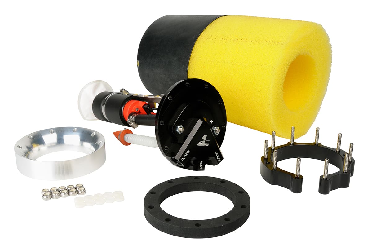
Many EFI driveability problems can be traced to a poor fuel delivery system. All EFI systems require consistent fuel pressure where the fuel pump pickup is always submerged in fuel. Several companies offer in-tank fuel pump conversions, such as Aeromotive’s Phantom system and Holley’s Sniper tanks. This next tip is ultra-critical— – the most important point in any fuel delivery system is the inlet to the pump. When the pump is located in the tank it is usually submerged in fuel and the weight of the fuel in the tank helps push fuel into the pump inlet. When the pump is located outside the tank and above the fuel level, this requires the pump to work extremely hard to pull fuel up from the tank. Pumps work better at pushing fuel but do not excel at pulling fuel. The higher or farther away the pump is from the fuel tank, the harder it has to work, which will cause cavitation— – a condition that should be avoided at all cost.
Always locate the pump at fuel level or below so that hydrostatic pressure from the fuel itself will assist in pushing fuel into the pump inlet. Starr also pointed out that it’s critical to minimize the number of 90-degree fittings on the suction side, make sure the inlet line to the pump is of sufficient size, and to also ensure the tank is properly vented. These points cannot be overstated.
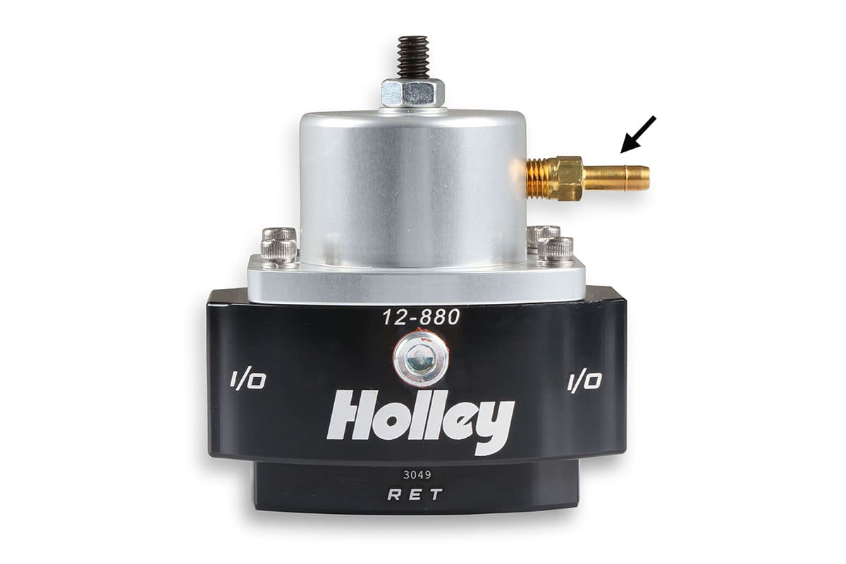
When using a throttle body EFI where the injectors are located above the throttle plate, the general recommendation is to leave the fuel pressure regulator open to atmospheric pressure. This means do not hook the regulator to manifold vacuum. Conversely, if the injectors are placed below the throttle blades, then hook the vacuum nipple on the pressure regulator up to manifold vacuum.
This might sound confusing so let’s go over why. With a multipoint EFI, the injectors are located in the manifold and are subjected to manifold vacuum at idle. This means there is a greater pressure difference across the injector than it would be if the injectors were located above the throttle blades. To maintain the same pressure across the injector, most multipoint EFI systems reference the pressure regulator to manifold vacuum. This will reduce line pressure at idle. As an example, if the engine is idling at 16 inches of mercury (“Hg) manifold vacuum, that’s equivalent to almost 8 psi of negative pressure. The net result is that if the pressure regulator is not vacuum-referenced, it’s like the line pressure increased by 8 psi. On a 43-psi system, that’s an 18 -percent bump in pressure. But by vacuum referencing the pressure remains at the net of 43 psi.
As an additional point, FiTech recently altered its recommendation and suggests that its throttle body system (injectors above the throttle blades) can benefit from connecting manifold vacuum to the fuel pressure regulator. This appears to be an attempt to manage idle and part throttle fuel by reducing the fuel pressure. Now that you understand why these systems operate the way they do, you can make your own decisions or at least try this on your throttle body system and see how it responds. But with multi-point EFI, the recommendation would still be to connect the pressure regulator to manifold vacuum.
The correct procedure for setting fuel pressure with a vacuum-reference system is to allow the engine to idle and disconnect the vacuum line from the pressure regulator. Connect a fuel pressure gauge to the system and set the pressure to the manufacturer’s spec in the instructions. Once that is set, then reconnect the vacuum line to the pressure regulator and it will balance the fuel pressure to the manifold vacuum.
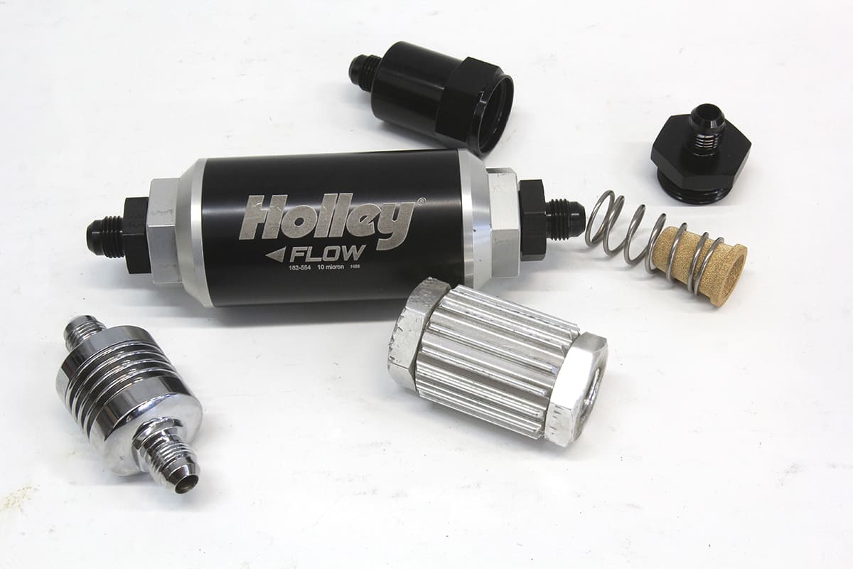
A classic mistake we see all the time is where the installer incorrectly places the very restrictive 10-micron filter on the inlet side of the fuel pump. The correct position is to place the 100-micron filter between the pickup and the pump and then the 10-micron (or 40 sometimes) on the high-pressure side of the pump.
All EFI systems need large fuel filters with sufficient surface area to trap dirt and yet not restrict volume. An undersized or partially plugged fuel filter is a classic EFI installation mistake. An under-sized filter will allow part- throttle operation but fuel pressure will drop at WOT and run very lean— – perhaps surge under power. All EFI systems need a large fuel filter to trap dirt and yet not reduce volume.
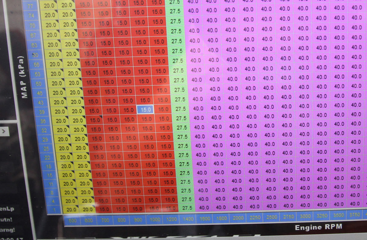
Some TBI systems like the revised MSD Atomic and the Holley Sniper (among others) allow you to access and expand upon the idle, cruise, and WOT AFR and ignition timing settings with access into the actual fuel and spark maps. If you are looking at perhaps buying a throttle body EFI system, look for any system that allows access to expanded tuning parameters using a laptop. The basic systems enter data with the handheld, – such as idle, cruise, and WOT air/-fuel ratios. If you could view these entries on a full fuel tuning map, you’d see that these simple inputs make radical jumps in air/-fuel ratios and ignition timing in literally 100-rpm increments. While these truncated inputs work, it is a somewhat crude way to tune either air/-fuel ratio or ignition timing. The photo shows an example of a spark map. Note how the timing jumps from 15 to 27.5 to 40 degrees literally in three small rpm points between 1,200 and 1,500 rpm. That represents a total change in engine speed of only 300 rpm. We ran the engine on the street with these settings and it ran acceptably, but we felt it could be much better. By using a laptop to access this screen, it’s a simple process to blend the timing curve into a more gradual shift in timing and AFR that will allow the engine to run smoother and more efficiently.
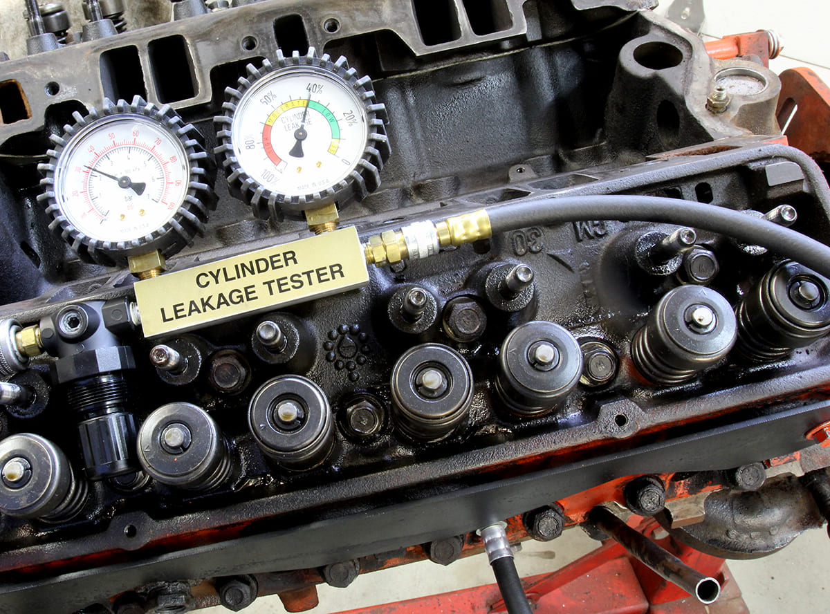
It should go without saying that anytime you are attempting to fine-tune an EFI-equipped engine, that the engine needs to be in excellent mechanical condition. We ran into a persistent driveability problem that was finally solved when the set of cheap, hydraulic roller lifters that easily pumped down were replaced with quality hydraulic lifters. The engine immediately responded with improved throttle response and better power because all the valves were working together and opening and closing at the appropriate time. The engine in the photo shows a leak down percentage of 40 percent. The engine ran, just not very well. This illustrates the point that EFI could be blamed for poor performance when the real culprit was an internal mechanical problem.
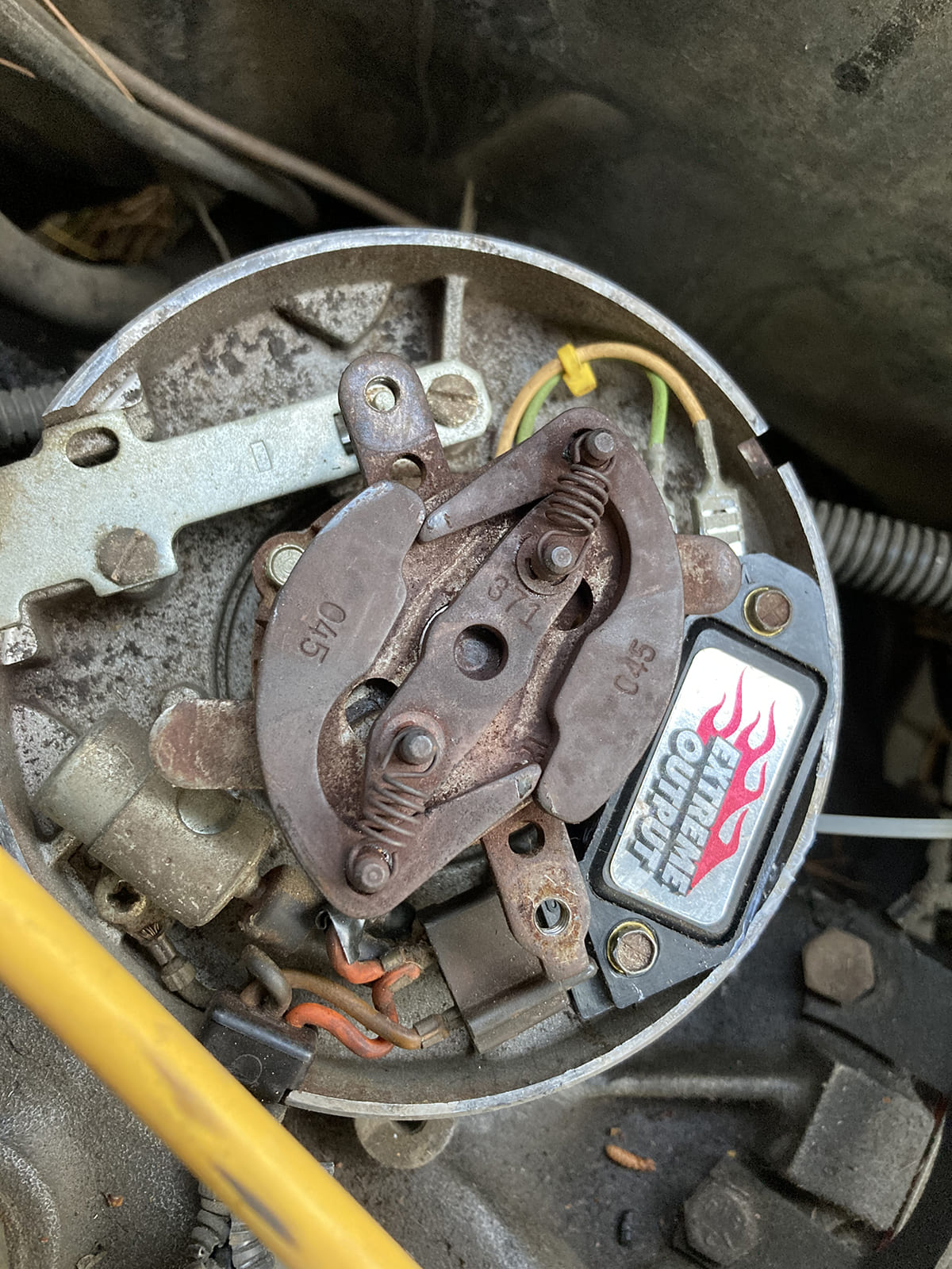
Many poor performance issues that point the finger at EFI can often be traced to the ignition system. We’ve seen HEI distributors with frozen advance curves— – rusted by internal sparks shorting through the plastic rotor and grounding through the advance weights and springs. We even ran into a unique situation where a persistent part -throttle hesitation was caused by severe backlash between a worn distributor gear and the camshaft gear. This occurred because this small-block Chevy crate engine employed a steel hydraulic roller cam but was combined with an iron distributor gear. This produced severe wear in the distributor gear that caused excessive backlash. Under light acceleration, we witnessed the ignition timing actually retard 13 degrees and then immediately advance. The timing retard caused the hesitation, not the EFI system. This was repaired by using a melonized gear on the distributor.
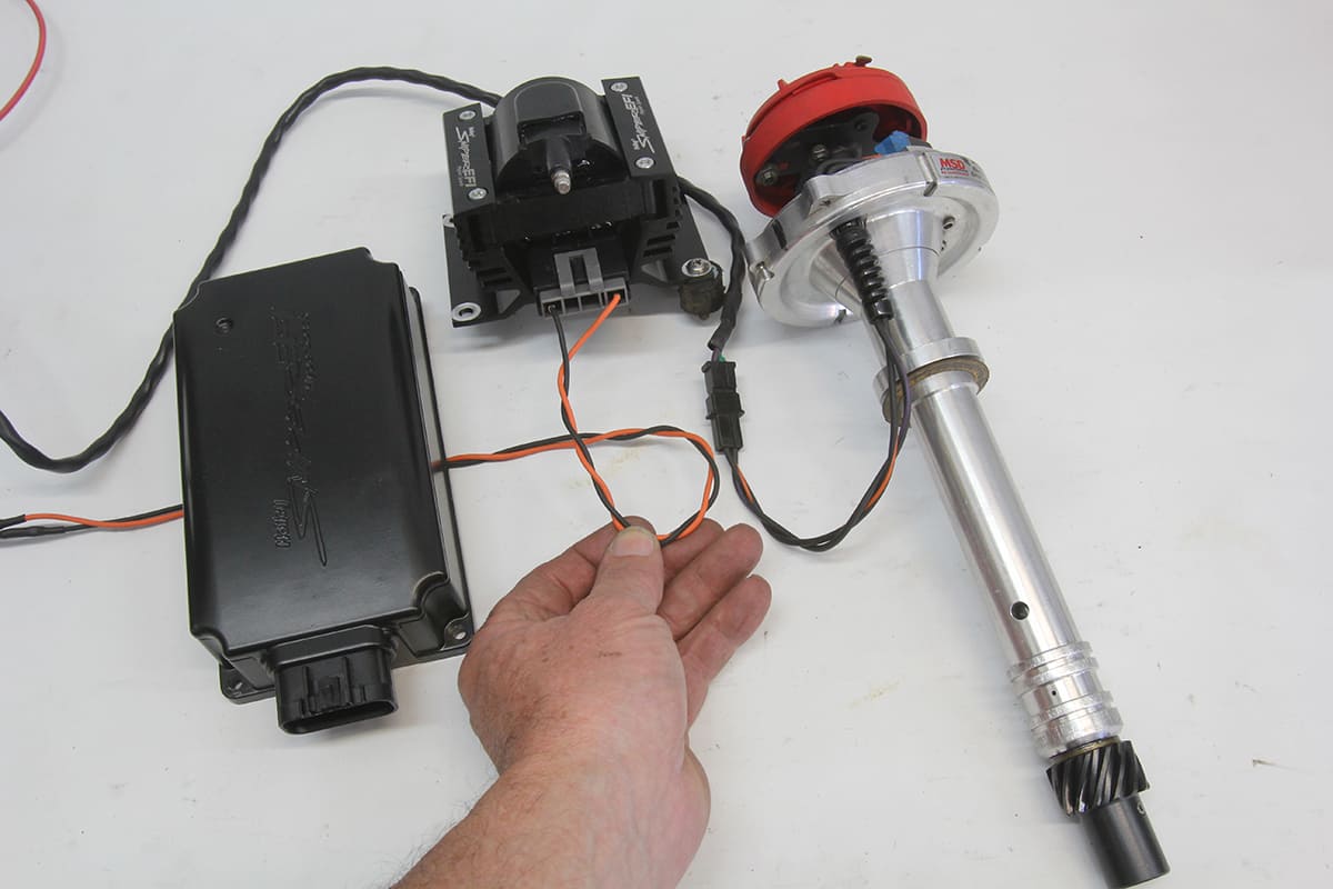
Capacitive discharge (CD) ignition systems can cause havoc with EFI systems if not properly insulated and grounded. CD systems operate by charging the primary ignition side of the coil with 550 voltsV from a capacitor inside the CD box. This 550V-volt charge can cause radio frequency interference (RFI) that can actually incapacitate an EFI system if the primary charge wires are not properly shielded. This situation is made even worse when the CD box is located some distance from the coil. This lengthens the wire path from the CD box to the coil and creates an excellent antenna from which to radiate RFI. This situation is much the same effect as that created by those 300-foot- tall antennas used by broadcast radio stations. The longer primary coil wires frorm the CD box act like a big antenna. This creates a situation where the farther the CD box is from the ignition coil, the more RFI noise it will generate.
One remedy is to twist the wires that lead from the CD box to the coil. This will help reduce the energy field around these wires and minimize ignition noise. Another important tip is to not run the wires triggering the coil parallel to the sensor wires from the ECU. This often happens when an installer is looking to create a visually clean installation. Separating these wires as much as possible will certainly help. High-quality spark plug wires like those from MSD, Granatelli, PerTronix, and other manufacturers will also help.
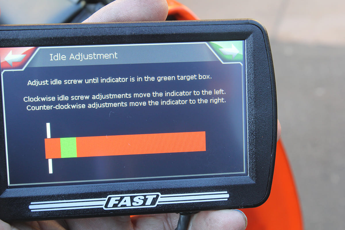
A stumble or a “hanging throttle” on deceleration can be caused by an improperly set idle air-control (IAC) motor position. We’ll take the example of the FiTech throttle body as our example since we’ve seen this quite often in these systems. FiTech (and most other throttle body systems) references its IAC position as a percentage and recommends a position of 3 to 10 percent. If the number is near zero, and the idle speed is not where you’ve commanded it, then this generally means the throttle plate at idle is opened too far and the idle airspeed motor is closed in an attempt to bring the idle speed into spec.
The more common occurrence is that the IAC is open much farther at idle than the 3 to-10- percent range. We often see these IAC numbers at 35 percent or higher. This requires the tuner to open the throttle blade as you would to increase idle speed on a carburetor. This opens the throttle blade and allows more air into the engine. The computer will read the increased rpm and command the IAC to close in order to achieve the commanded idle speed. A couple of adjustments may be necessary to sneak up on this 3 to 10 number.
Of course, anytime the curb idle position is altered on any EFI system, this requires the user to recalibrate the throttle position sensor (TPS). Failure to do this will cause other drievability problems so do not overlook this important step. The best procedure is to optimize the IAS position first, then go back and re-adjust or re-set TPS.