By Jeff Smith – Images by the Author
So much of life is about being at the right place at the right time. The same is also true about ignition timing for internal combustion engines. For an engine to make great power it must have all the right parts, including camshaft, cylinder heads, compression, induction, and exhaust. But if the ignition timing is too late or too early, the engine will run poorly and there’s the potential for catastrophic damage.
There is also the time-honored tuner’s advice that we’ve seen played out a hundred times that proclaims, “Ninety percent of carburetion problems are ignition related.” That may be overstating the case slightly, but it’s true enough to take to heart.
This story will outline the three components of ignition timing for engines with distributors and how they all interrelate to bring out all the potential power and efficiency your engine has to offer. We will focus on street engines with carburetors and distributors with an abbreviated nod toward fuel-injected engines with computer control of the ignition. The approaches to obtaining the right ignition curve are the same for all engines—EFI just gets there using a much more precise digital approach.

For engines with a distributor, there are three components to the overall ignition curve. The first is initial timing followed by mechanical advance, which is further enhanced at part throttle with vacuum advance. Let’s define each of these and then dive into how all three interact to optimize performance.
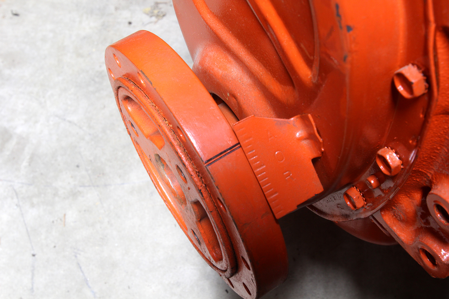
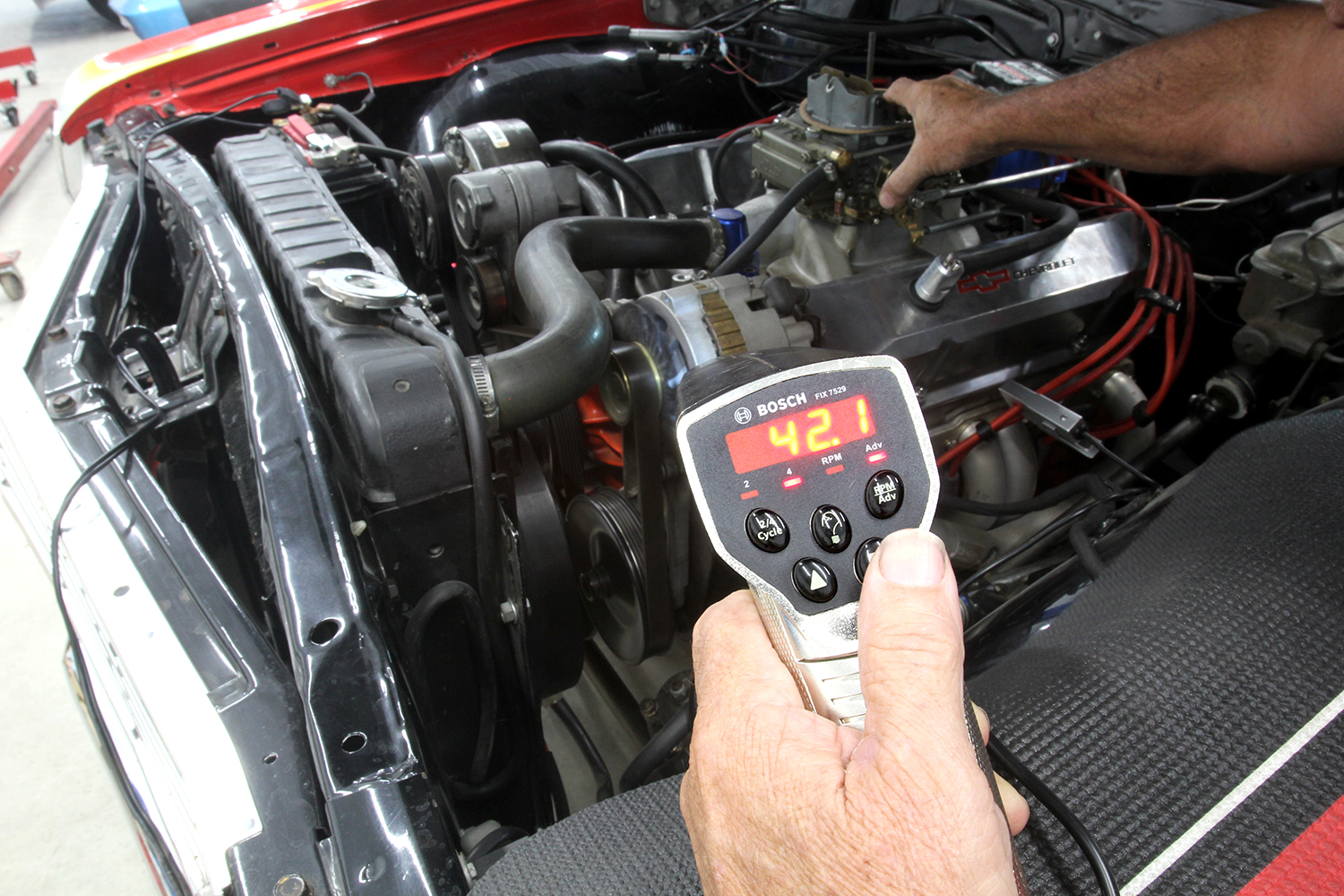
Initial timing is the number of degrees of ignition timing before top dead center (BTDC) that is set by rotating the distributor body and verified with a timing light. While OE carbureted engines from the 1960s and 1970s tended to apply conservative single-digit initial timing numbers like 6 degrees BTDC (and sometimes less), most modern performance street engines run best with initial numbers of 10 to15 degrees. We’ll get into more details in a moment.
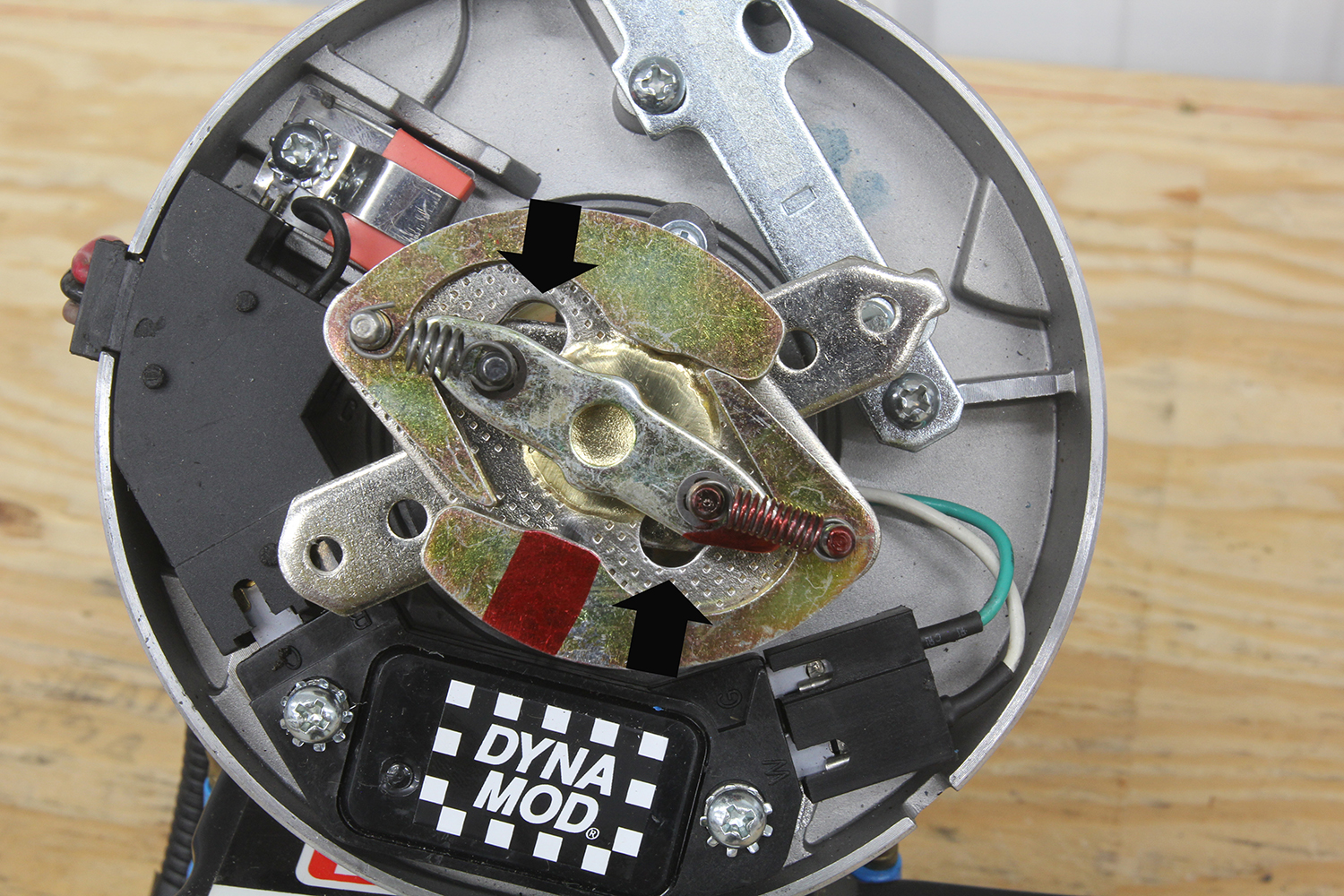
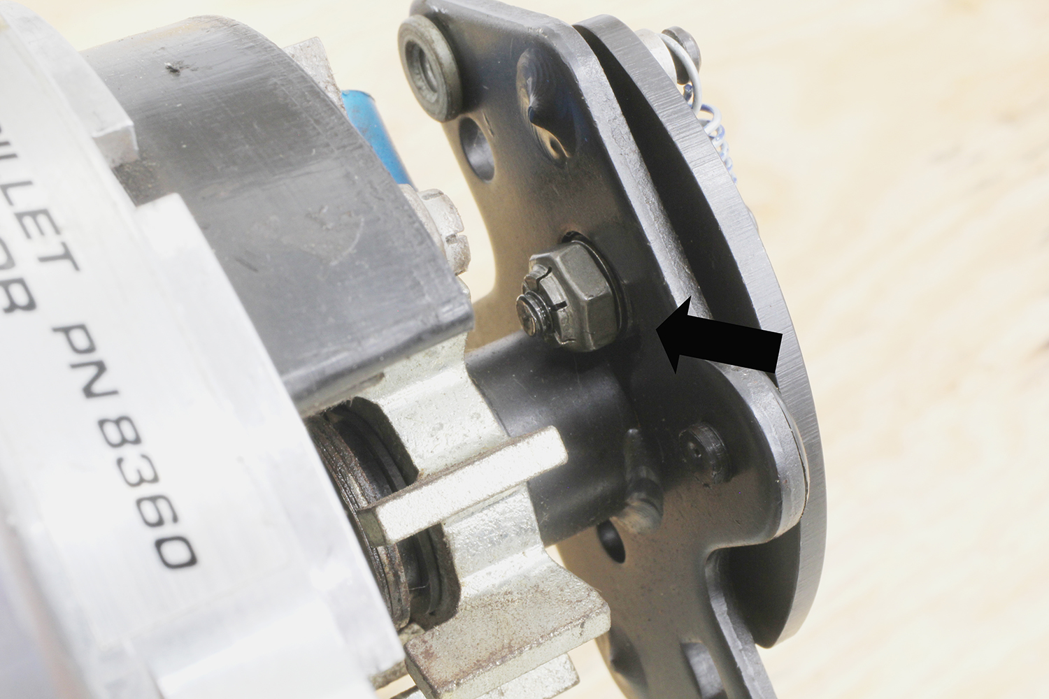
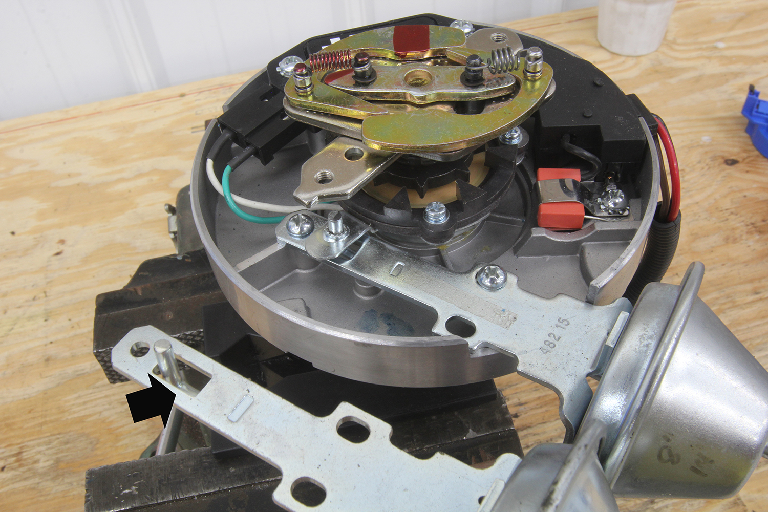
The second component of ignition timing is mechanical advance. This is the amount of advance produced by the distributor using a set of weights and springs that rely on distributor rpm to add advance. This system uses centrifugal weights and springs to create an ignition curve. A typical performance mechanical advance curve will begin around 1,500 rpm and be completed between 2,500 and 3,000 rpm. The rate of mechanical advance can be altered by changing the strength of the springs. As engine speed increases from idle, centrifugal force forces the weights outward at a rate determined by the stiffness of the springs. Heavy springs delay the rate of advance while lighter springs allow the weights to swing outward at a lower rpm, adding mechanical advance relative to engine speed. This rate of increasing ignition advance is linear. As an example, a mechanical advance curve might begin by adding 2 degrees of timing at 1,500 and completing the advance at 3,000 rpm, adding a total of 20 degrees.
Now let’s tie the mechanical advance numbers with the initial timing that we previously set at 15 degrees. This means at idle we have 15 degrees and as engine speed increases from idle through 3,000 rpm, the engine sees 15 degrees initial plus 20 degrees mechanical advance for a total of 35 degrees at 3,000 rpm, maintaining that total (in theory) up through the engine’s redline limit.

Most street engines running on pump gasoline will use some variation of this initial and mechanical advance curve. There are literally hundreds of variations of this particular combination. You could have 12 degrees initial with 23 degrees mechanical to produce 35 degrees or the engine might want 18 degrees initial with 17 degrees mechanical. While 35 degrees is our total in these examples, your engine might demand more or less total timing to make maximum horsepower.
Thus far we’ve dealt with the dual combination of initial with mechanical advance. Now let’s add in the vacuum advance. Here is where there is significant controversy from some enthusiasts who don’t believe there is a need for vacuum advance. They contend that vacuum advance is a holdover from the emissions era and isn’t really necessary for a strong running street engine.
This approach is flawed but does retain a tiny segment of truth that wraps itself around examples based on engines built solely for racing. Drag racing, for example, operates the engine at wide-open throttle (WOT) and that is the racer’s only concern. In this application, it is true that vacuum advance plays no part.
For street engines, the reality is these engines literally spend 98 percent of their time running at part throttle. Think about that statement. How often does your engine see WOT on your way to work or the grocery store? Because street engines spend most of their time at part throttle, these engines need additional ignition timing to improve performance under these conditions. We prefer to look at vacuum advance as load-based, part-throttle timing. Before we dive into this it’s important to understand why this additional timing is so essential.

Before we get into how to properly employ vacuum advance, it is useful to understand the necessity for this dynamic addition to part-throttle cylinder pressure. Many enthusiasts don’t realize that when cruising down the freeway in your small-block Camaro (as an example) that the primary throttle blades are rarely open much past 15 to 20 percent. This is in the area where often the carburetor’s main metering circuit is not contributing fuel. Instead, the engine is literally running on the idle circuit. Since the engine is so throttle limited, there is very little air and fuel entering the cylinders. This means that the mixture in the cylinder is much less dense than it would be at WOT.
Basic physics contends that a highly dense mixture will combust much more quickly compared to a less dense version. Think of it like the difference between lighting a tiny pile of gunpowder compared to what happens when you light off a densely packed firecracker. The packed firecracker explodes while the loose pile of powder fizzles at a much slower rate. The same is true with air and fuel in the cylinder.
While cruising at part throttle, we still want to extract the maximum cylinder pressure from the mixture. Because the air and fuel are less densely packed, it burns more slowly so we need to start the combustion process sooner so that it generates a maximum potential push on the crankshaft. Luckily, intake manifold vacuum is a great indicator that the engine is running at part throttle. Intake manifold vacuum is high under light throttle because the throttle blades are nearly closed. As the throttle blades open, vacuum drops and is near 0 at WOT.
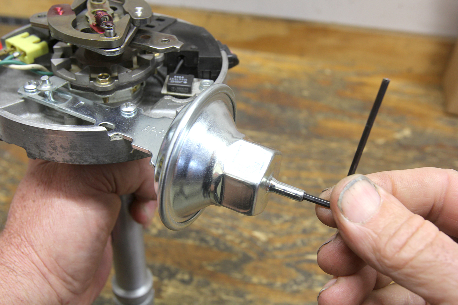
Early engine designers discovered they could use manifold vacuum connected to a simple diaphragm device that uses this vacuum to pull a rod that’s connected to the distributor baseplate to advance the ignition timing. In the 1960s and 1970s, there were hundreds of different vacuum advance canisters each designed for a specific engine combination.
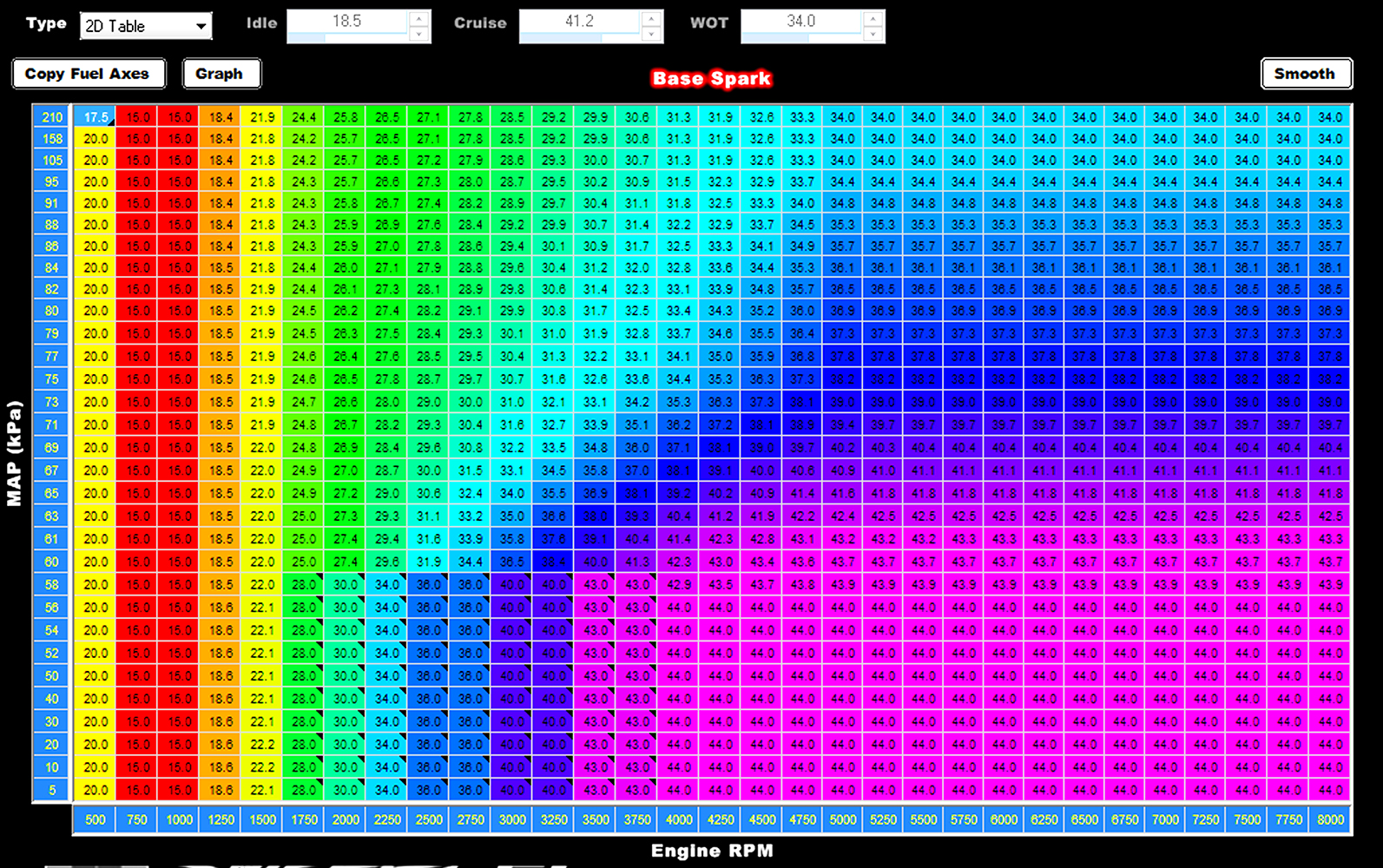
Getting into specifics, most street engines can enjoy measurably better throttle response, driveability, and fuel mileage by combining vacuum advance with the initial and mechanical settings. As an example, a typical small-block Chevy might need 36 degrees of total timing for best WOT torque and horsepower. But at light throttle, it will need additional timing in the range of 40 to 45 degrees BTDC (or more). Again, each engine will respond a little differently based on static compression ratio, cam timing, combustion efficiency, air/fuel ratio, and a host of other variables.
All vacuum advance numbers are added to the initial and mechanical advance at part throttle. As an example, let’s say that we now add vacuum advance to our 15 degrees of initial timing and that we’re cruising with an overdrive trans at 70 mph at 2,200 rpm. This puts our mechanical advance curve delivering 14 degrees of timing (total mechanical is not fully advanced at this low engine speed) that combines to produce 29 degrees BTDC of timing. Nearly all street engines will demand more timing than 29 degrees BTDC during part throttle cruising. Let’s add another 15 degrees of vacuum advance to enjoy the fruit of optimized ignition timing. This is equal to 44 degrees of total timing BTDC at part throttle.
Some enthusiasts may think that the engine will likely detonate and suffer damage, but this is not the case. Remember, the cylinder pressure is very low at part throttle, which is why it needs this additional timing. Of course, if the engine were running at WOT with that much timing, it would likely detonate. But remember, manifold vacuum drops to near 0 at WOT, so the vacuum advance is not present at high throttle openings. At WOT vacuum advance is not present, so we are back to the 15 degrees initial plus 20 degrees mechanical equal 35 degrees BTDC at WOT.
You can think of vacuum advance as load-based timing if you like because vacuum advance disappears as soon as the manifold vacuum drops below roughly 6 inches of mercury (Hg). Each engine will demand its own variations on this example. Some engines will want less vacuum advance and others will require more. Cylinder heads with less efficient combustion chambers tend to demand more timing than engines using more efficient chambers.
As a small addition to this overview, engines with the most efficient combustion space will always demand less ignition timing than combustion chambers with a less-efficient design. Older readers may remember when it was common for high-compression small-block Chevy engines from the late 1960s to demand 42-44 degrees of total timing for best power. Today’s highly efficient LS engines require much less total ignition timing numbers that are now less than 30 degrees.
There are limitations to this combination of initial, mechanical, and vacuum advance. As mentioned earlier, mechanical advance is a linear function based solely on engine speed. Vacuum advance is also linear with a given vacuum level producing a set amount of advance. An illustration of the limitations of these linear functions is a 468ci El Camino we tuned for a friend where the engine wanted a given initial and mechanical advance combination. But after setting the amount of vacuum advance the engine preferred at cruise, the engine would always lightly detonate at a certain part throttle opening that seemed to occur most often on freeway on-ramps.
We were forced to reduce the total vacuum advance and to slow the rate of vacuum advance in order to prevent light acceleration detonation. This was aggravating because backing off the vacuum advance measurably reduced fuel mileage during long cruises. The eventual solution was to convert to digital ignition since the engine already had a Sniper throttle body fuel injection.
With the ability to set very specific ignition advance numbers, we were able to advance the timing at cruise but still pull a couple of degrees of timing out in the load area where the engine otherwise rattled at part throttle acceleration. This is the advantage of digital control over the ignition that cannot be duplicated with linear advance curves using mechanical devices. It’s a small point, but the change to a digital ignition curve improved fuel mileage in that big-block by nearly 1 mpg.
There is much more to tuning the combination of initial, mechanical, and vacuum advance curves than we can cover here but armed with these basics you now have a strong foundation to work through the details for your specific engine combination. It’s a rewarding process to watch the engine respond to the changes you command. This is the best part of being a hands-on car guy. It’s like instant gratification when the engine immediately runs better after you’ve made a simple change.
| Parts List | ||
| Description | PN | Source |
| Summit HEI advance curve kit, weights, springs | SUM-G5212 | Summit |
| Summit adj. vacuum advance can, HEI | SUM-850314 | Summit |
| Mr. Gasket advance curve kit, GM points dist. | MRG-928G | Summit |
| Accel adj. vacuum advance can, GM points dist. | ACC-31034 | Summit |
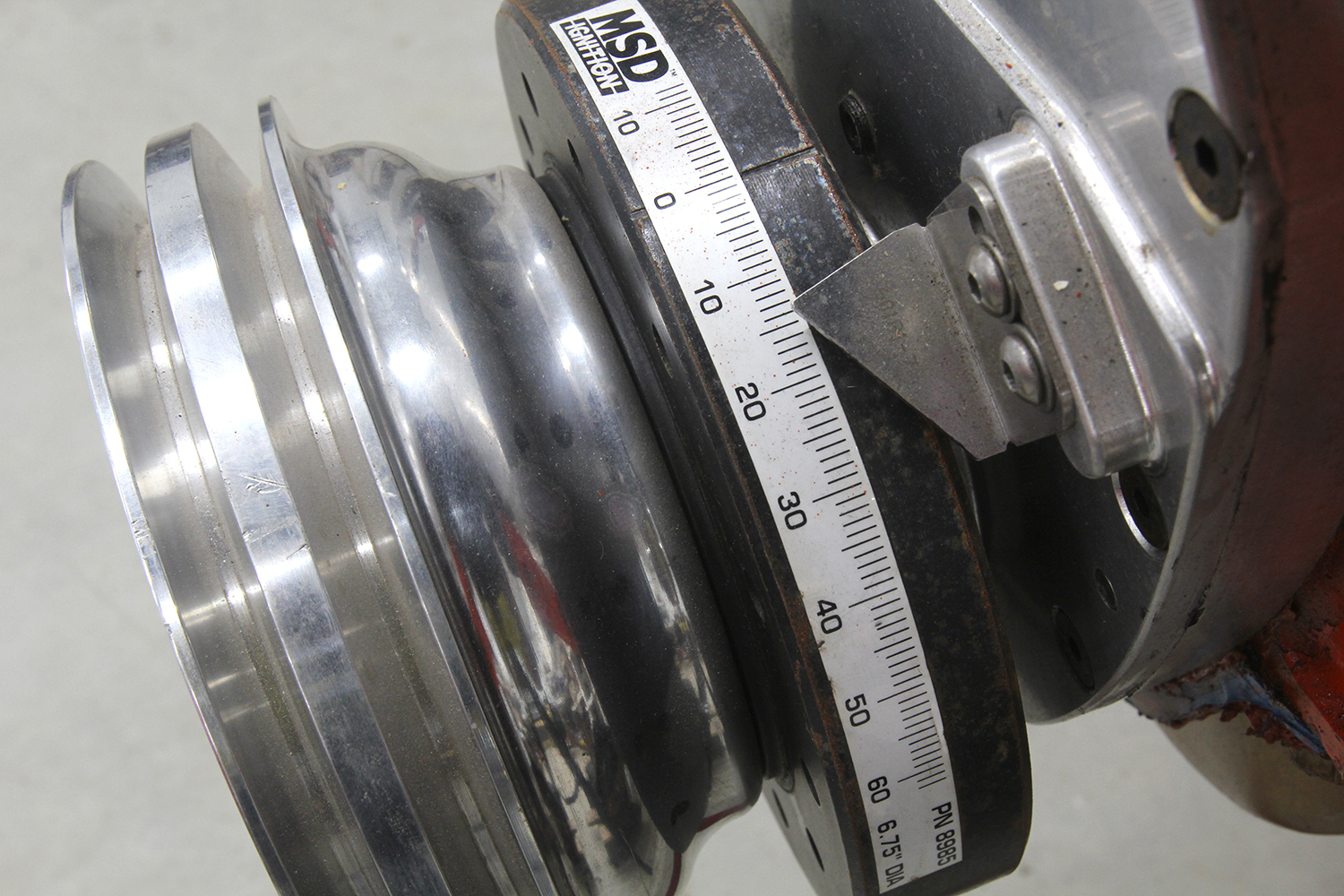
| MSD timing tape | MSD-8985 | Summit |
Check out this story in our digital edition here.