
Part 2: Avoid These Brake System Blunders!
By Ron Ceridono – Photography by Ron Ceridono and Courtesy of Wilwood, Classic Performance Products & Speedway Motors
There are some shortcomings in a hot rod you can learn to live with. An occasional rattle, a window crank that comes off in your hand, or a gas gauge that never seems to be quite right. One thing you may not live with is a malfunctioning brake system. If you are building or buying a car, here are some things to consider:

Picking the Proper Brake Line Tubing
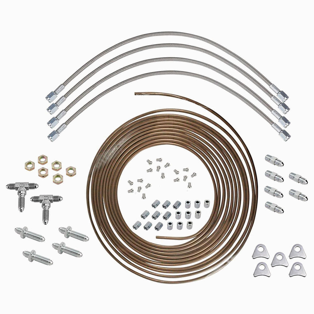
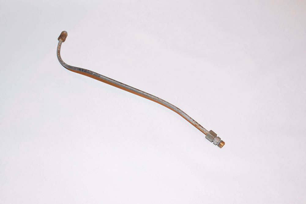
A brake system may produce well over 1,000 psi in operation, which requires brake lines, hoses, and fittings that can withstand pressure reliably—that means no copper or aluminum tubing. There are only three choices when it comes to brake lines—steel (usually with a tin coating to prevent rust), stainless steel (that is often polished), or nickel/copper (NiCopp) tubing that meets SAE Standard J1047 and ISO 4038, meeting all international and U.S. requirements for brake tubing. NiCopp is unique as it has the strength and structural integrity of steel lines but with the added benefit of being much more corrosion-resistant, and it bends easier.

There are two common misconceptions about brake lines. The first is that there is a relationship between brake line size and hydraulic pressure—not true. Pressure in the brake system is created by the master cylinder and the brake lines deliver it. Brake lines are most often 3/16 or 1/4 inch in diameter and the only difference is the amount of fluid delivered. The bigger tubing will carry more volume, so 1/4-inch line may be preferable in some instances, disc brake calipers with large piston displacements, as an example.
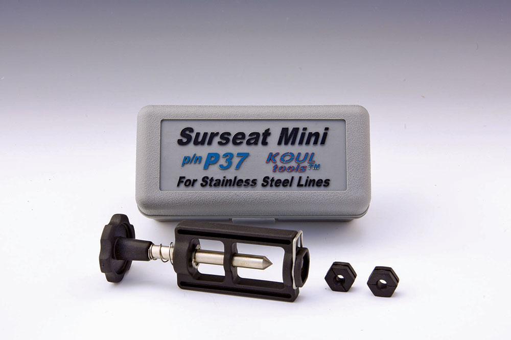
The second misconception is that stainless steel brake lines cannot be double flared. It is true that some stainless steel tubing will crack when forming double flares, however it can be done if the appropriately annealed tubing is used.
Read More: Everything You Need To Know About Brake Fluid For Your Hot Rod
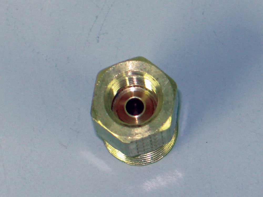
Making Connections
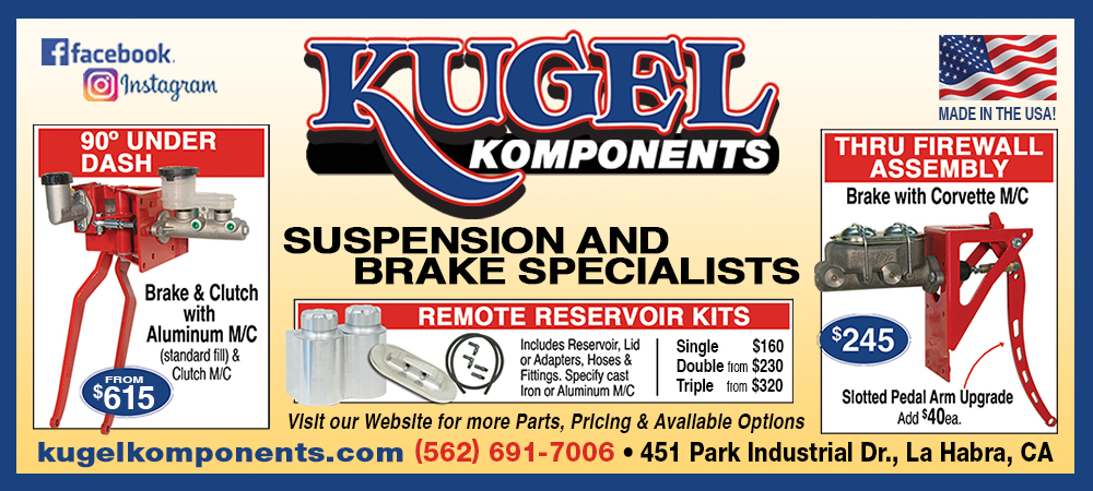
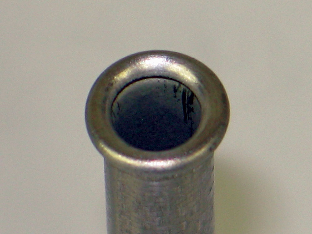
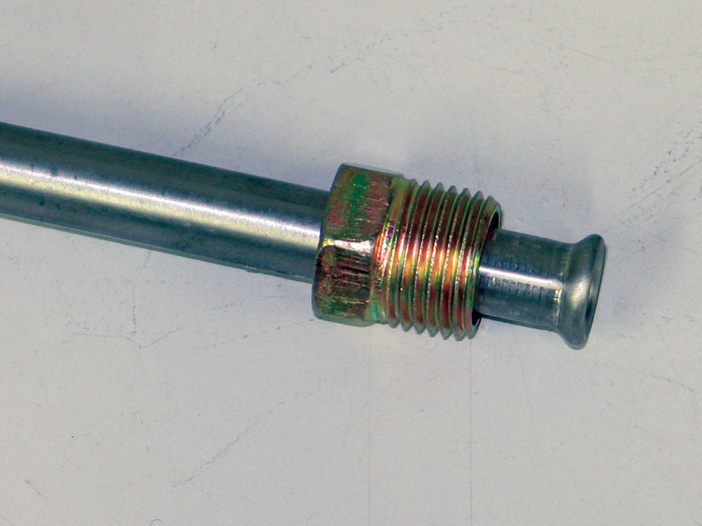
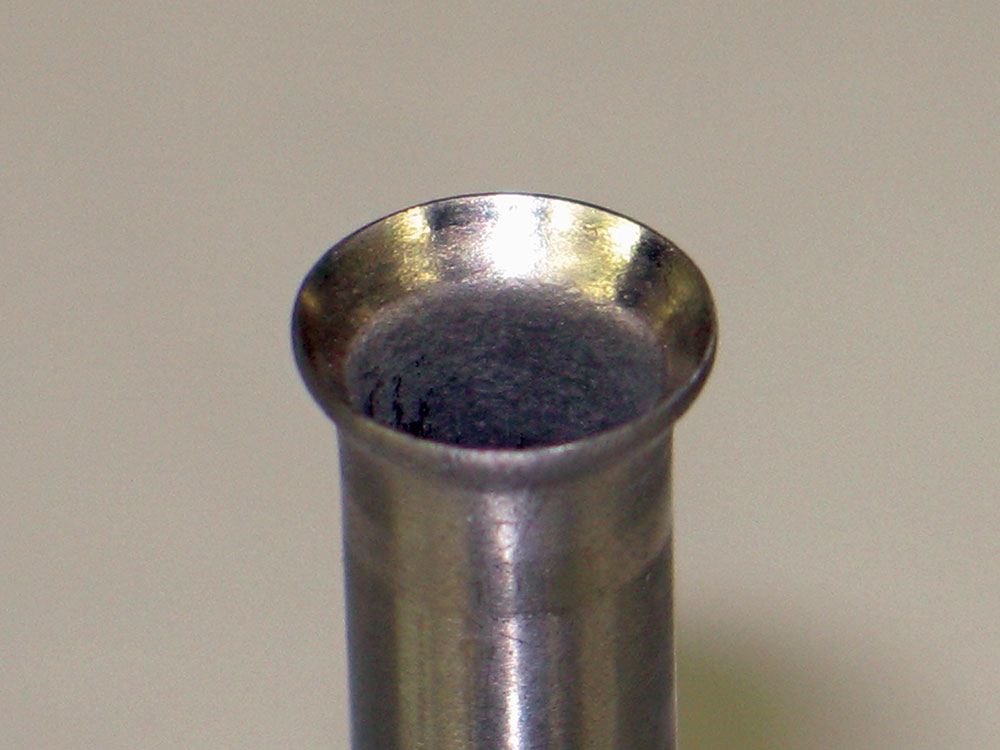
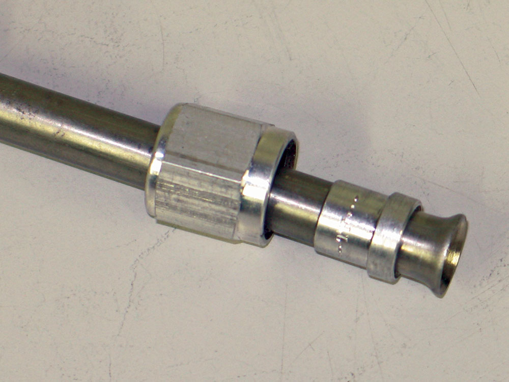
The most common type of hydraulic connections found on automobiles is the SAE 45-degree double-inverted flare. That means the tubing is flared and then folded back on itself for increased strength and resistance to cracking. The tube’s flare is clamped between the nut and the seat in the fitting when screwed together so when the assembly is tightened, a leak proof metal-to-metal joint is created and no sealer or Teflon tape is necessary.
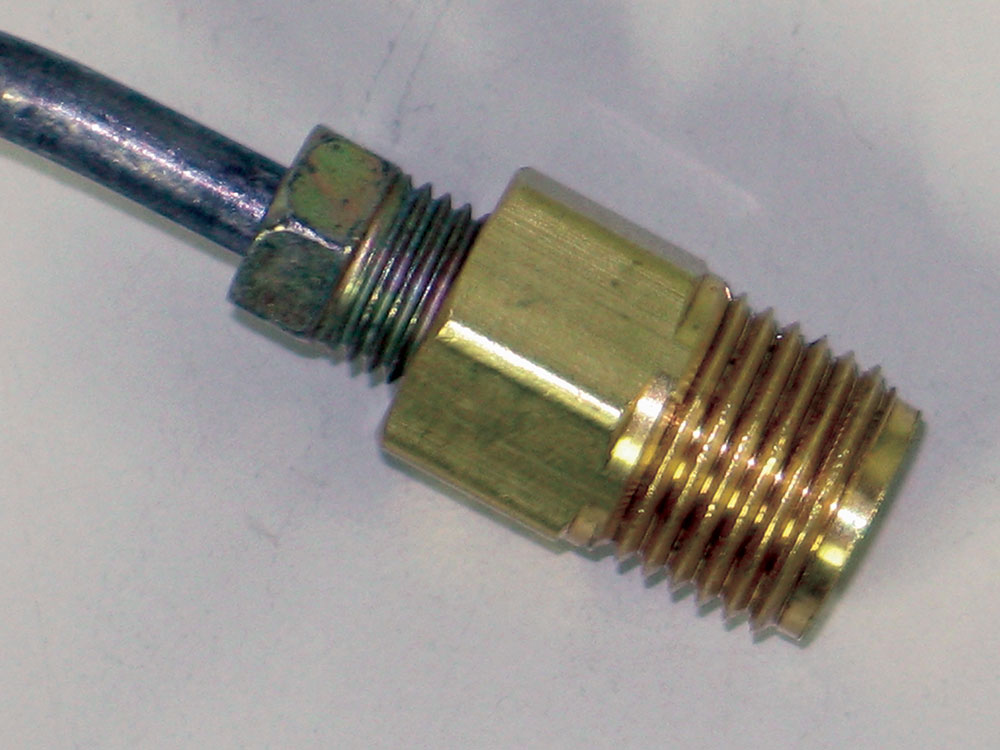
While they aren’t used on production automobiles, AN fittings are often found on hot rods and race cars. (The reference “AN” stands for Army/Navy and it’s a system that was developed by the government to ensure interchangeability and compatibility of parts made by various manufacturers.) AN fittings use tubing with 37-degree single flares with reinforcement sleeves (37-degree flares will also be found on JIC hydraulic fittings).
The AN system uses a number to identify the various sizes of metal tubing and the corresponding fittings, and the same numbers are also assigned to the hose and their ends. Called dash numbers, they equate to 1/16 inch. As examples, -3 AN line is 3/16 inch, -8 is ½ inch.
Fittings

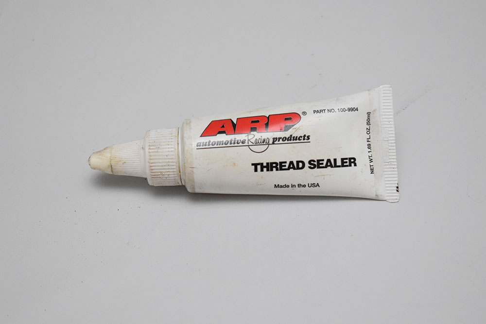
The common fittings used on production cars have National Pipe Threads (NPT). Pipe threads differ from fasteners and other fittings as the threads are tapered—they screw together until they tighten due to the taper. To create a leak-free seal, NPT threads often use some sort of sealer, such as Teflon tape or a leak-preventative paste.
There are a variety of adapters available to connect different types of fittings—they make it possible to mix and match inverted flare, pipe, and AN fitting as well as connect standard and metric sizes.
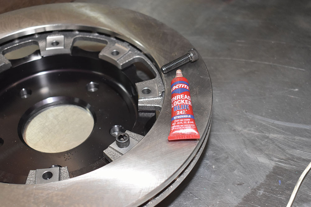
Sealants
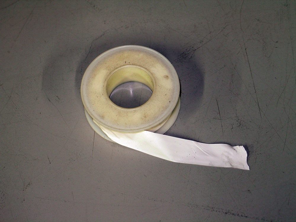
Compared to every other automotive product known to man, Teflon tape is likely the most often misused. Although Teflon tape can cure leaks, prevent thread galling, and protect fittings from corroding it’s often used on the wrong fittings. Teflon tape should never be used on inverted flare fittings as they are designed to seal without it. An alternative to tape is Teflon paste for fluid-tight seals.
Read More: How To Install Modular Brake Kit and Spindles
Brake Valves
Hot rods often have peculiar brake system needs, resulting from the configuration of the components.
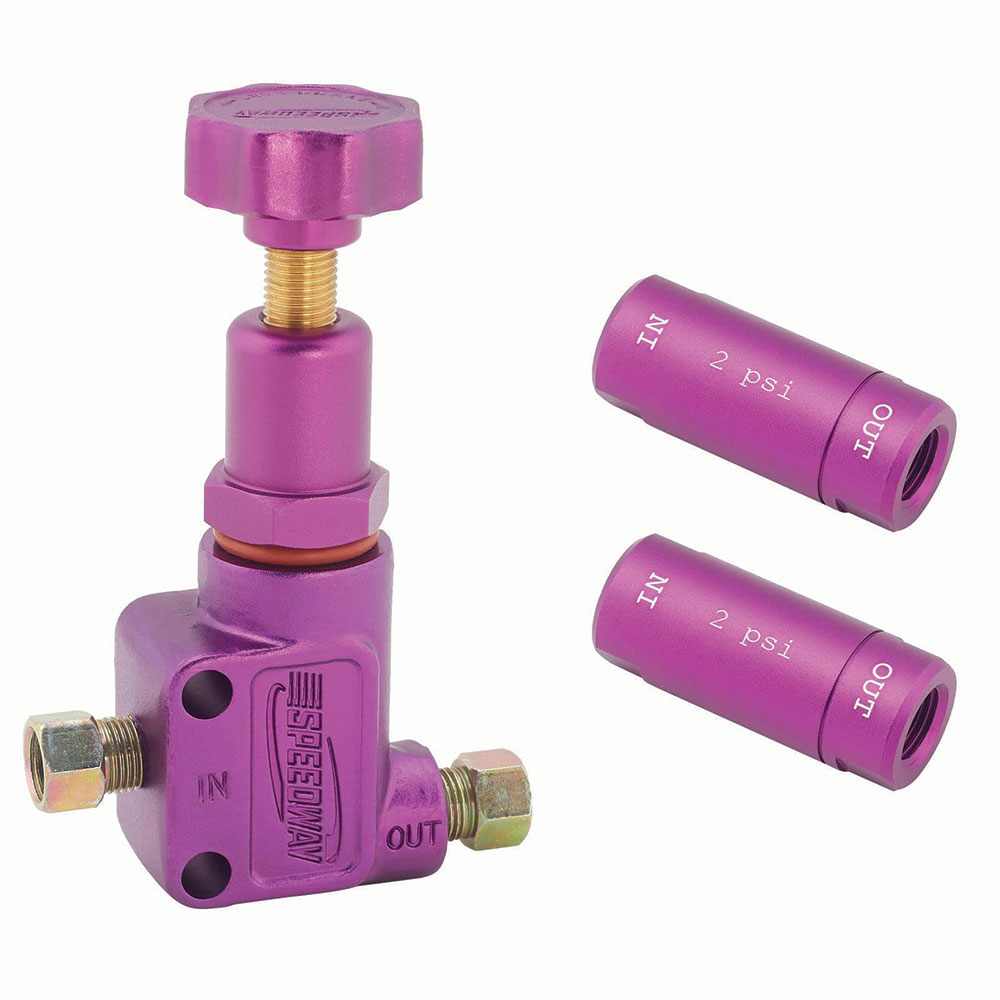
A typical combination would be a master cylinder mounted below the floor that is lower than the disc brake calipers. As a result, fluid will tend to drain out of the brake calipers and back into the master cylinder. The result is the brake pedal has to be pumped to bring the pads back in contact with the rotors, not a great situation in a panic stop. The cure would be a 2-pound residual pressure valve that would maintain enough pressure to prevent the brake calipers from draining and keep the pads close to the rotors, but not enough pressure to make the brakes drag. In the case of a firewall-mounted master cylinder a residual pressure valve is not normally required for disc brakes.
When drum brakes are used a higher-pressure residual valve is required. Due to the strength of the return springs, a 10-pound residual valve is required to maintain sufficient line pressure to keep the wheel cylinder cups expanded. This prevents air from being drawn into the system, creating a spongy brake pedal and allowing the brakes to react quicker with a firm pedal. It should be noted that most OEM drum and disc/drum master cylinders have integral residual valves in the outlet to the drum brakes.
Brake proportioning valves are very often a part of a hot rod’s brake system. They modulate the pressure in the hydraulic system to minimize rear wheel lockup found in hard braking and to compensate for differences in braking conditions in front disc/rear drum systems. Pressure adjustments usually range from 100-1,000 psi and provide a maximum decrease of 57 percent in line pressure, which allows fine-tuning of the front-to-rear braking balance by proportionally decreasing the rear (or in some cases the front) brake line pressure. Adjustments are made by a knob with an arrow indicating the direction required to decrease line pressure. With the knob rotated all the way out (counterclockwise) there will be the maximum pressure reduction (usually around 57 percent). Rotating the knob clockwise will increase line pressure, up to 100 percent.
Often found on OEM systems with disc brakes are metering valves, they don’t allow pressure to the front disc brakes until the pressure at the rear drums overcomes the brake shoe springs. At this point the valve opens to allow full pressure to the calipers. In some applications a combination valve is used that incorporates metering and proportioning functions into one valve. They often have warning light provisions to indicate if one half of a dual brake system has lost pressure.
Read More: Brake System Rehab: 1972 Ford F-100
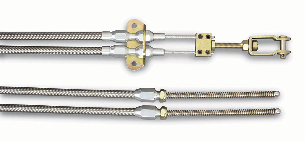
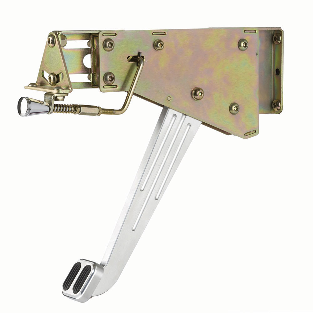
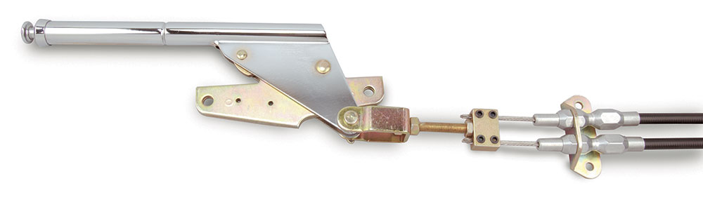
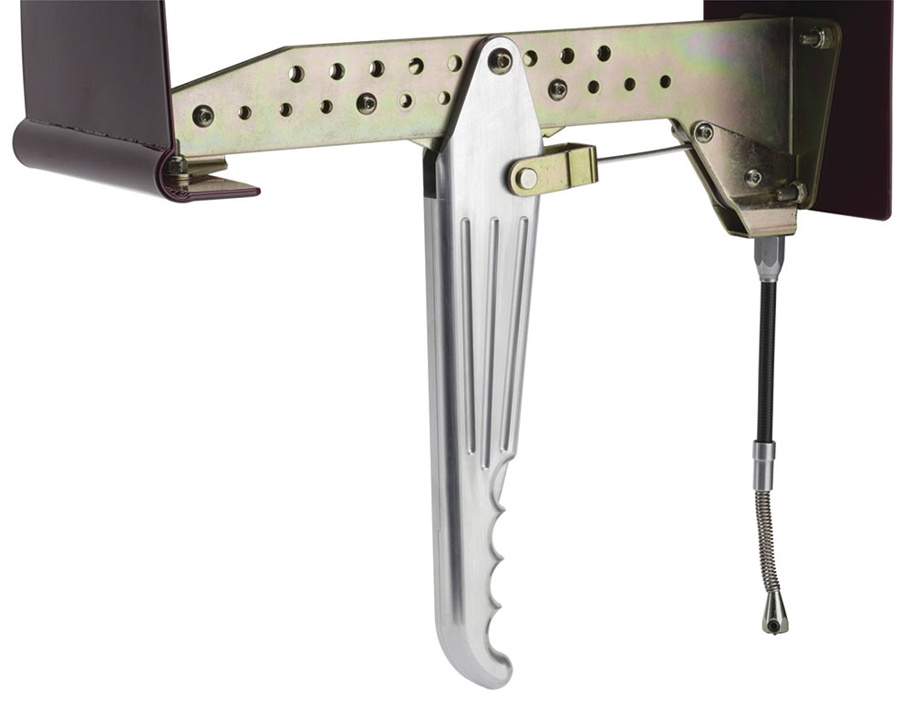
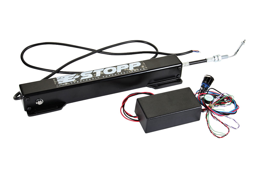
Parking Brakes
At one time parking brakes were referred to as an emergency brake, for good reason in the days before reliable hydraulic brake systems. Thankfully those days are past, but unfortunately a byproduct of better brakes is that functional parking brakes are not often considered. Speaking from experience, we’ve pulled on a parking brake handle only to find out nothing that was supposed to happen happened. All cars should have a functional parking brake—a good test is that the parking brake should hold the car with the engine running and an automatic transmission in gear, or it should kill the engine with a manual transmission when the clutch is released.
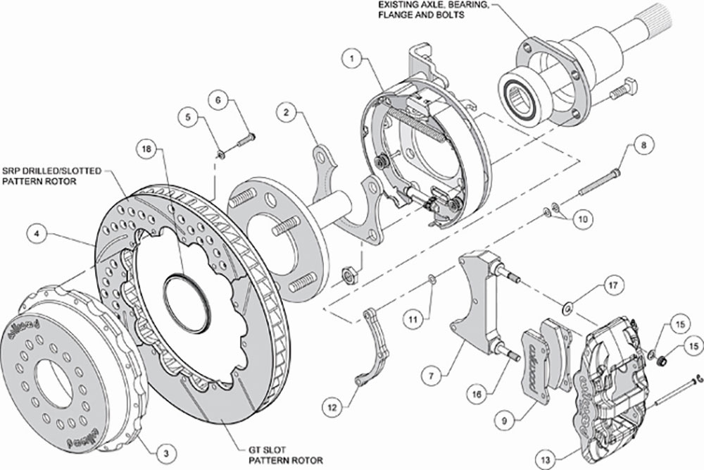
Breaking in Brake Pads
When installing new disc brake pads, it may take stroking the brake pedal a few times to move the pads closer to the rotor. According to Wilwood, once that is done new brake pads are best optimized by bedding in the same conditions and temperatures they are designed to operate in. A street pad can be optimized through typical street-type driving. A street pad does not need high temperatures to properly bed-in. Simply performing a series of stops that simulates street driving in a safe environment will give the pads a chance to bed-in.
One Last Precaution
This is simple enough—keep brake lines away from moving parts, sharp edges, and sources of heat. Make sure they are secure by using clamps every 18 to 24 inches so they can’t move or vibrate, which can cause damage, resulting in a leak. Make sure flex lines are long enough to accommodate full suspension and compression travel and steering movement.
Follow a few simple concepts, use the proper components, and perform regular inspections and maintenance, and you’ll avoid making any brake blunders. MR

Source
Classic Performance Products
(800) 522-5004
classicperform.com
Lokar Performance Products
(877) 469-7440
lokar.com
Speedway Motors
(800) 979-0122
speedwaymotors.com
Wilwood Engineering
(805) 388-1188
wilwood.com