Aluminized exhaust tubing. While it has its place (motorhomes, rat rods, demolition derby cars, and so on), it’s not under any self-respecting muscle car, street machine, or restomod build. Back when the only option was to drag your car to the local muffler shop, it made sense to have them whip up a dual-exhaust setup out of aluminized tubing. That was simply the way things were. Today, however, with the availability of affordable welding machines and exhaust kits designed for the DIY guy, it’s a lot easier to justify fabricating a custom exhaust system from a more exotic material, like stainless steel.
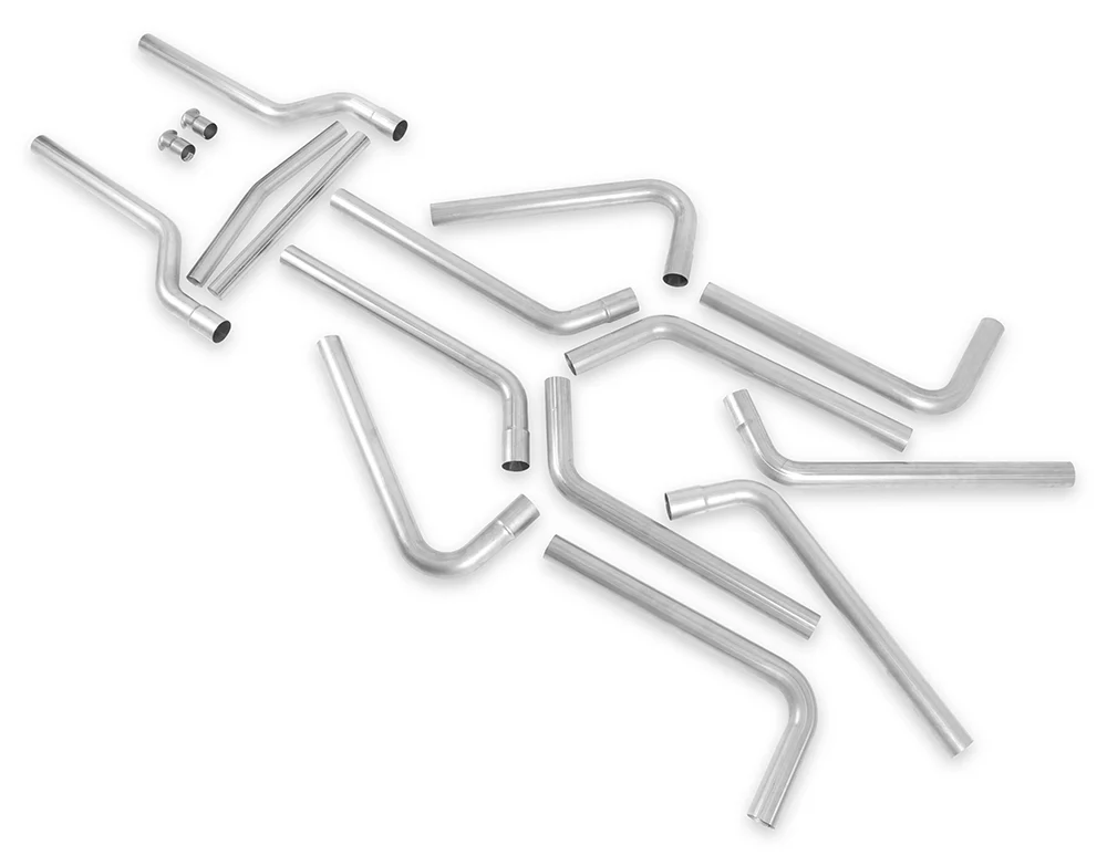
Here at the Clampdown Competition headquarters, we’ve found that Flowmaster’s Stainless Steel U-Fit Exhaust Kits provide a great foundation upon which to build a custom exhaust system. Fabricated from 16-gauge, mandrel-bent 409 stainless tubing, Flowmaster’s U-Fit kit features a variety of different bends, allowing the builder to route the exhaust through even the tightest of situations with ease. Their kit also includes adapters and intermediate tubing for H-pipe fabrication. For our LS3 powerplant we’re going to go with Flowmaster’s 2 1/2-inch-diameter stainless U-Fit kit (PN 815936).
There are drawbacks, however, to this line of thinking. Many guys don’t have the equipment to fabricate such a system or the ability to do so. But if one can TIG weld, read a tape measure, use a level, and retain a level of basic common sense, fabricating one’s own stainless exhaust system is not such an abstract idea.
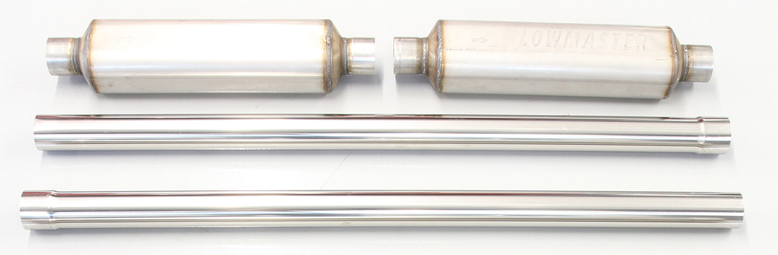
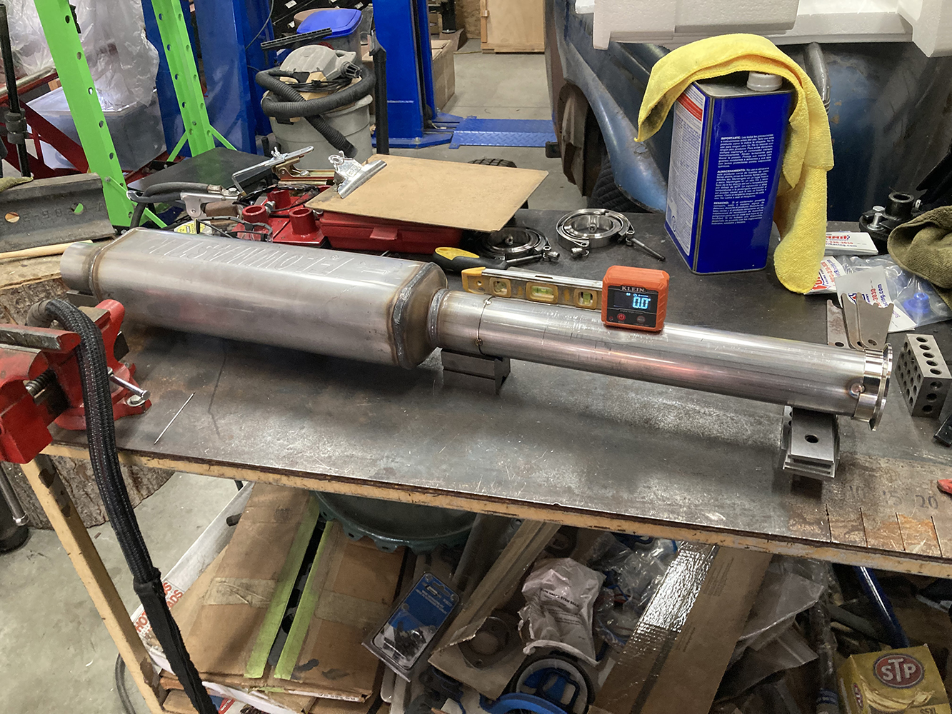
To help mellow the roar of the LS3, we’ll be using a pair of stainless Flowmaster Super HP-2 mufflers (PN 12518304). These offer a moderate tone with great performance benefits found on similar laminar-flow mufflers in a compact size, with a diameter of 4×5 inches and a length of 18 inches. Given the extra-long length of Bruce Valley’s Handyman Wagon, we also went ahead and ordered an extra pair of 45-inch stainless steel straight exhaust tubing from Summit Racing (PN SUM-640272), just in case.
Equipment and abilities aside, there are options for a myriad of muscle cars for complete, bolt-in systems in addition to U-Fab kits, catered more to the advanced TIG-able DIY folks. That 1969 Camaro with an LS swap? There’s a very high likelihood that someone makes a bolt-in stainless exhaust kit that can be installed using simple hand tools. But for those of us with an inflated sense of capability and a well-equipped shop, a fully custom stainless exhaust system can be fabricated at home, without expensive benders or exotic tools.
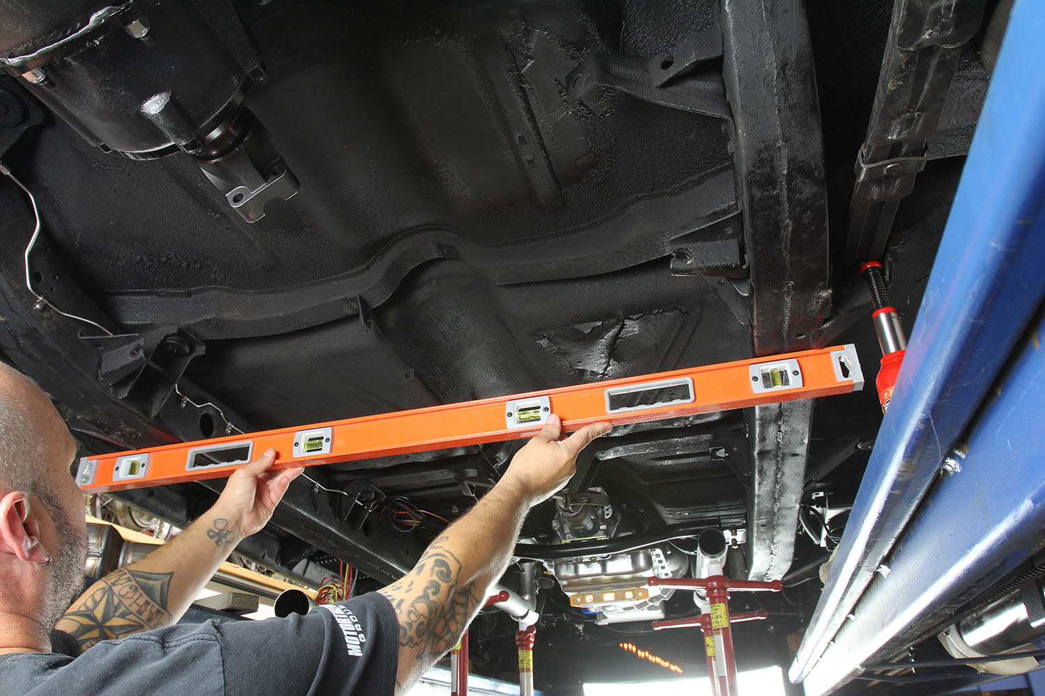
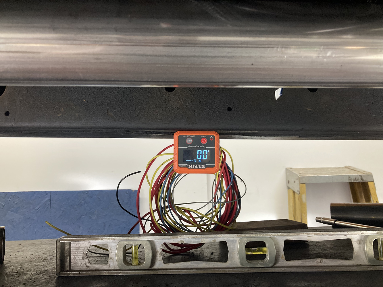
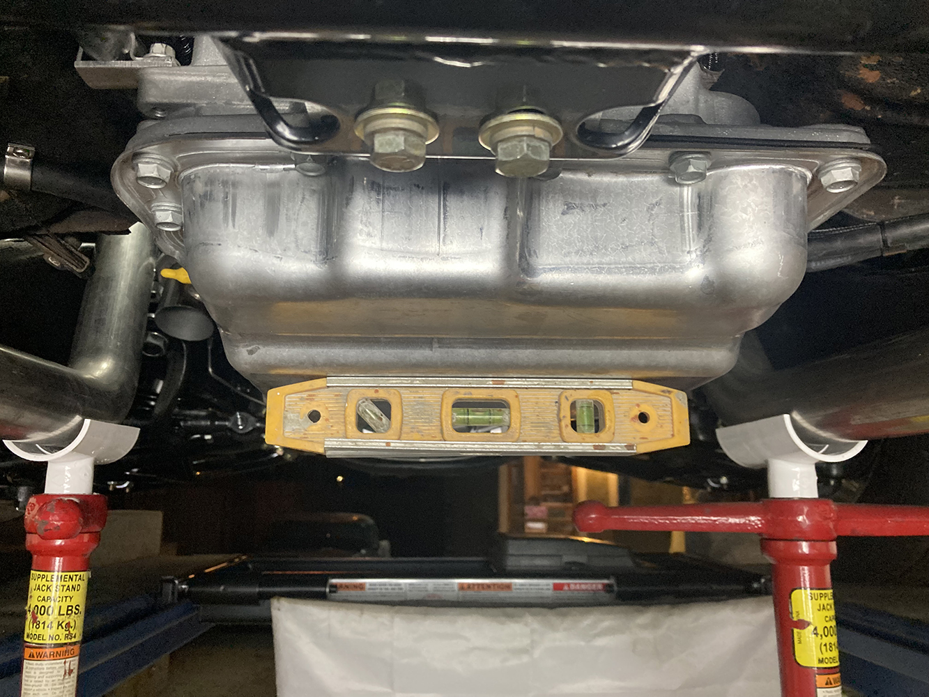
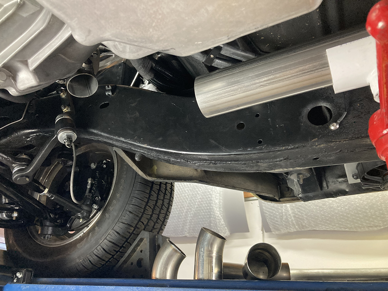
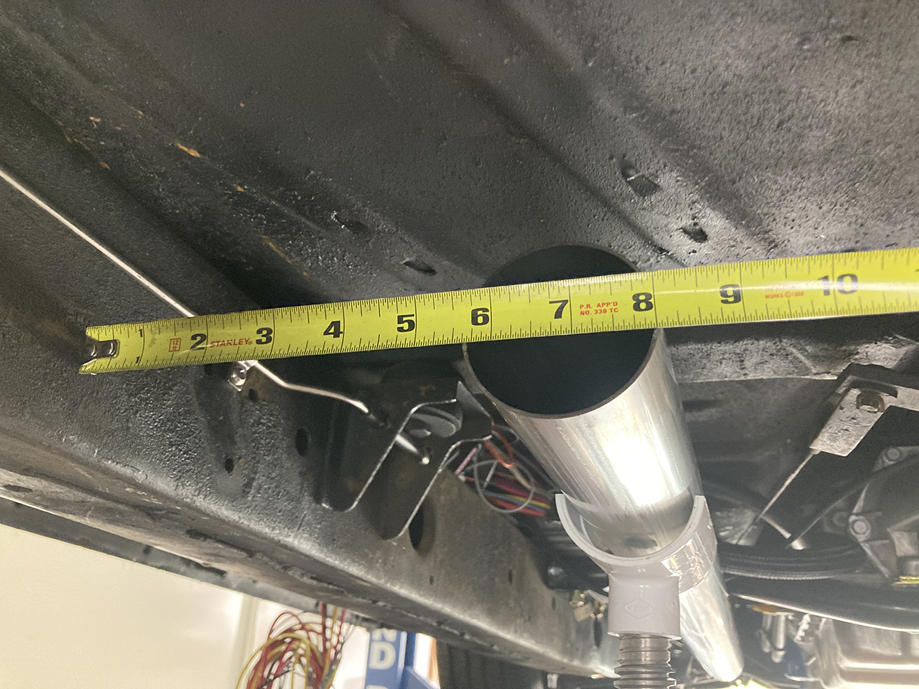
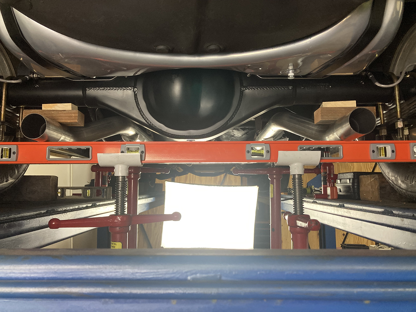
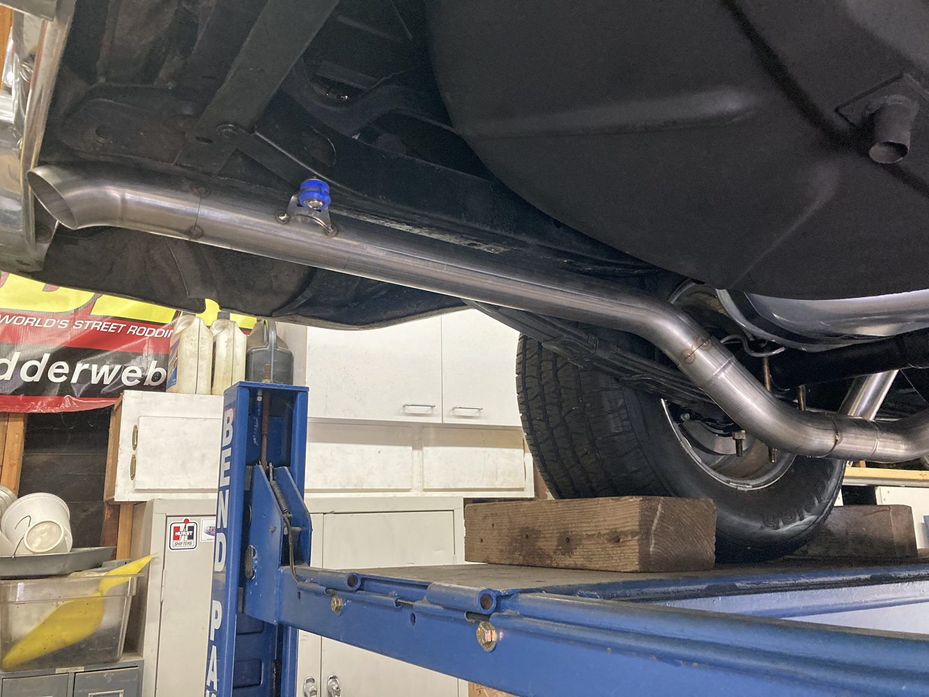
With the wagon on our four-post lift, we begin by getting the chassis nice and level both laterally and longitudinally. This ensures that as we fabricate our exhaust, the measurements taken are relative to each other and in the same plane.
If you’ve been following the progress of our buddy Bruce Valley’s 1957 Chevy Handyman Wagon these past couple months, you’ll likely know that things have been progressing fairly well at the Clampdown Competition garage, with the LS swap complete and the suspension components fully sorted. Work has begun on the plumbing side of things, with the brake lines completed and the fuel system following closely behind. As one job gets crossed off the list, another is started, slowly shortening what seemed like an epic saga into a manageable to-do list. Next up? One-off, full-length stainless exhaust using a U-Fit kit and Super HP-2 mufflers from Flowmaster. We’ve installed a few of these combinations and have been very pleased with the variety of bends provided, the quality of material, and the final sound of the finished exhaust, resulting in a slightly aggressive tone without the bark of a cheap “Turbo” muffler and almost zero drone.
Valley wanted a hot rod vibe to his wagon, and we think this combination will provide just that, while looking just as good as the rest of the car.
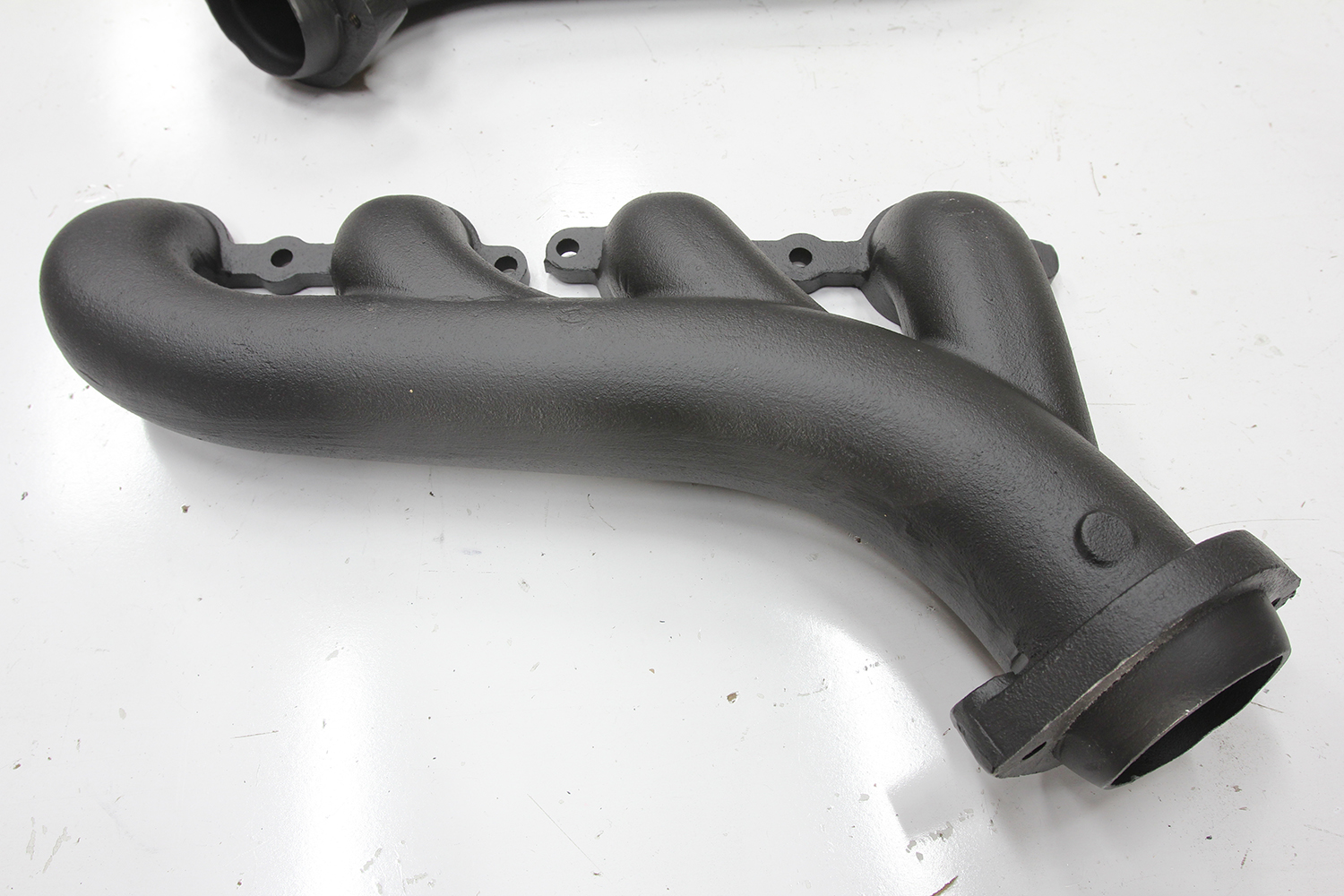
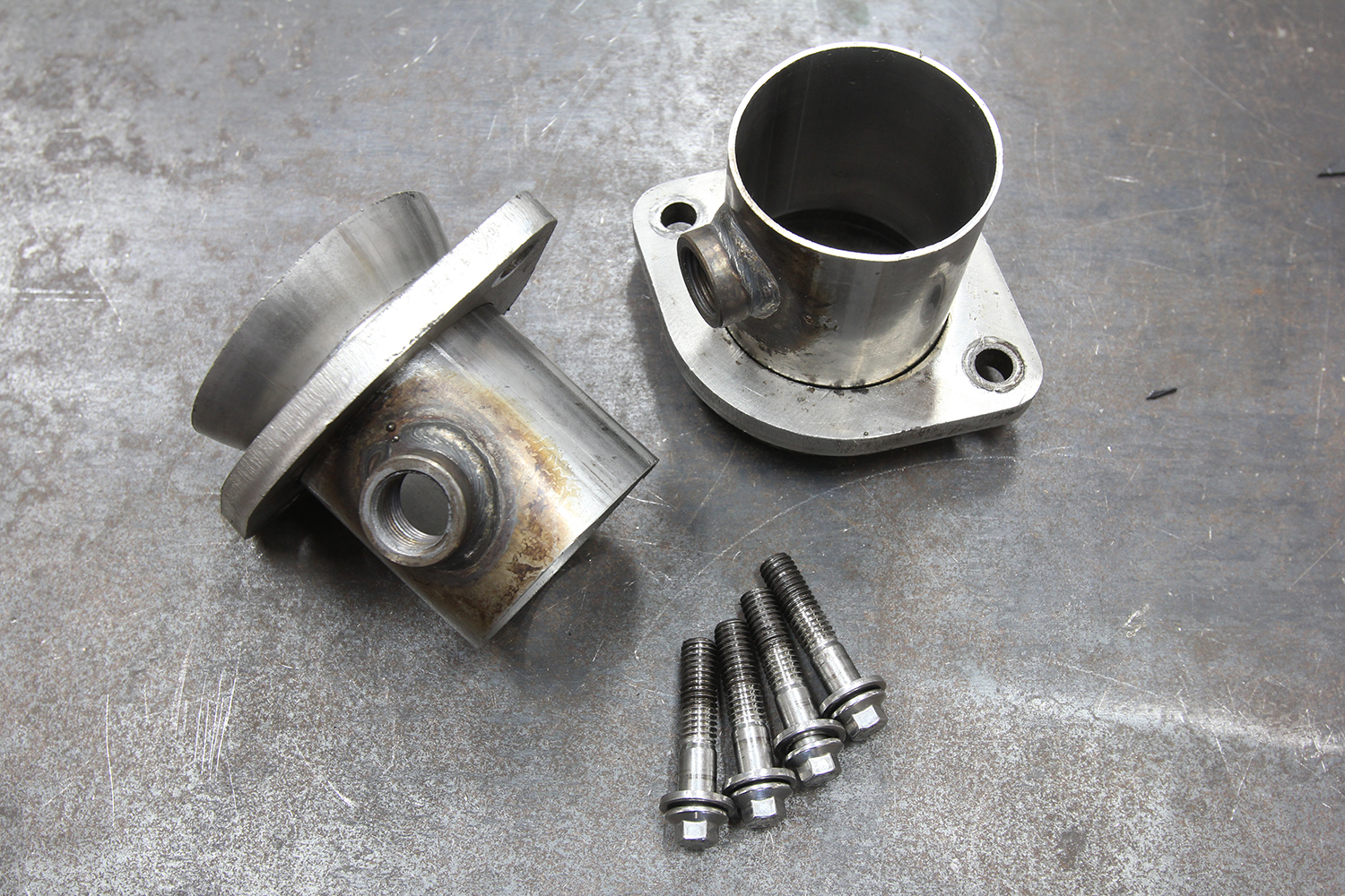
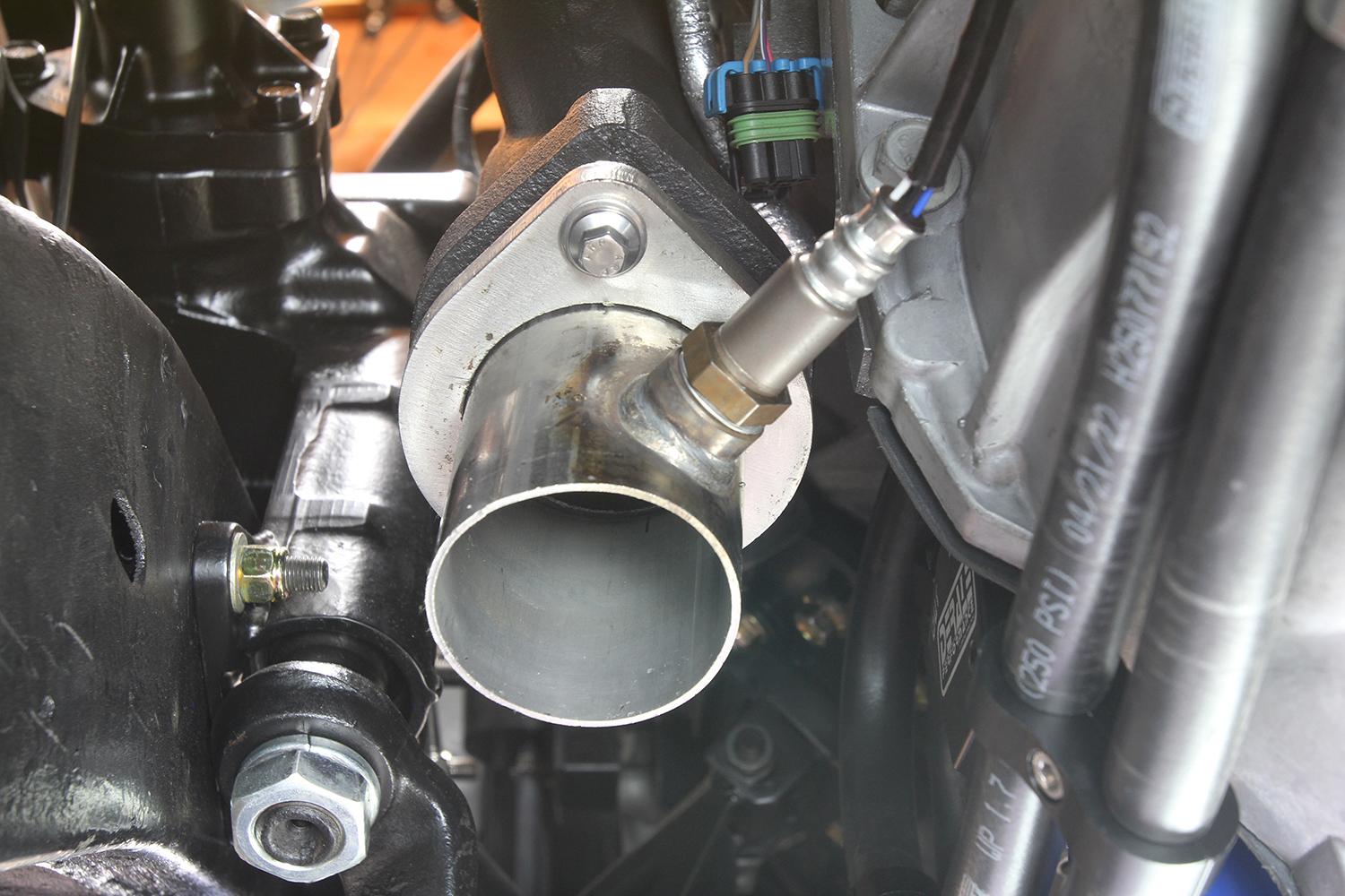
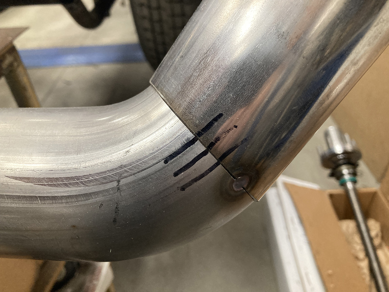
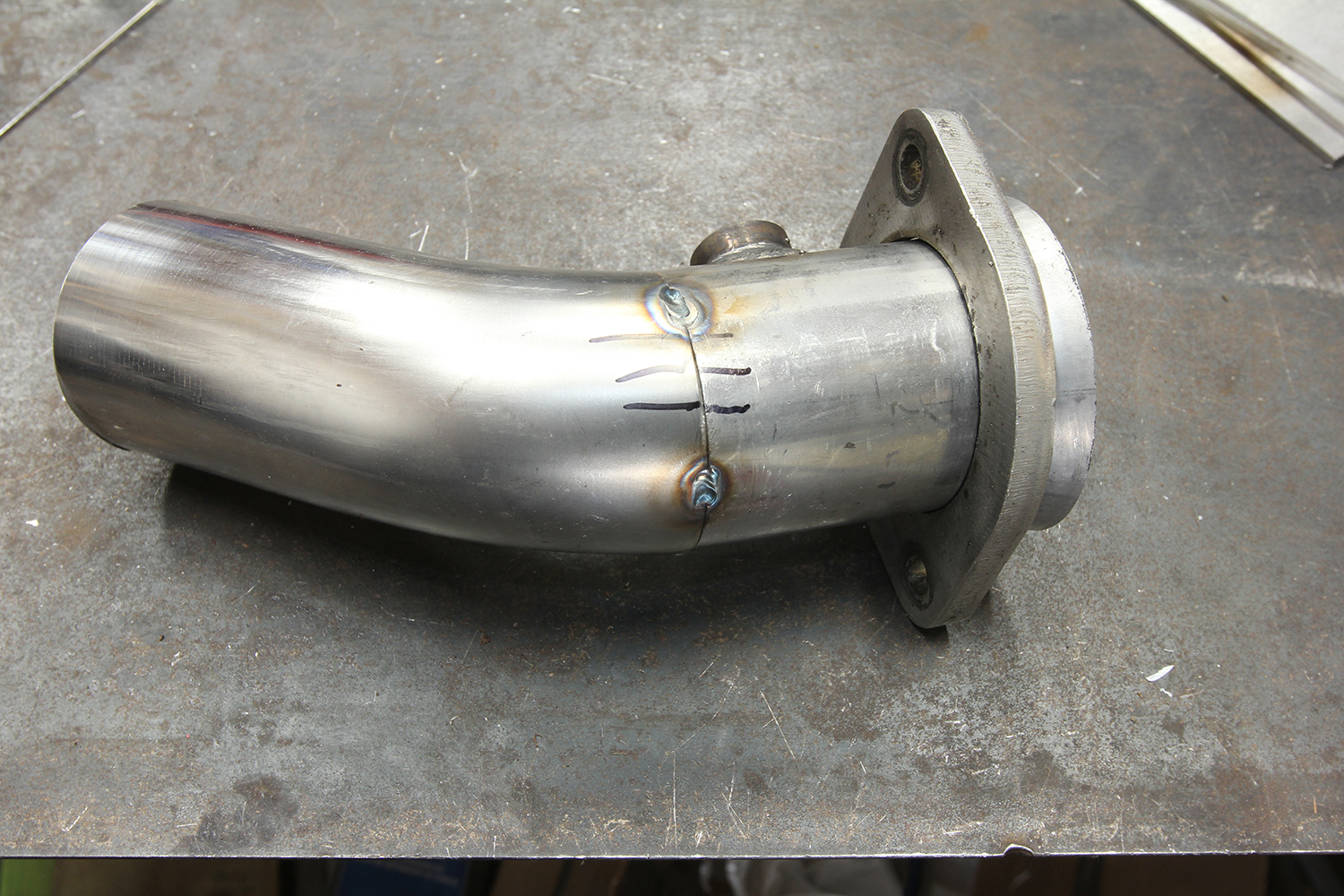
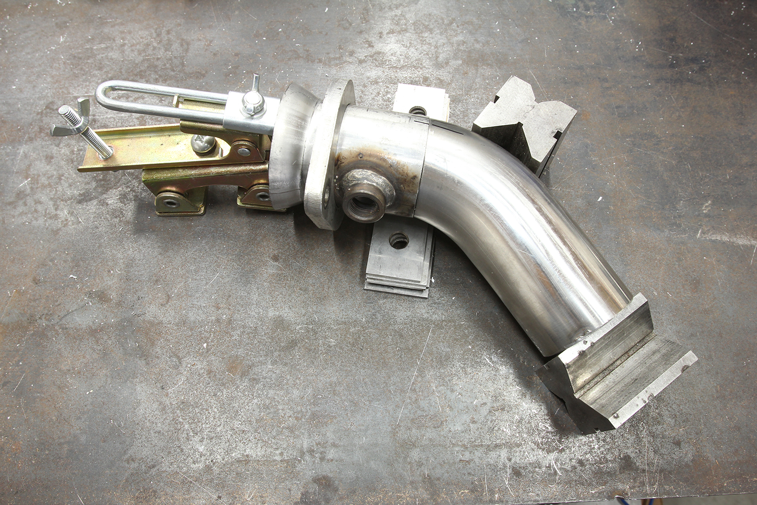
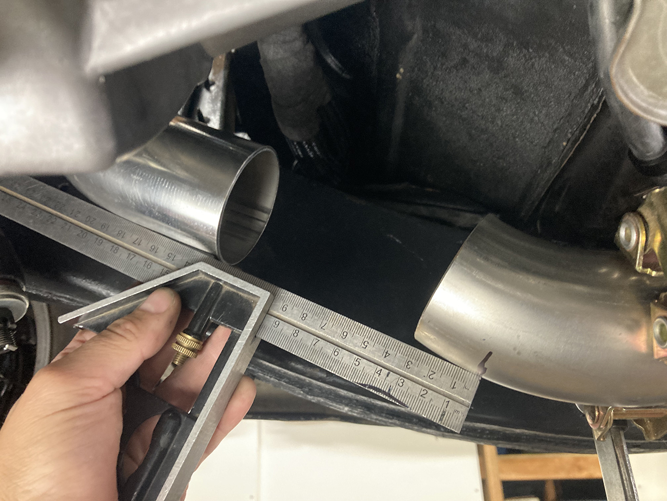
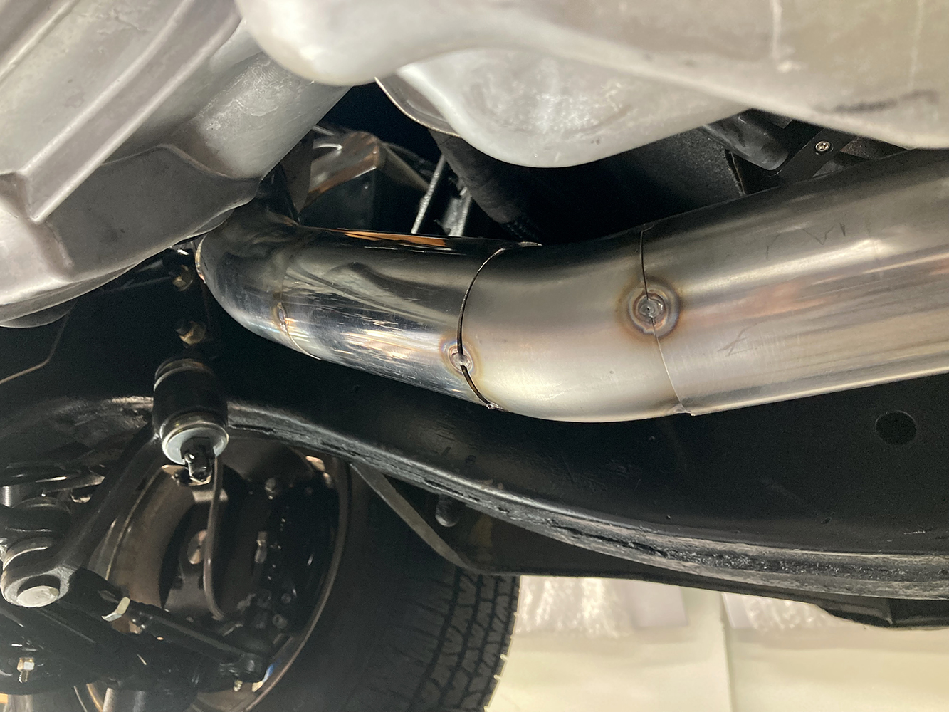
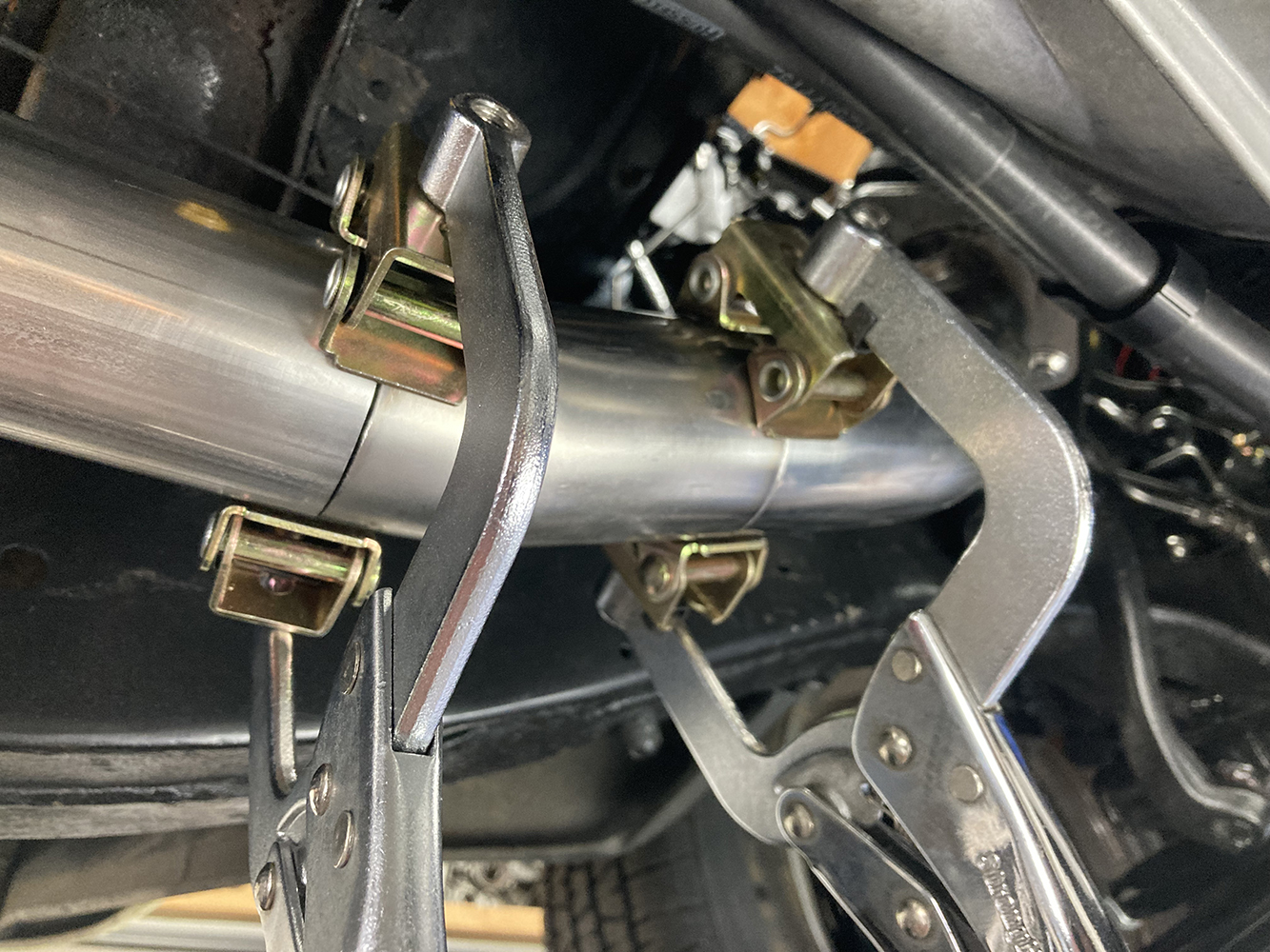
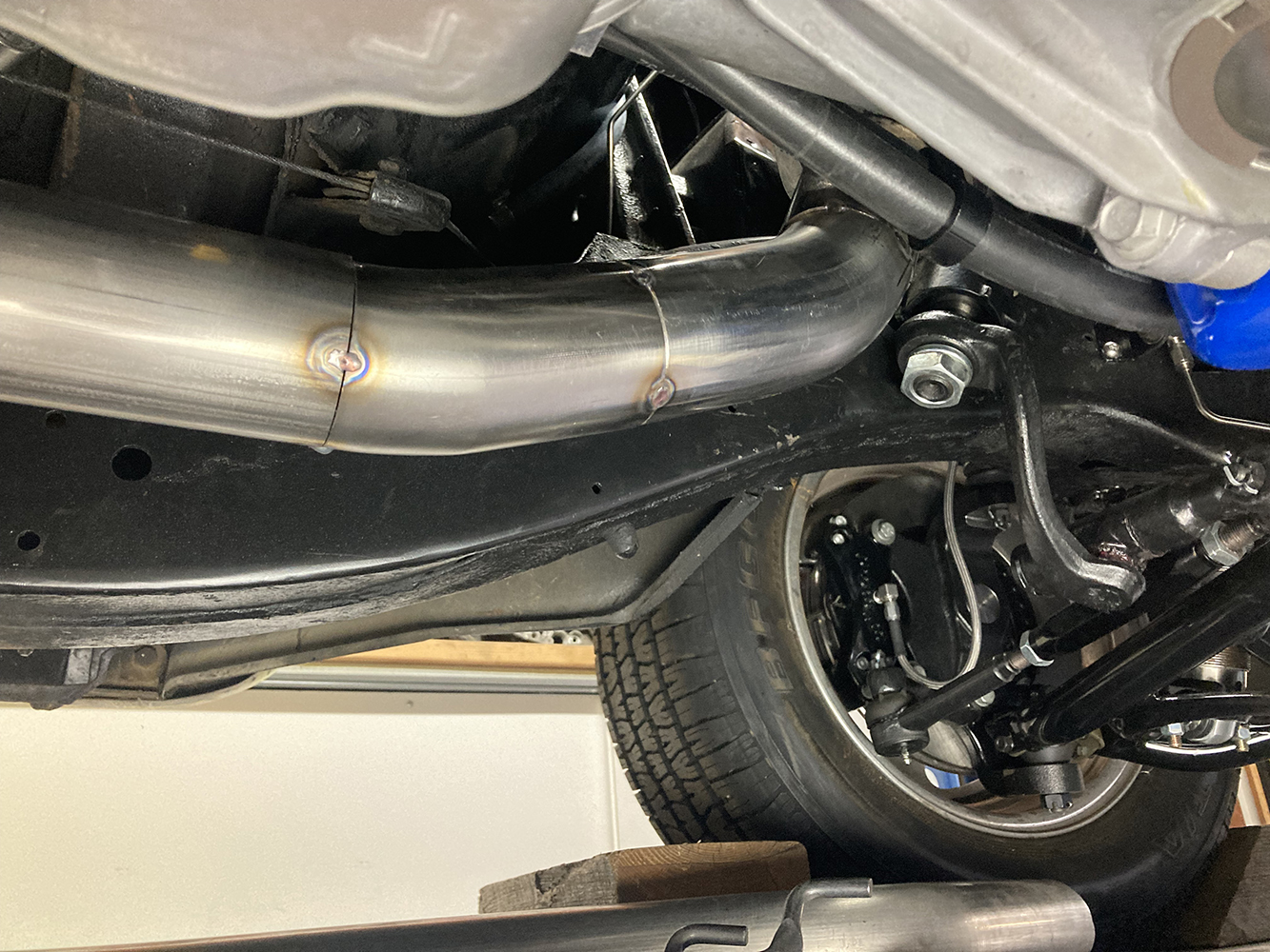
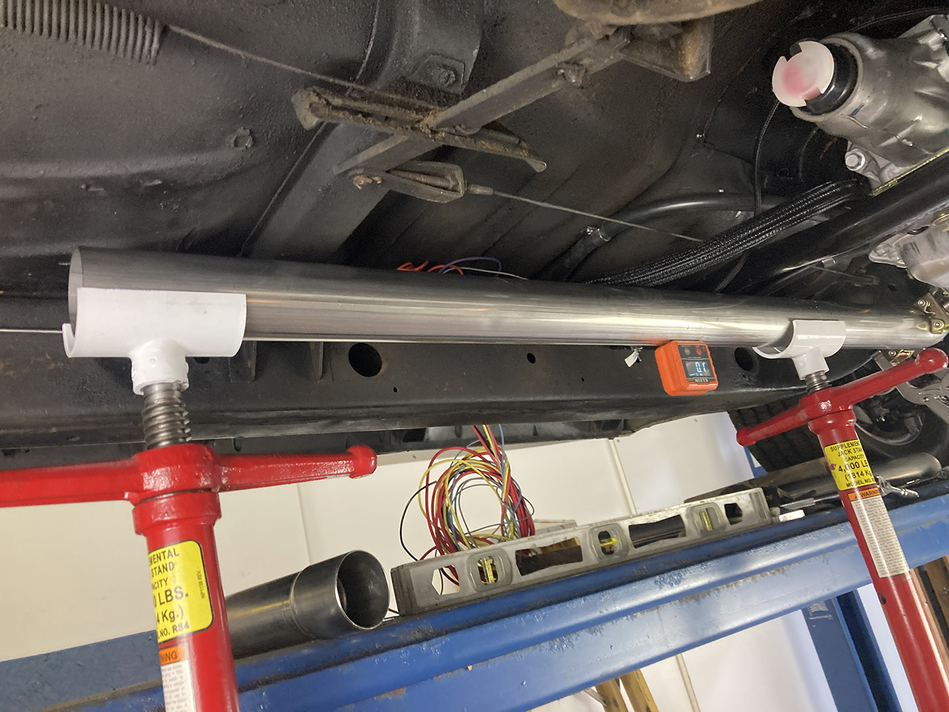
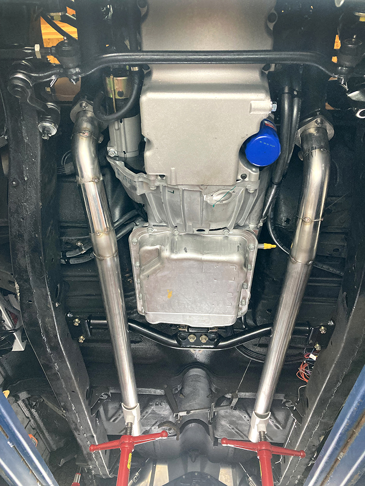
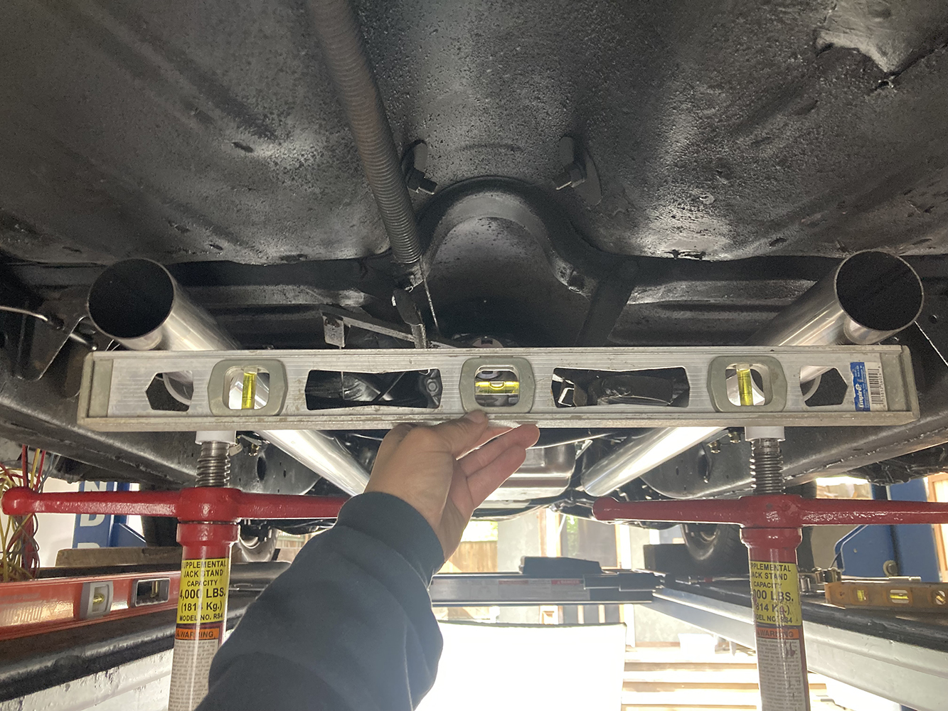
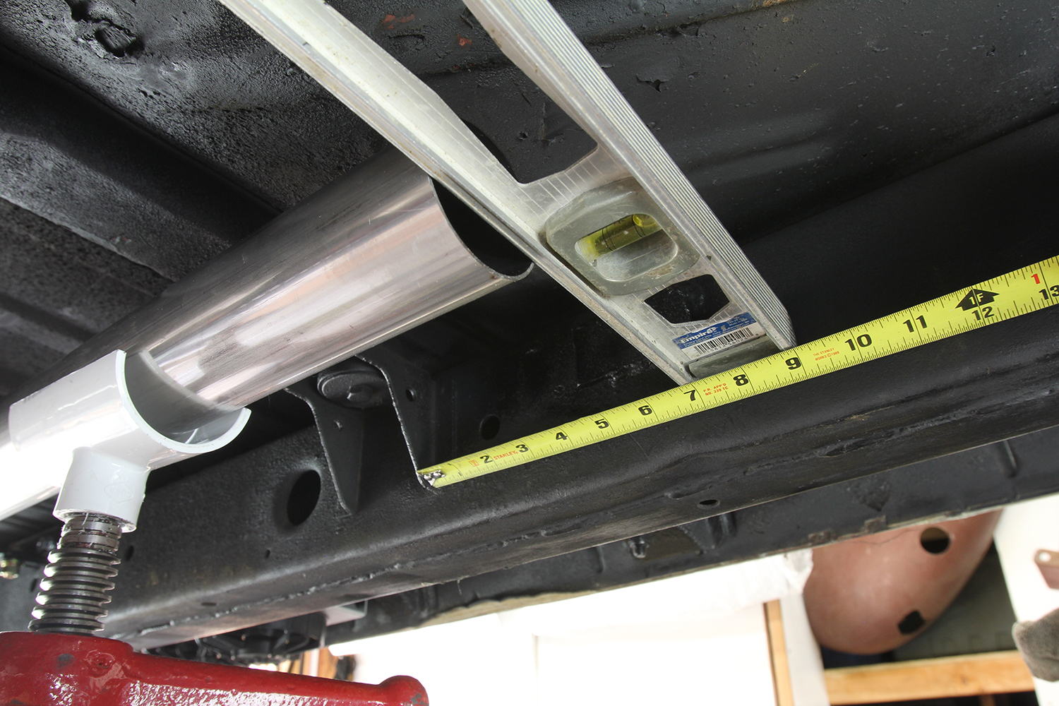
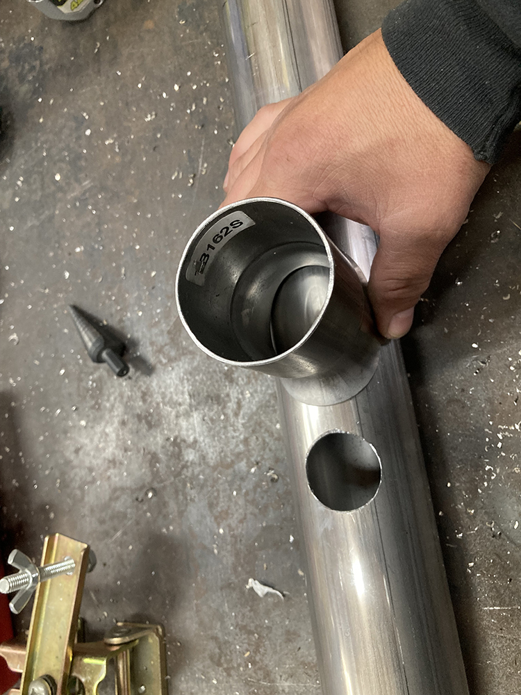
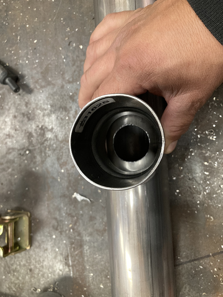
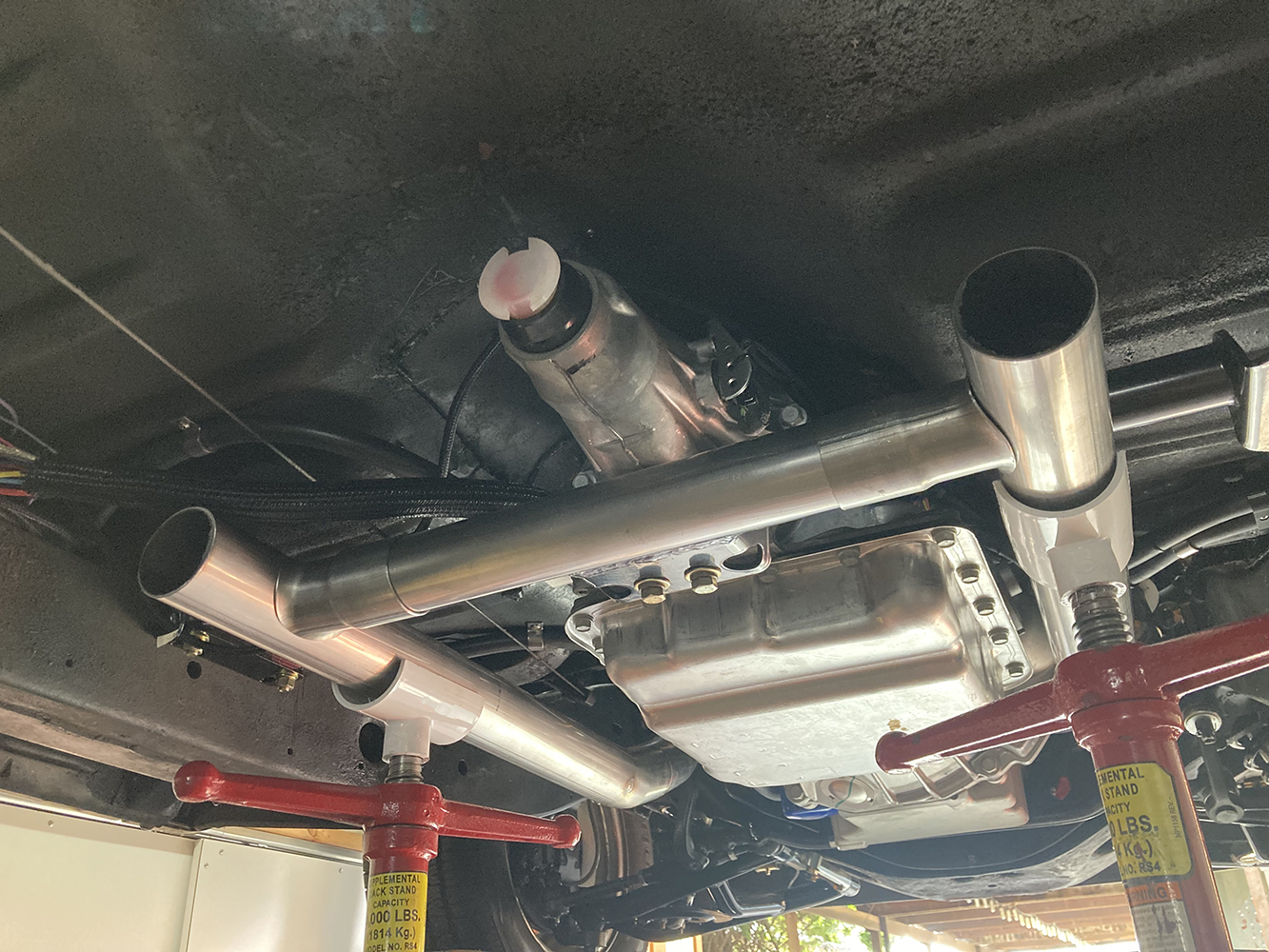
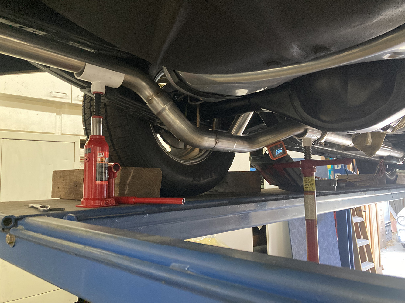
The stock LS3 exhaust manifolds can be a bit of a bear to fit in an older car, making the swap to Summit Racing’s Cast Exhaust Manifolds (PN SUM-G9084B) a given. These high-silicone ductile-iron castings feature a Black Ceramic Coating, providing an attractive finish with performance numbers to boot.Summit’s cast-iron manifolds come with aluminized reducers, so we swapped those out for a pair of JBA Performance 409 stainless steel reducers (PN JBA-1650-1ST). While we could weld the aluminized steel reducers to our stainless tubing using a specific TIG rod, we prefer to keep the material consistent from stem to stern. The JBA reducers feature the same ball and socket sealing and two-bolt arrangement as our manifolds, so they’ll bolt right up. They also feature built-in O2 sensor bungs, reducing work on our part. While we were at it, a set of ARP stainless steel bolts (PN ARP-623-1750) were added to our order to secure the exhaust to the manifolds.With our Summit manifolds mated to the LS3 and the JBA reducers in place, we’re ready to start our exhaust run. Note the placement of the O2 sensor at a roughly 2 o’clock position. This allows the sensor wires to be run along the back of the engine block and keeps the sensor mounted clear of any moisture that might gather at the bottom of the exhaust pipe.The first bend coming off the manifold is going to be rather tight to ensure the exhaust is tucked up above the bottom of the framerail. Here, that tight bend has been test-fit and trimmed a few times before its position is satisfactory. A trio of carefully placed lines marked across the seam of the two sections of tubing help maintain the relationship between the two when the assembly is removed from the vehicle for welding.Here’s an example of how the two sections are kept aligned while tack welded on the bench.Maintaining a tight gap all the way around the tubing can be difficult, especially when there are multiple factors that prevent the sections from simply lying flat on the bench. Here, a magnetic clamp, some parallel shims, and a couple V-blocks help hold things in place while the assembly is tack welded together.At this point, we need to turn a corner and start sending the exhaust horizontally down the chassis. Using a pair of pole jackstands, a section of straight tubing is mocked in place at the desired height and a variety of precut bend sections are trial fit.We’re sneaking up on things here, but the bend on the right still needs a touch of trimming before a short straight section can be used to mate the two sections of tubing.With the trimming complete, that short section of straight tubing has been cut to length and the entire assembly tacked together.A similar situation transpires on the driver side, with a pair of clamps holding things together while the tack welding is completed. While it can be challenging, at times we prefer to do any tack welding in place on the vehicle so as to prevent any chance of misalignment of the tubing.In addition to dodging the steering box, the curved section of both sides of the exhaust also follows the angle of the frame, without dropping below it, keeping the exhaust nice and high, safe from any road hazards.The full-length 45-inch straight section of tubing was mocked in place before being tacked to the front curved section coming off each manifold. These will likely get trimmed when we finalize muffler placement. A pair of pole jacks were adjusted until the straight section was plumb with the framerail.Viewed from below, the difference in routing between the two sides is fairly obvious as far as the connections at the manifolds are concerned. Each side was treated independently, as needed, to route from the manifold flange to the straight section. That said, the driver side straight section ended up slightly longer than the passenger side.As we make our way rearward, care is taken to ensure both sides of the exhaust are level with each other …… and equidistant to the framerailsAs previously mentioned, the two sides are not identical in length, and we want to trim them so they are even. To do so, a feature that is present and identical on both sides of the framerail can be used to measure against. Here, we’re using a body mount for our reference point, using a level placed square against the end of the tubing to mark the length.Before we move one, it was decided to fabricate the H-pipe. This helps reduce exhaust droning and increases the efficiency of the exhaust system by equalizing the pressure differences between the left and right cylinders on V-type engines. Once the location of the H-pipe is determined, both sides of the exhaust are removed and a hole punched in both.
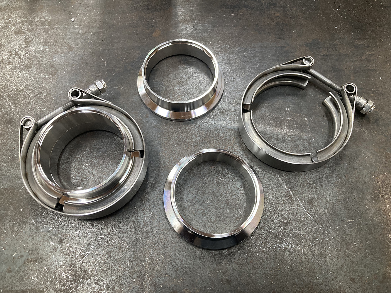
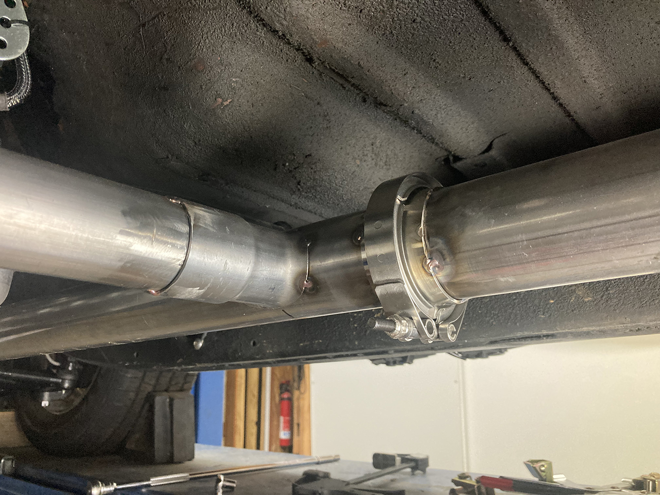
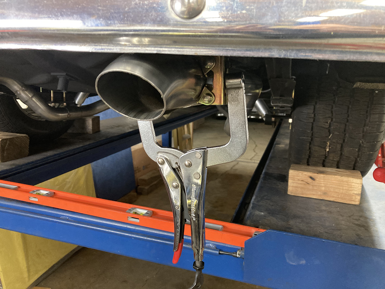
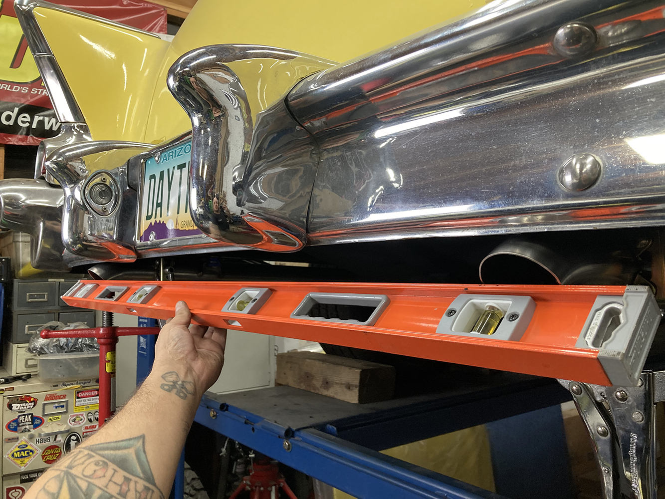
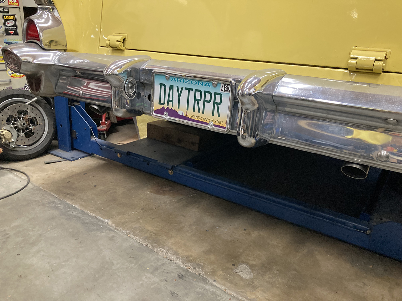
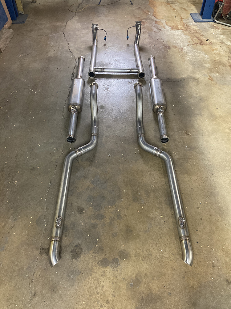
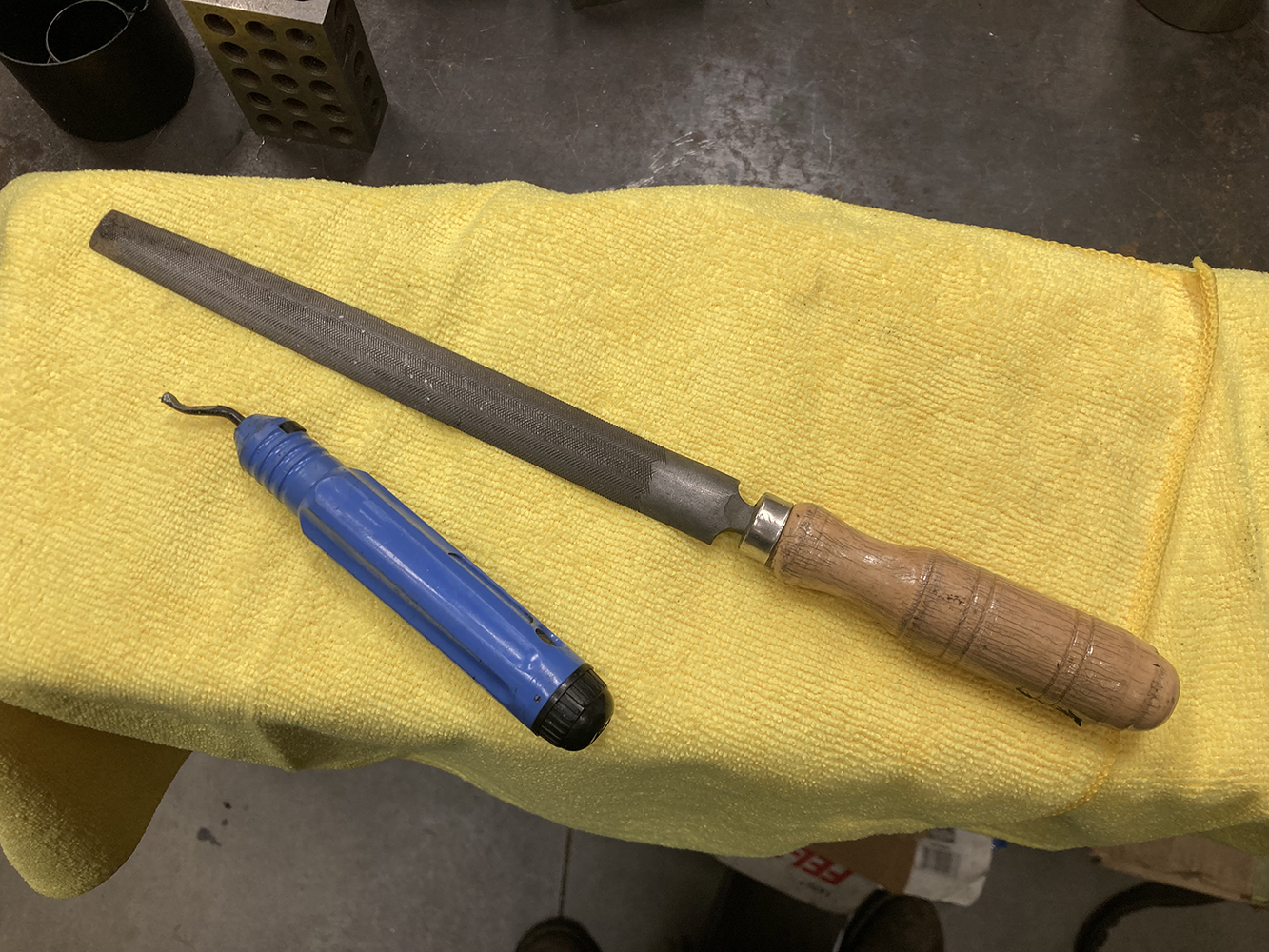
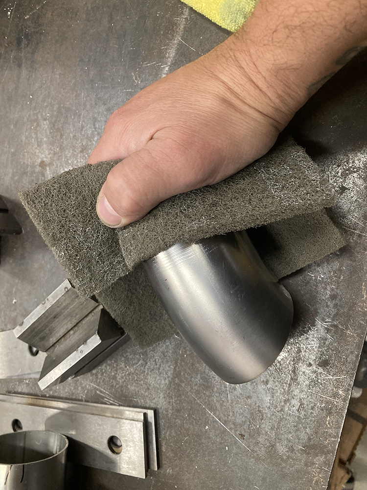
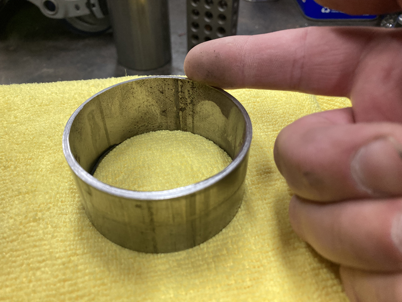
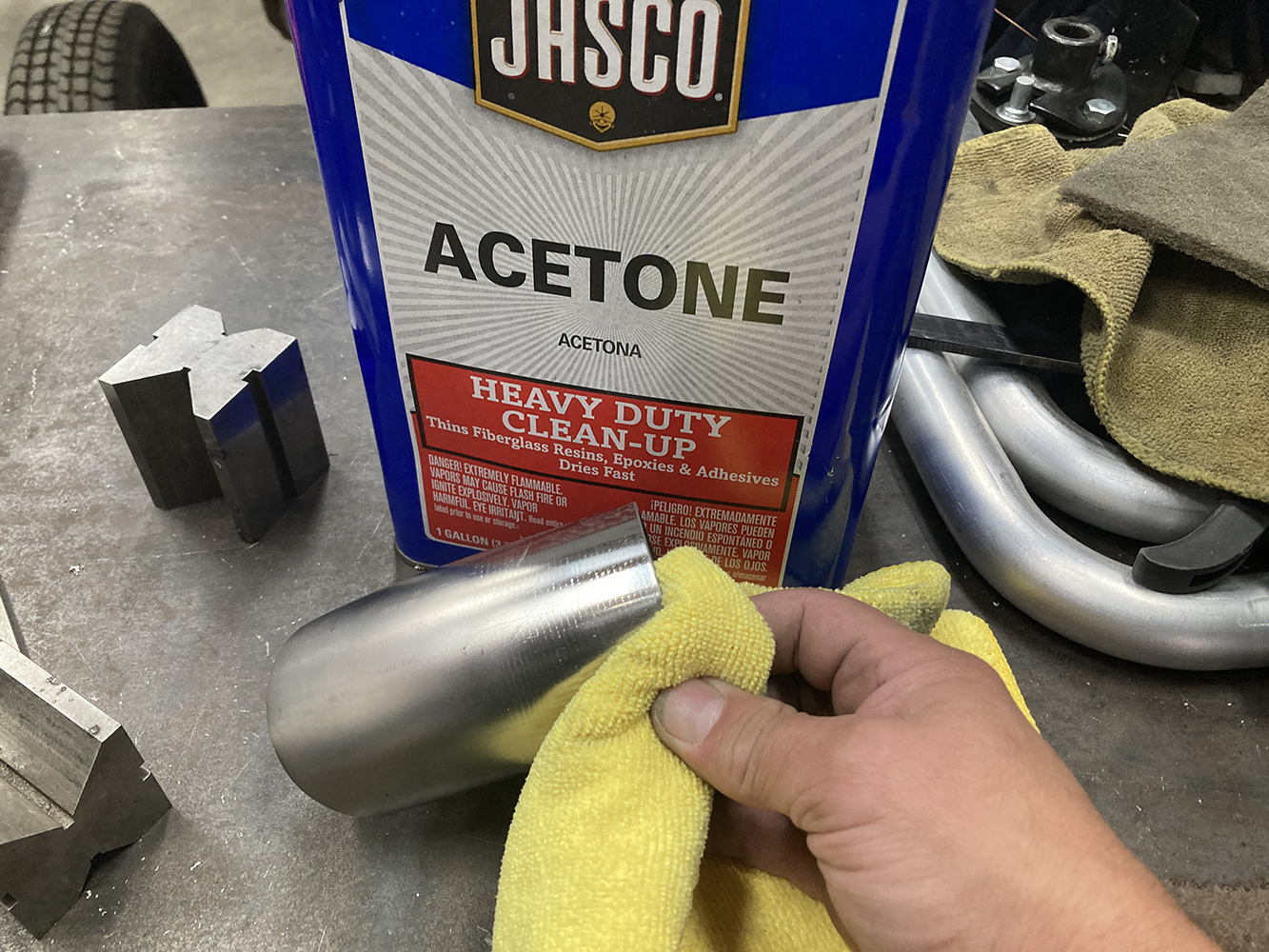
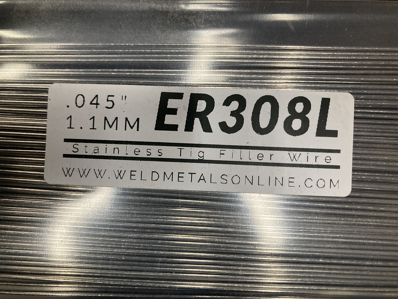
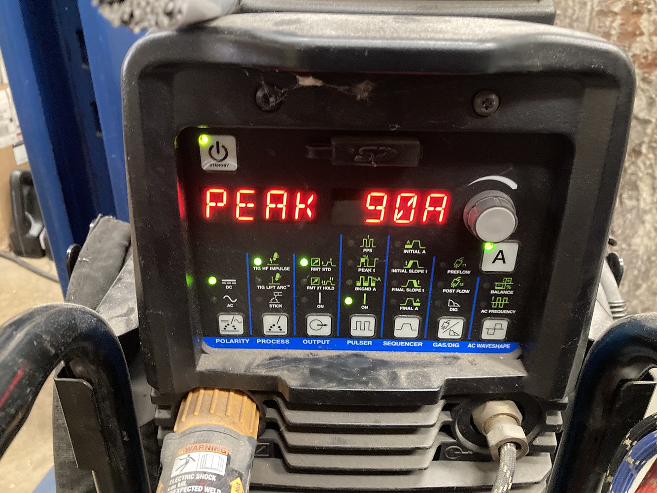
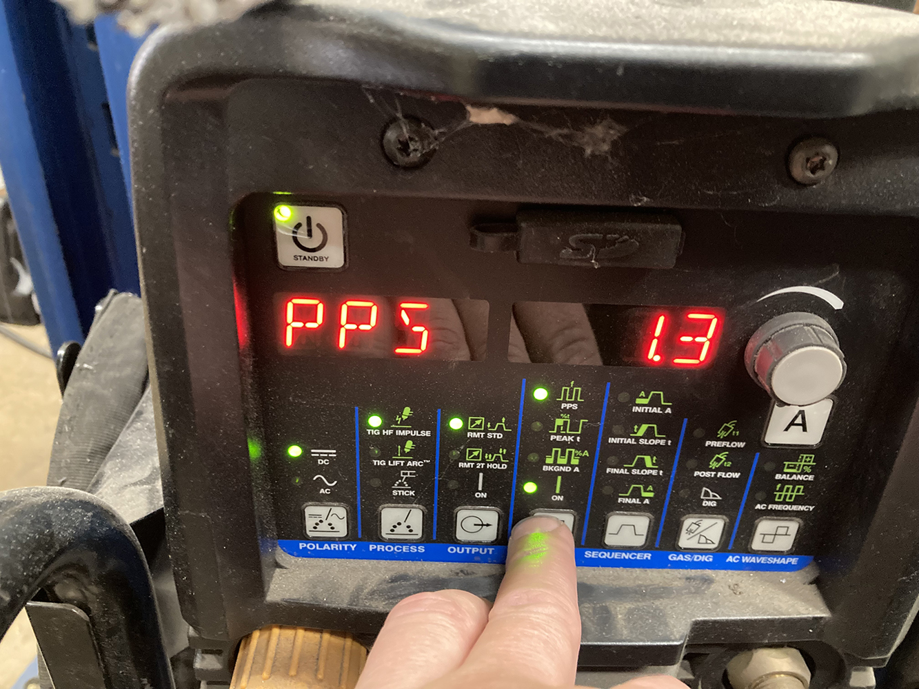
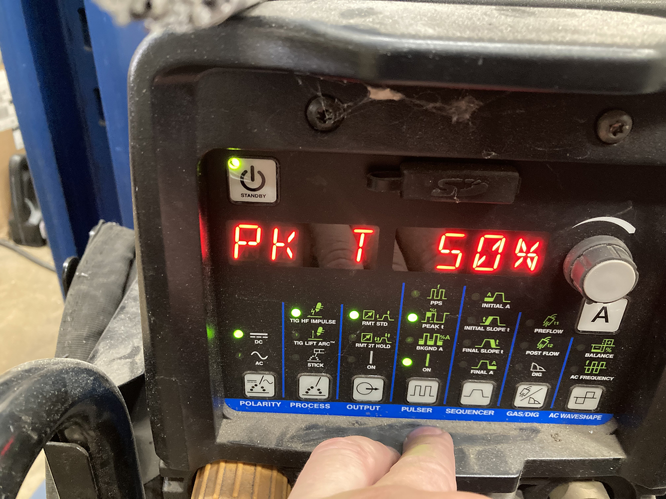
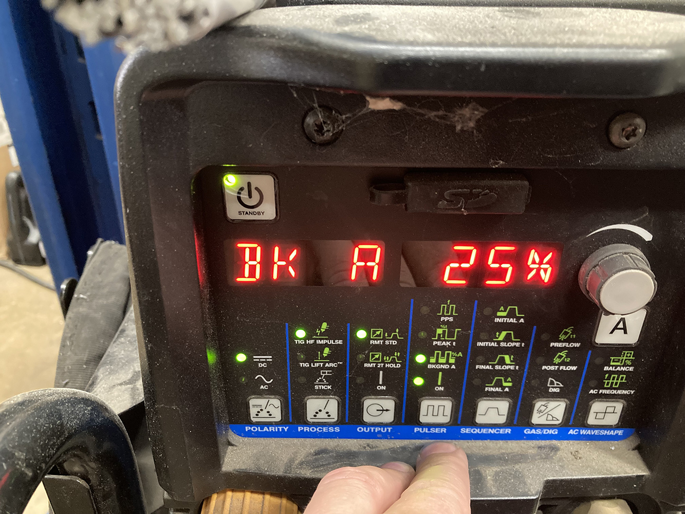
The exhaust is then reinstalled and the length of the straight section can be determined, trimmed, and installed. It was also decided at this point to trim the straight sections just aft of the H-pipe, using this section as the first joint in the system. This will allow the exhaust to be removed in sections if any maintenance is required.Stainless steel V-Band Clamps from Summit Racing (PN SUM-694250) will be used at every joint on our exhaust to provide a leak-free union that is easy to assemble and disassemble.Here’s the first V-Band Clamp in place.At this point, it was time to finalize placement of the mufflers. A decent location in which to attach a mounting tab is one of a few factors as to where to place each muffler. Relation to the passenger compartment is another. We’ve found that locating the mufflers aft of the front seat reduces drone and unwanted exhaust noise from penetrating the interior of most vehicles. Note the fitment made possible from the Super HP-2 muffler’s compact size, close but not against the floor, while still well above the bottom of the framerail making ground clearance a non-issue.Keeping things nice and level on the bench while tack and final welding is key.Due to the extremely tight confines between the wagon’s gas tank and the 9-inch Ford rearend, it was decided to run the exhaust under the axle. Not only does the exhaust need to route around the rearend in this area, but it also needs to flare outward in order to clear the tank and trunk floor.This was a challenging section to fabricate as we had to deal with multiple different angles, but by supporting each section independently and taking multiple measurements, we were able to assemble two symmetrical sections that provide plenty of clearance to the suspension components while still maintaining plenty of ground clearance.A short section taken from a bend is used as an exhaust tip, tucked in nice and tight against the bumper.Eye-balling the location of each is possible, but a 4-foot level ensures they end up at the same height and length relative to the vehicle.Another V-Band union was added just aft of the muffler, while an additional exhaust mount was also placed near the end of the exhaust.The angle-cut turndown tips make for a lowkey exit of the exhaust.With the exhaust tacked together, each section is placed on a welding bench and fully TIG welded. Here, the five separate sections are ready for final installation.Whatever method you’re using to cut your tubing, there’s going to be some cleanup involved to get rid of the swarf left behind. We’ve found a half-round file and a deburring tool handles nearly all of this.Cleaning up the area to be welded starts with a scuff using a gray Scotch-Brite pad. This results in a clean, shiny surface, removing most impurities and oxides.The inside of the tubing needs to be treated to the same cleaning methods as the outside. A fully penetrating weld will pull any impurities inside the tubing up into the weld creating an unacceptable weld.After both the inside and outside have been scrubbed clean using the Scotch-Brite pad, both surfaces are wiped down with Acetone to further clean the surface of any oil, grease, or other impurities.While we’re at it, might as well wipe down a couple lengths of welding rod to ensure they’re nice and clean as well. For this job, we’re using ER308L stainless TIG filler wire in 0.045-inch diameter.Our go-to TIG welder is a Miller Dynasty 210. This inverter machine can handle everything from the thinnest of sheetmetal repairs to chassis fabrication, aluminum, and stainless steel welding. For this job, we’ll be welding in the DC setting using the pulse feature of the machine. Using some scrap material, we’ve found that a pulse setting with a peak of 90 amps, a pulse-per-second of 1.3, 50 percent peak time, and a background amp setting of 25 percent produced the results we were looking for with a fairly small-heat-affected zone and a decent travel time.
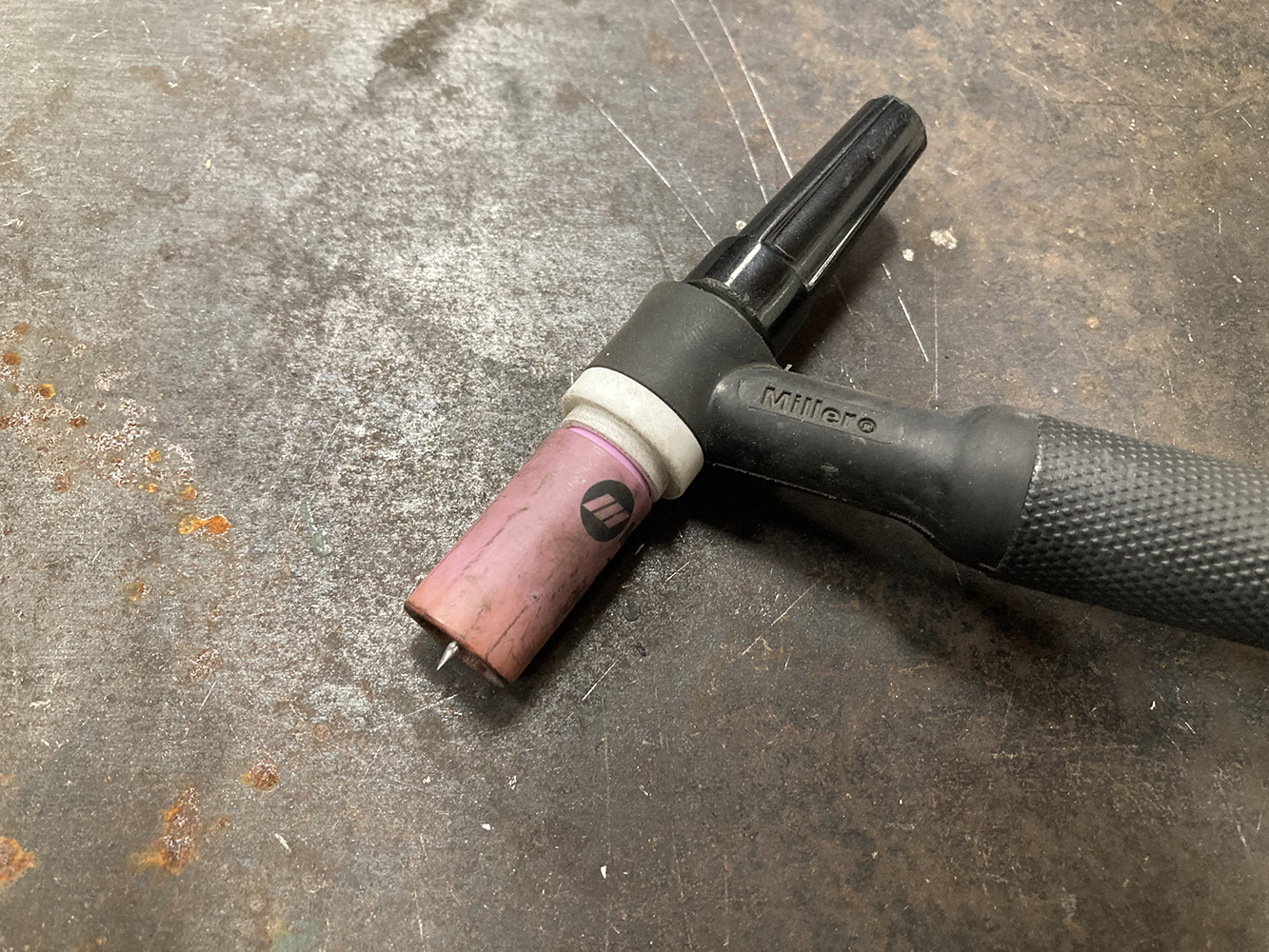
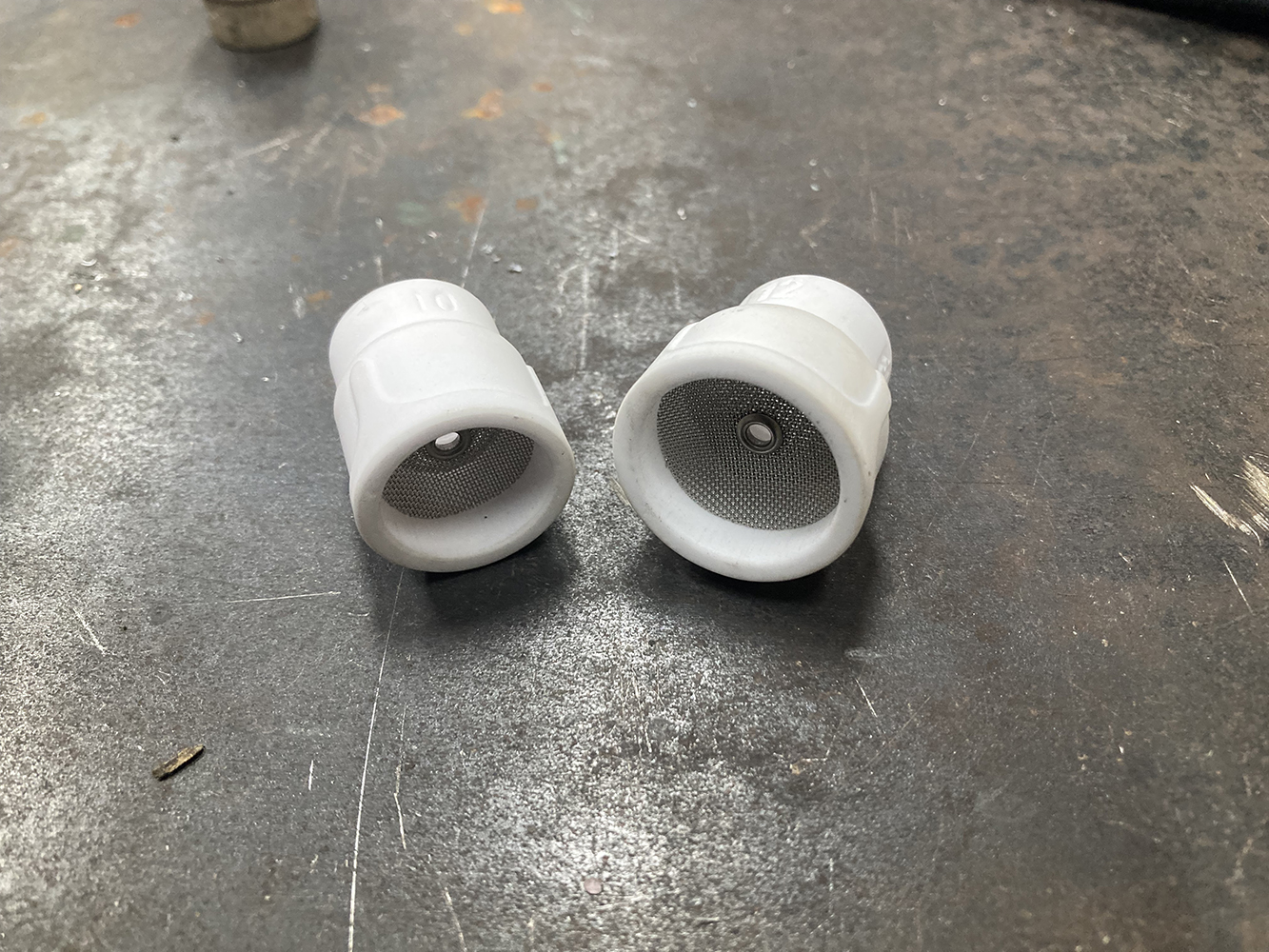
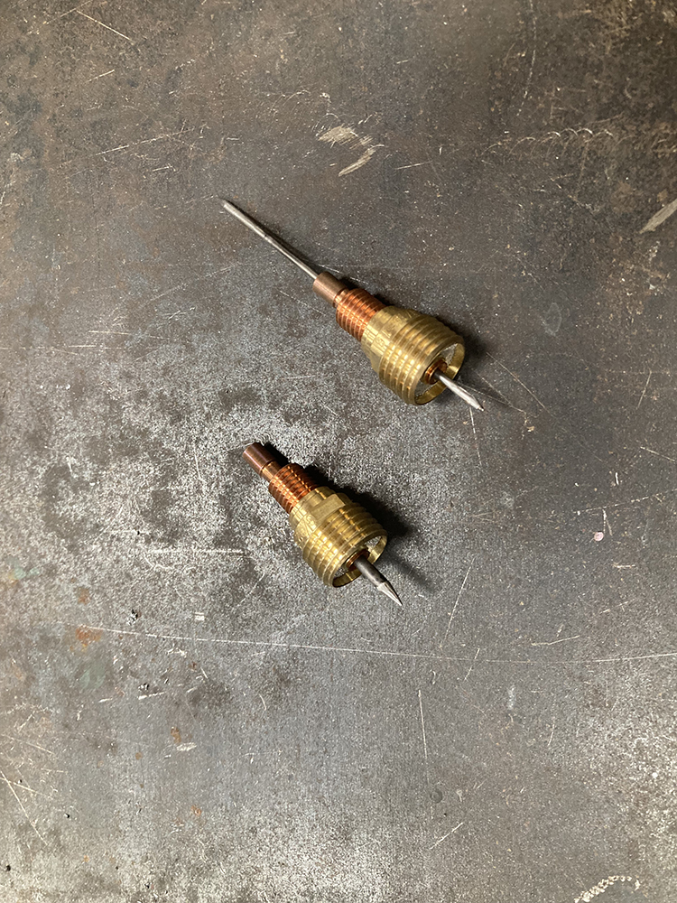
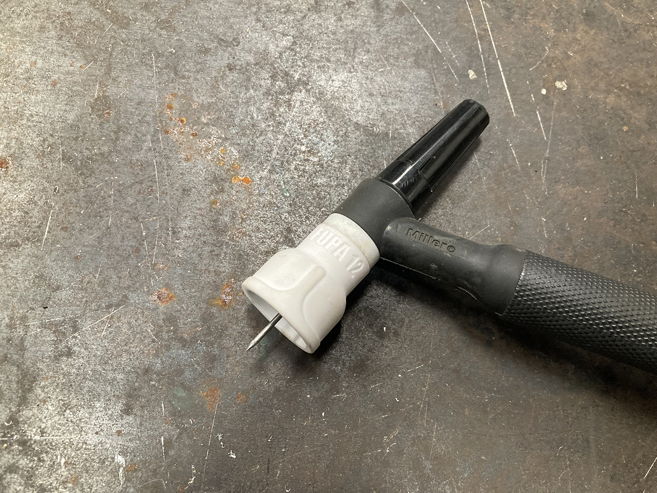
The stock TIG torch on our Dynasty machine came with a fairly small #7 (7/16-inch) nozzle. For mild steel, this setup works fine, given the amount of gas coverage typically required.Stainless steel however, likes a larger area of gas coverage, so we’ve found that a #10 or #12 gas diffuser lens, such as these Fupa units, produce a really nice weld. The larger cup size allows for increased stickout, which results in easier access to tight corners and gives the user a clear, unobstructed view of the weld pool, while the diffuser gas lens allows for higher-cfm gas flow for increased coverage with reduced turbulence.
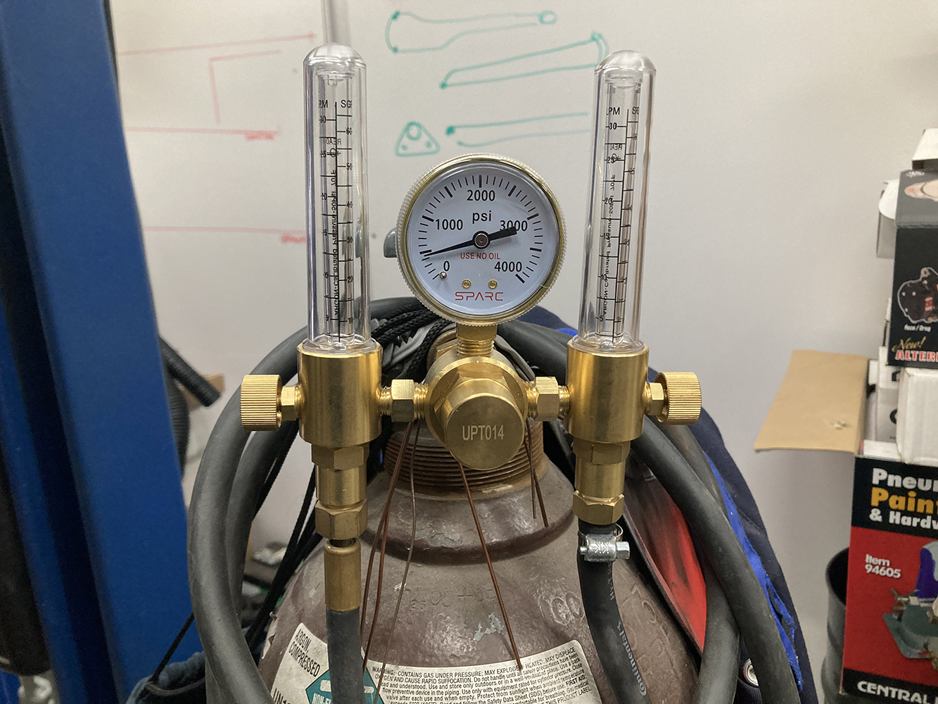
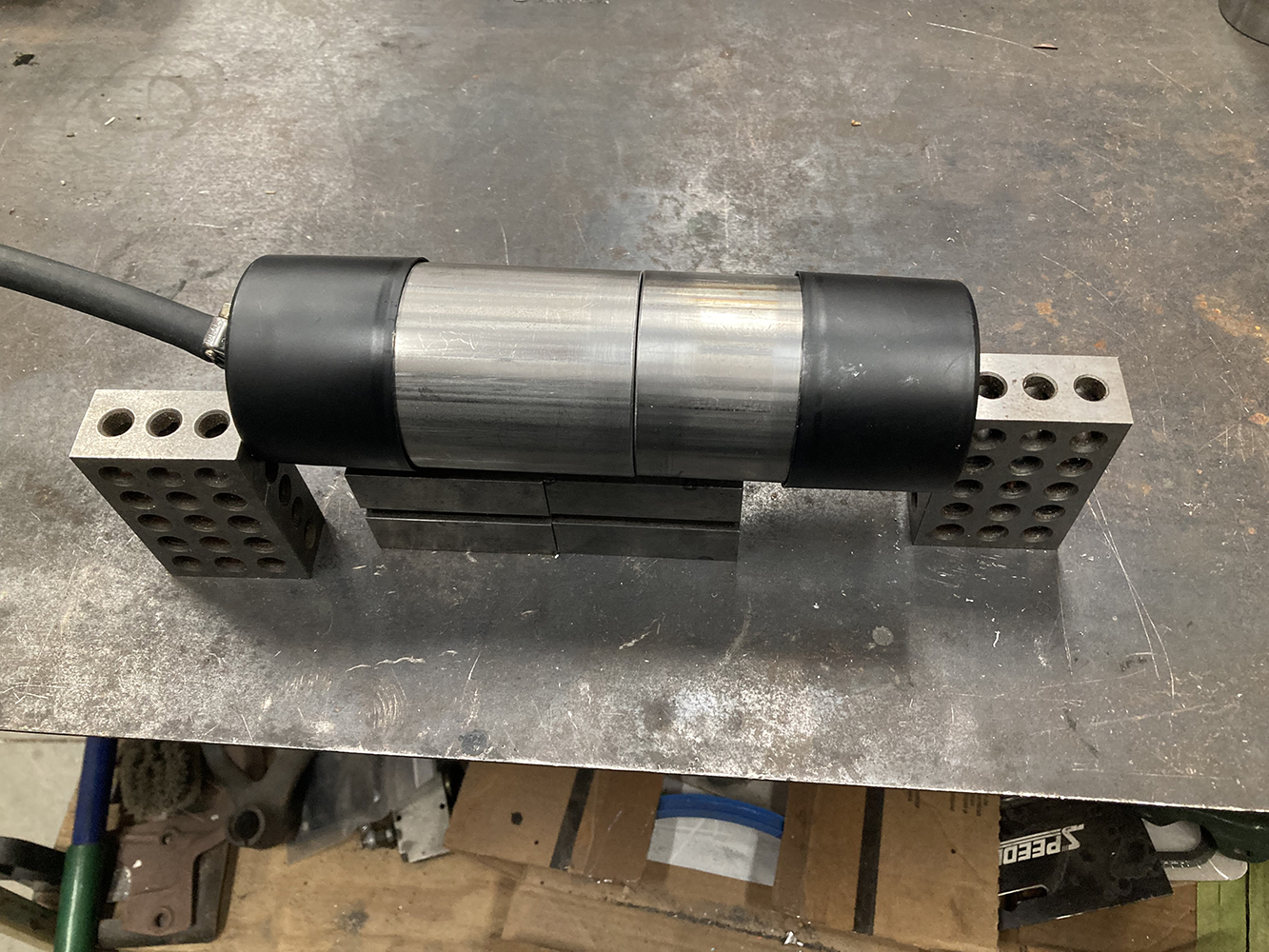
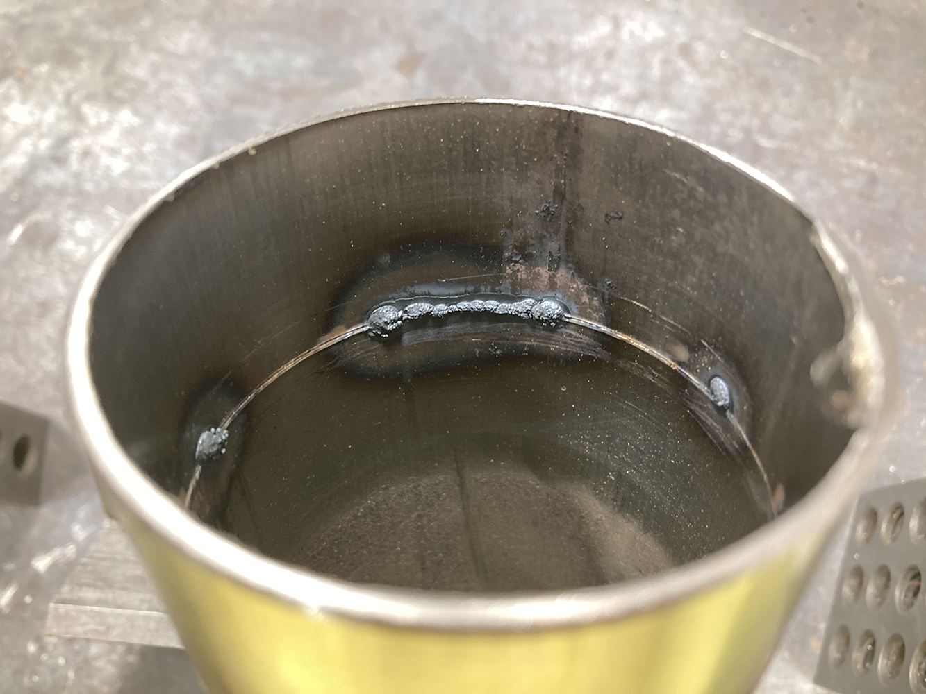
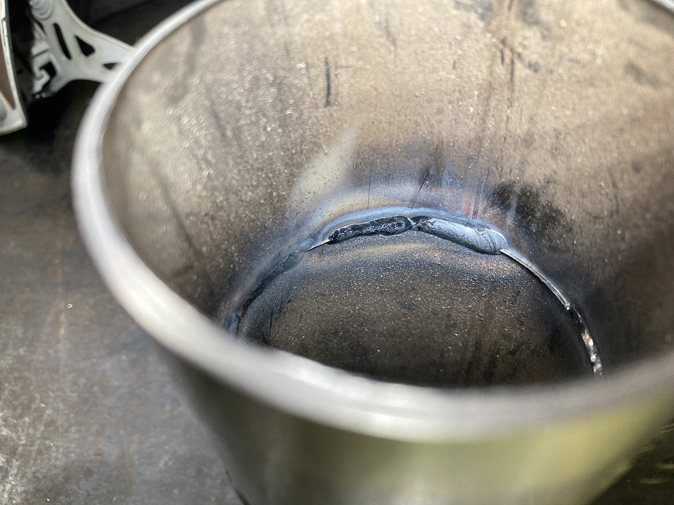
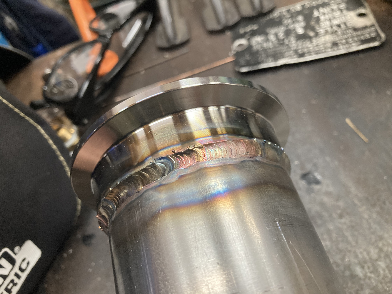
Speaking of gas flow, when welding stainless steel tubing, it’s necessary to back purge to maintain the purity and cleanliness on the inside of the tubing or backside of weld. This is achieved by purging the interior of the tube with Argon gas, preventing contamination from developing during the welding process. The result is a stronger, fully penetrated weld that isn’t prone to failure and cracking. This Dual-Output Argon Flow Meter from Sparc is perfect for back-purging since its dual-adjustability allows for the gas flow to the torch and the back purging source to be set individually.When back purging a section of tubing, we try to keep the size of the vessel as small as possible, resulting in less waste of Argon gas. When welding up a large section of tubing, such as a long straight section of exhaust, this can get tricky. Since Argon is heavier than Oxygen, the purge side is usually the lowest point of the section, with the highest point given a small bleed hole for the Argon to push the Oxygen out. Similar to bleeding the air out of a brake system.The inside of this weld illustrates why it’s important to back purge. Here, we have what’s commonly referred to as “sugaring.” This is essentially a contaminated back side of the weld. Penetration is questionable, prone to cracking, and typically unacceptable.Compared to a section of weld that has been accomplished using the back purge method, we can see a clean weld with sufficient penetration.The resulting TIG weld should look something like this, with fairly consistent bead lengths, full coverage, and an even heat-affected zone.
We use cookies to ensure that we give you the best experience on our website. If you continue to use this site we will assume that you are happy with it.