Plumbing a fuel system on a new build or after an engine swap can be a daunting experience to the uninitiated, but with a little help from your friends here at All Chevy Performance the task can be simplified so that anyone with a handful of the proper tools can get the job done right. But, plumbing the fuel system on a ’69 Camaro back in 1969 is a totally different affair than the way we’d prefer it to be done today. New methods and materials have introduced a modern modus operandi when it comes to the fuel system in general. That first-gen Camaro relied on gravity and suction to feed the mechanical pump mounted off the side of its small-block engine, feeding less than 10 psi to the carburetor. A steel hard line running fore and aft connected by some low-pressure rubber hose and a couple hose clamps were all that was required. Filters, regulators, and return lines were non-existent for the most part—that is until electronic fuel injection came into vogue about 30 years later.
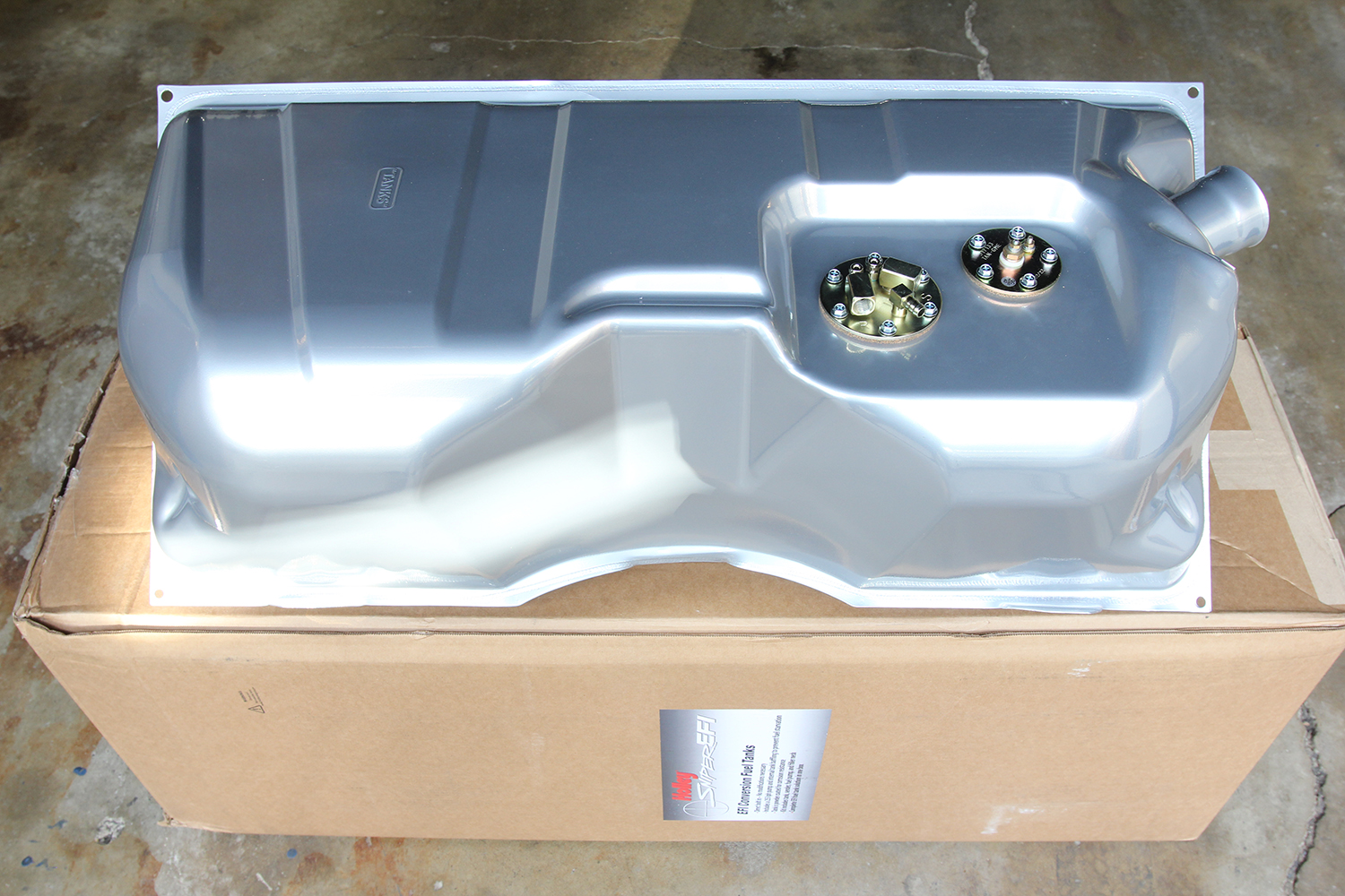
A new Sniper EFI fuel tank from Holley (PN 19-191) is where the fuel system starts on Bruce Valley’s 1957 wagon. Designed as a direct replacement for the stock unit, Sniper EFI fuel tanks come equipped with a 255-lph fuel pump with built-in baffling to prevent fuel sloshing and starvation. Constructed from galvanized steel, each tank is then powdercoated silver for protection and appearance. In addition to the fuel pump assembly is a fuel lever sender with the correct OE ohm range, drain plug, and new tank straps.
With the advent of bolt-on fuel injection systems and crate engines utilizing OE injection systems, today’s fuel system requirements look a little bit different. For starters, the pressure has increased by about 50 pounds. This requires different hose and fittings, at the very least. In addition to the increase in pressure, EFI requires very clean fuel and responds very poorly to any contaminants contained within. That increase in pressure also needs to remain constant, as any drop can result in poor performance. Careful filtering and regulating therefore is a must in EFI systems. An increase in pressure also requires a more dependable fitting than the venerable barb fitting and hose clamp. A fitting that doesn’t require constant attention and won’t come loose and leak is mandatory. The result is the adoption of specialized hose and hose ends that are assembled to suit and use the AN system.
The AN system was established during World War II between the Army Air Corps and the Navy (AN) to develop a joint standard fitting system used to connect flexible hose to rigid metal tubing using a 35-degree flare, a female tube nut and sleeve, mated to a corresponding male fitting. Sizing is noted by 16ths of an inch for each number (AN-6 = 6/16 or 3/8 inch). The ease of creating a leakproof seal due to the simplicity of forming a single 35-degree flare, makes the AN system very attractive to car builders and the military alike.
When it comes to fluid plumbing, be it brake, fuel, coolant, or transmission fluid, in the Clampdown Competition shop, AN is the only way to go. It’s simple to form and the availability of a myriad of fitting combinations beats the old barb and clamp fittings with a large-sized hammer. The reliability of an assembled fitting is also very attractive to the builder whose work may go off to parts unknown, never to be checked again.
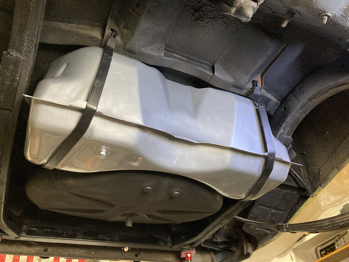
Like many vintage vehicles, the gas tank in our buddy Bruce Valley’s 1957 Chevy Handyman wagon was in great shape, but it lacked the requirements of a modern EFI-equipped engine. A single outlet built into the sending unit wasn’t going to cut it when it came time to feed the fuel requirements of the LS3 that we’d previously swapped in the wagon. No provision for a return was another problem, and we certainly did not want to mount the fuel pump on the framerail as that results in a noisy pump and the ambient heat underneath the vehicle tends to shorten the life of said pump as well. Our best option was to swap the stock tank with a new one that was equipped to handle modern EFI. With that as our starting point, we set out to build a fuel system that will provide years of reliable operation with minimal maintenance.
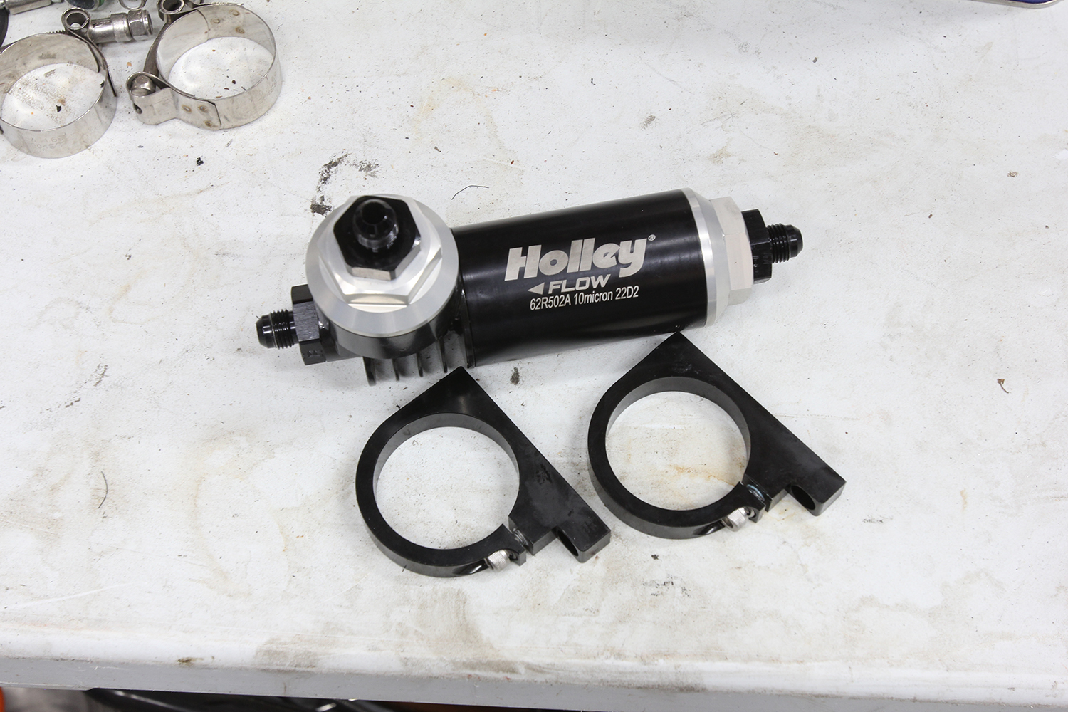
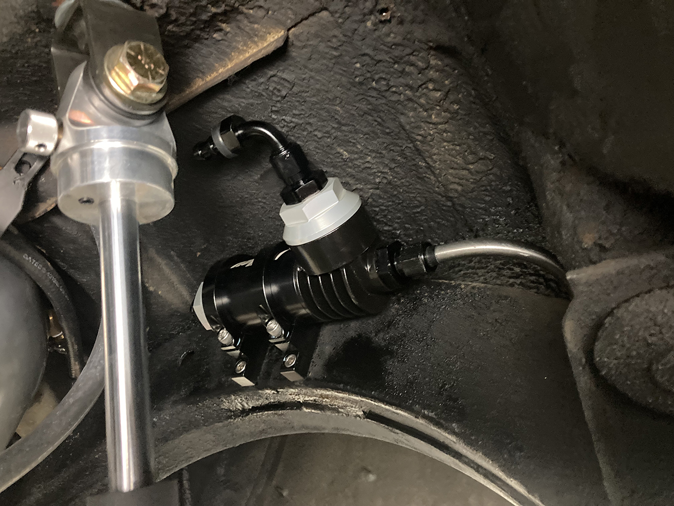
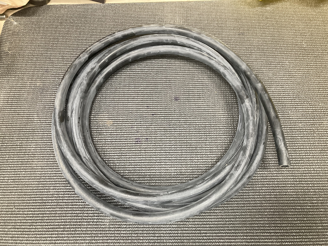
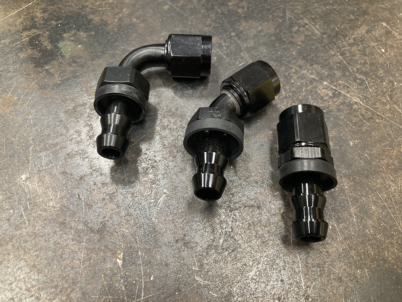
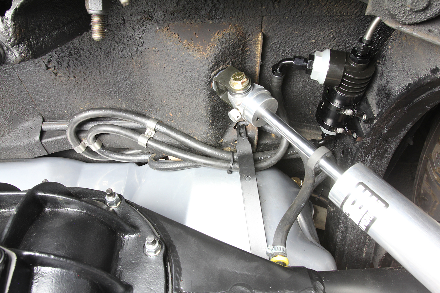
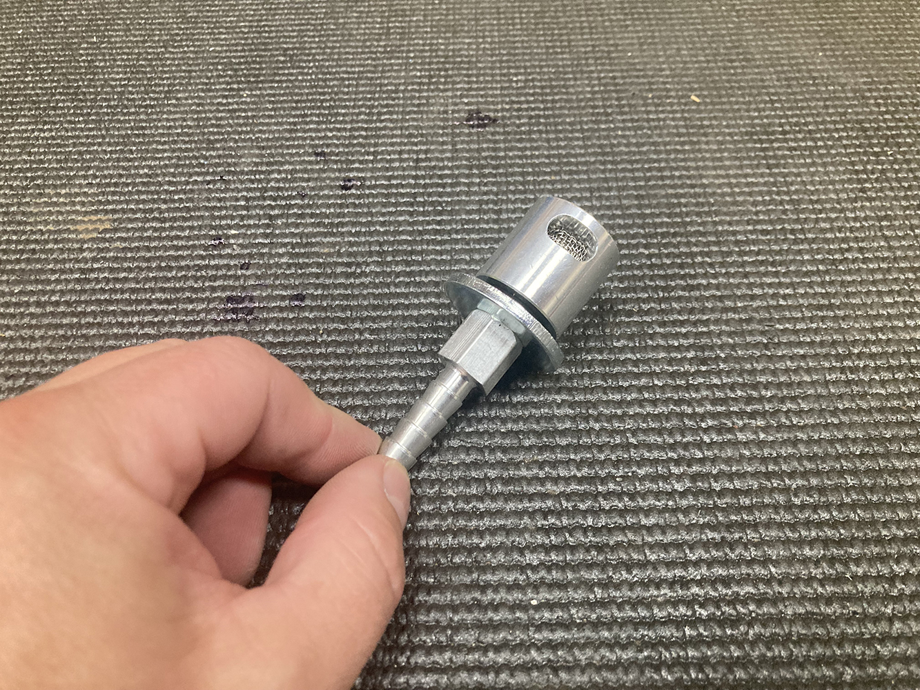
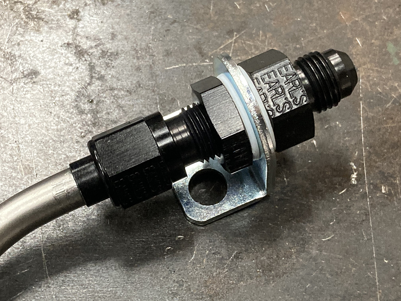
With the fuel pump installed in the gas tank, the only external part needed in our install is this Holley EFI Regulator assembly (PN 12-889), preset to 59.5 psi, which features a built-in 10-micron filter.Holley’s EFI Regulator is designed to be mounted near the fuel tank, making the return line much shorter than the typical pass-through EFI setup.When it comes to the flexible hose portion of our fuel system, we’ll be using AN-6 size (3/8-inch) Earl’s Super Stock Push-On Hose (PN 780006ERL) and an assortment of their corresponding hose ends.
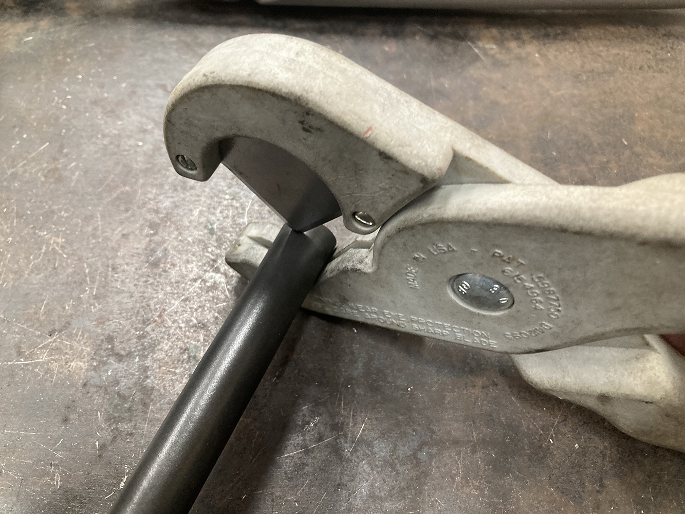
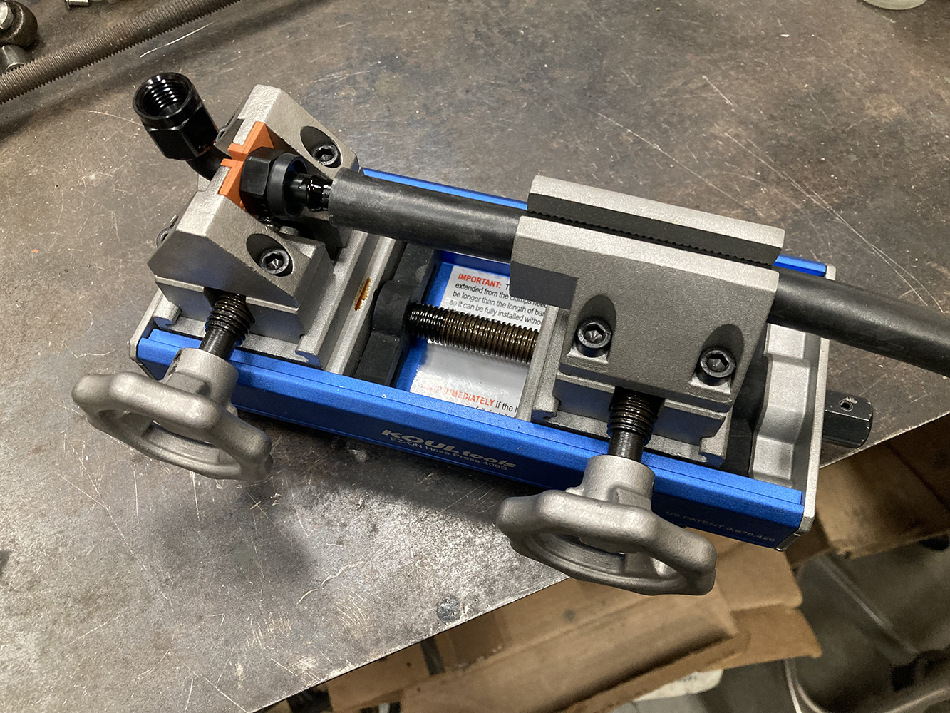
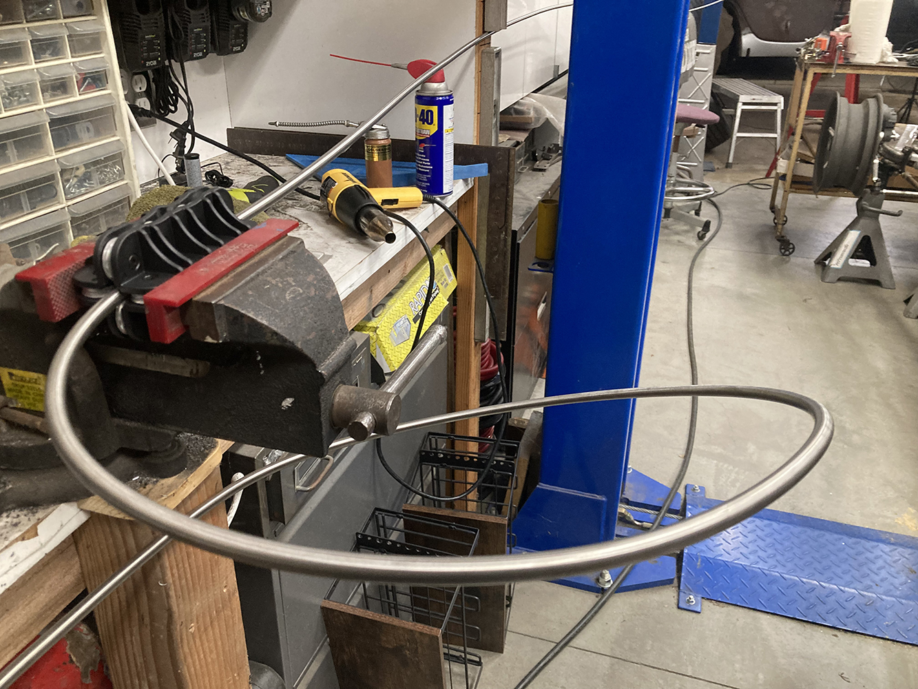
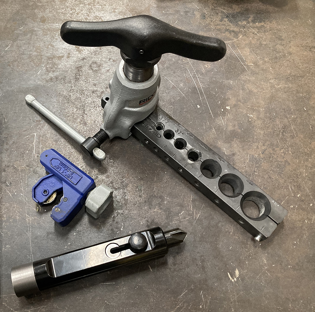
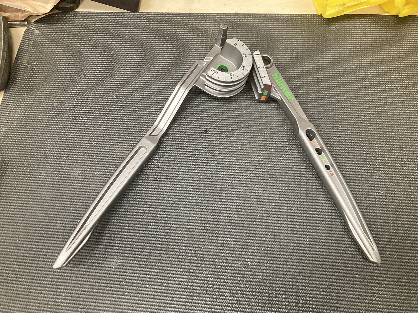
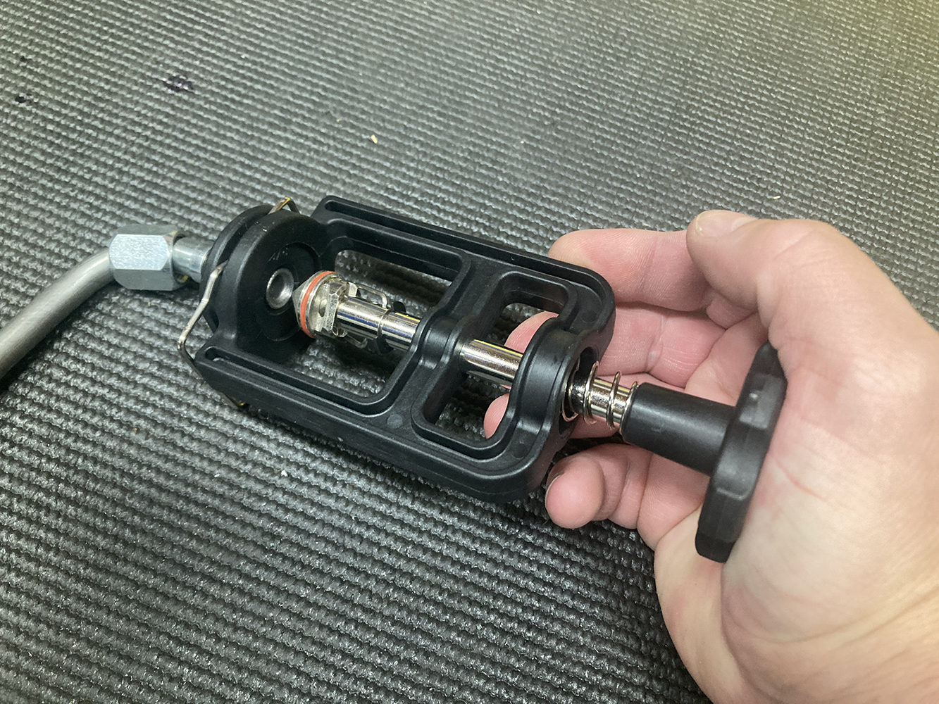
It’s important to get a straight, clean cut using a purpose-built tool for push-on hose assemblies. Scissors or a dull razor blade won’t cut it.I’ve fought push-on hose assemblies in the past, but after purchasing an EZ-ON Hose Press from Koul Tools (PN Model 426), that battle is over. The EZ-ON Hose Press securely holds the hose end in place while the hose is installed via the traveling carriage.We installed the vent hose, return, and outlet lines first before the tank was raised into place. Each line was then routed, trimmed to fit, and assembled with the corresponding hose end. The outlet or feed hose is attached to the rear of the regulator while the return exits the side and runs back to the top of the tank. The hard line that is attached to the front of the regulator is the outlet and will continue forward along the framerail.The vent hose is routed along the filler neck and terminates near the filler cap to a rollover protected vent.We’re going to keep the soft lines down to a minimum with the majority of the plumbing handled by 3/8-inch stainless steel hard line, which we ordered from Summit Racing (PN SUM-220298-25X). A 25-foot roll will take a little bit of straightening in order to make those long runs down the 1957’s framerail, so we also ordered a handheld tubing straightener from Summit Racing (PN TTN-85563) to give us a hand with this task.A couple more tools that we’ll be using to fab up the hardlines are a sharp tubing cutter, a 37-degree AN flaring tool, a deburring tool, and a tubing bender.
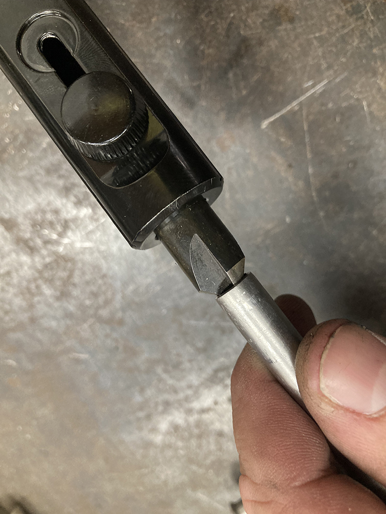
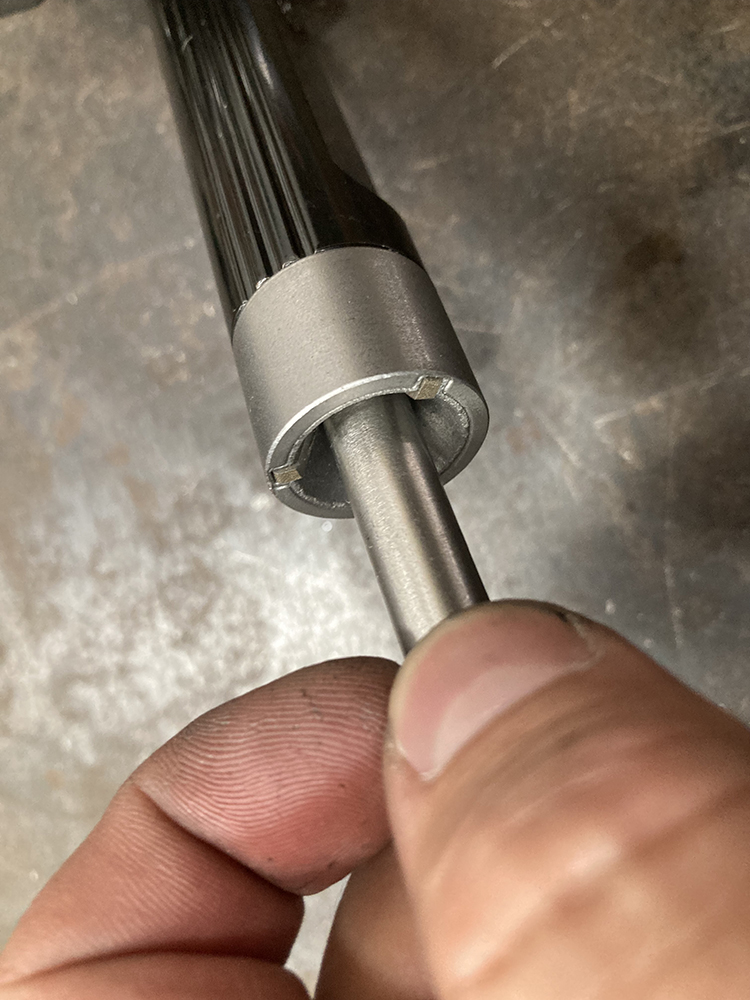
We’re using AN fittings throughout our fuel system, so that means we’ll need to make a 37-degree flare on the end of each piece of tubing in conjunction with a nut and sleeve. First things first, we need to cut our line to length using a tubing cutter.Next, both the id and the od of the tube is lapped using a deburring tool.
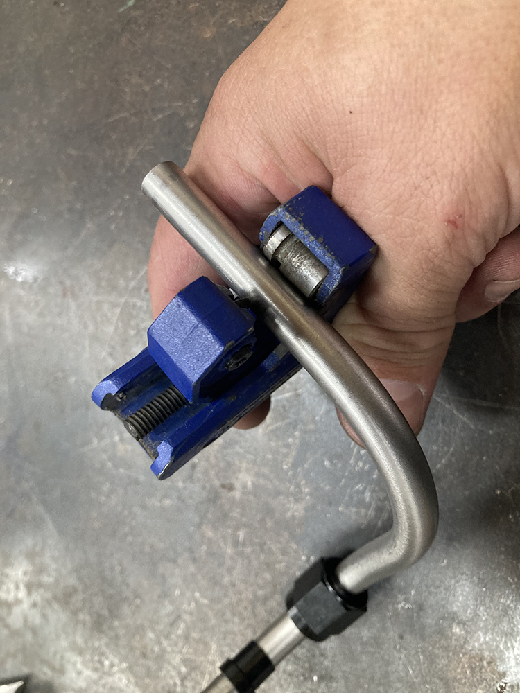
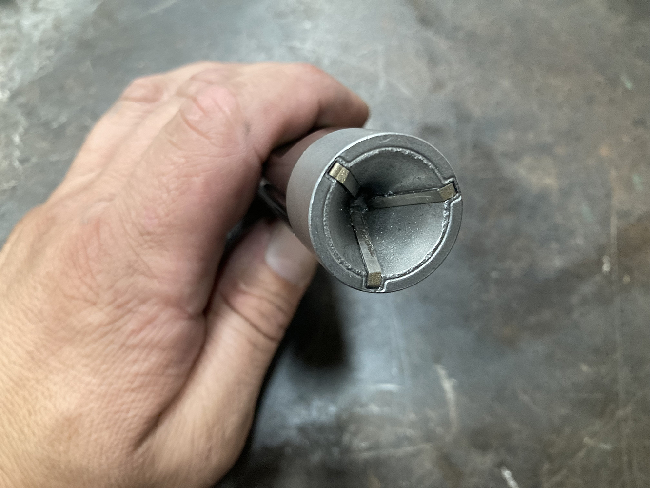
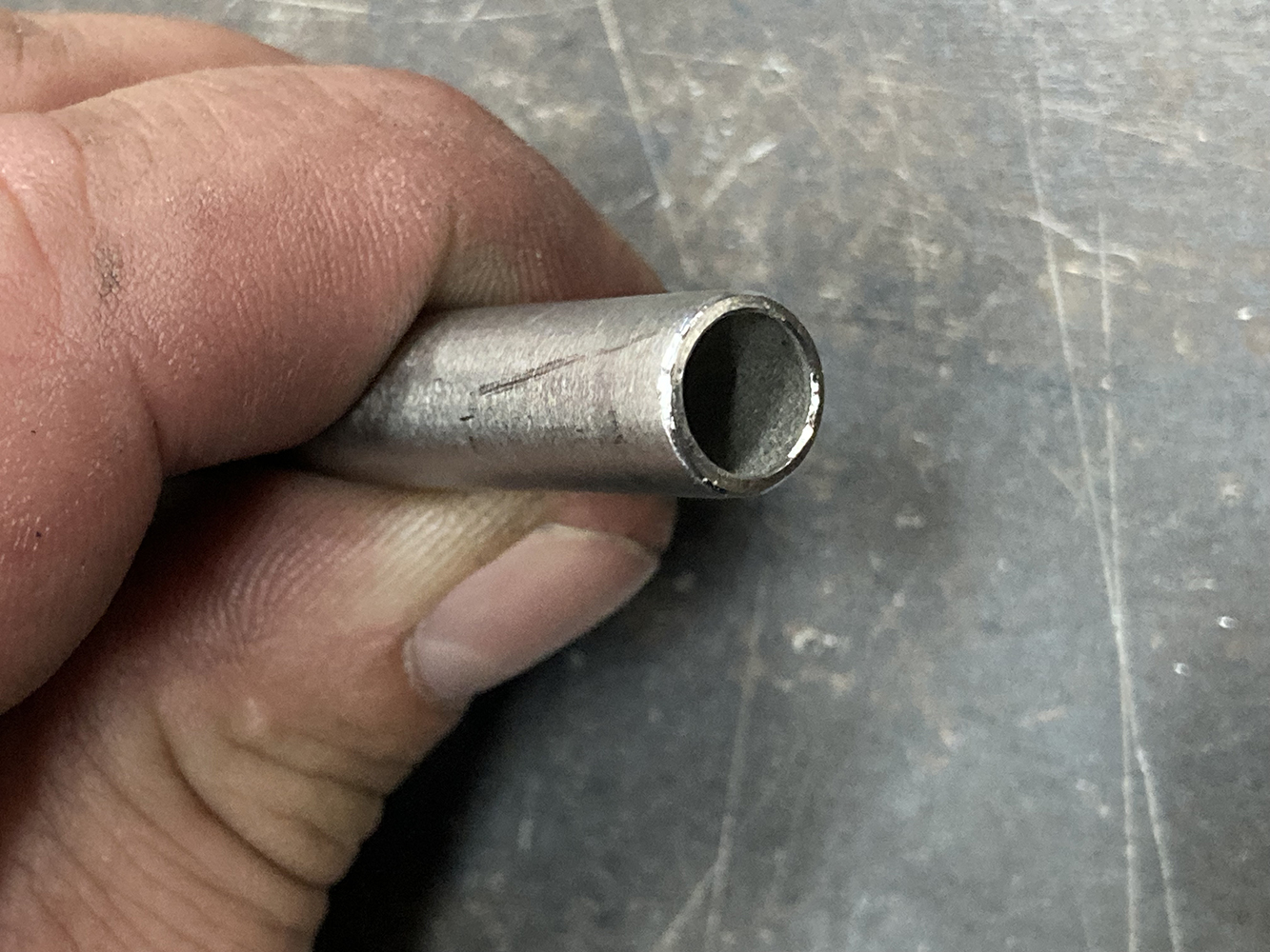
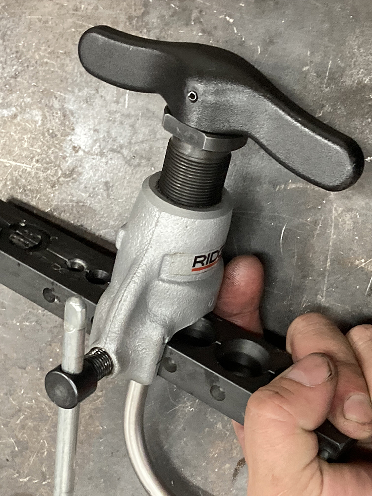
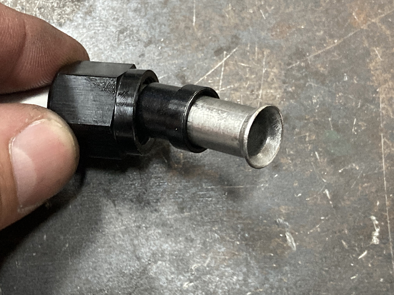
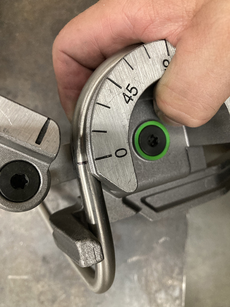
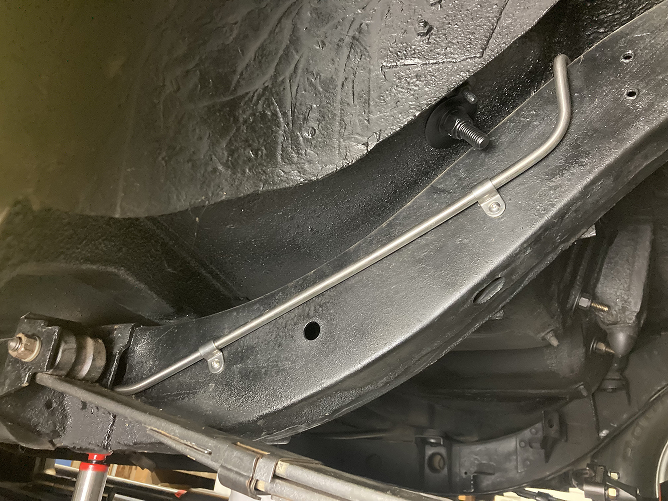
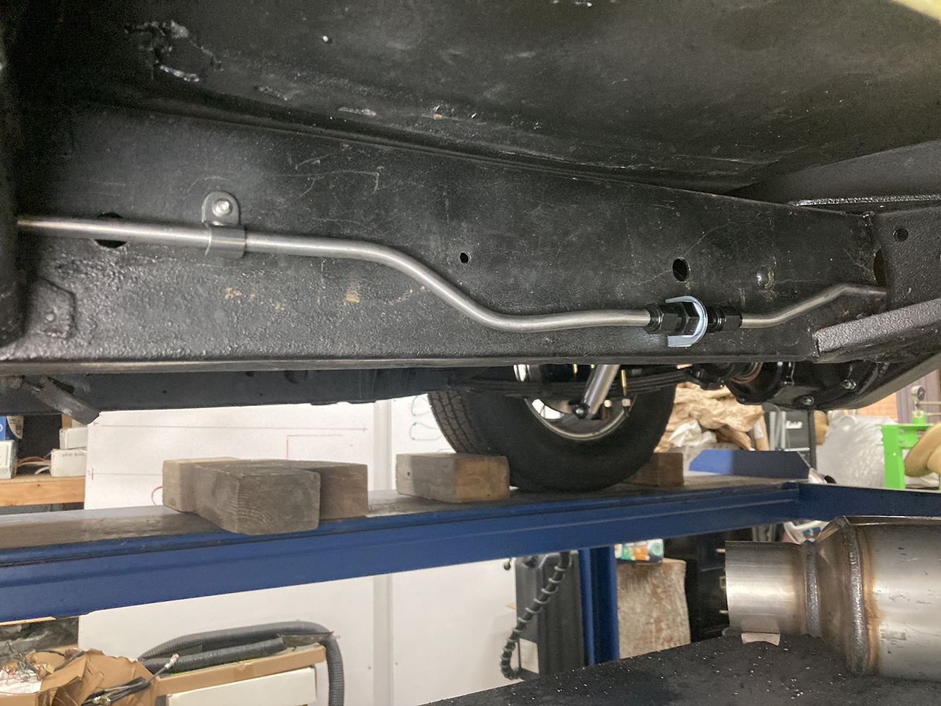
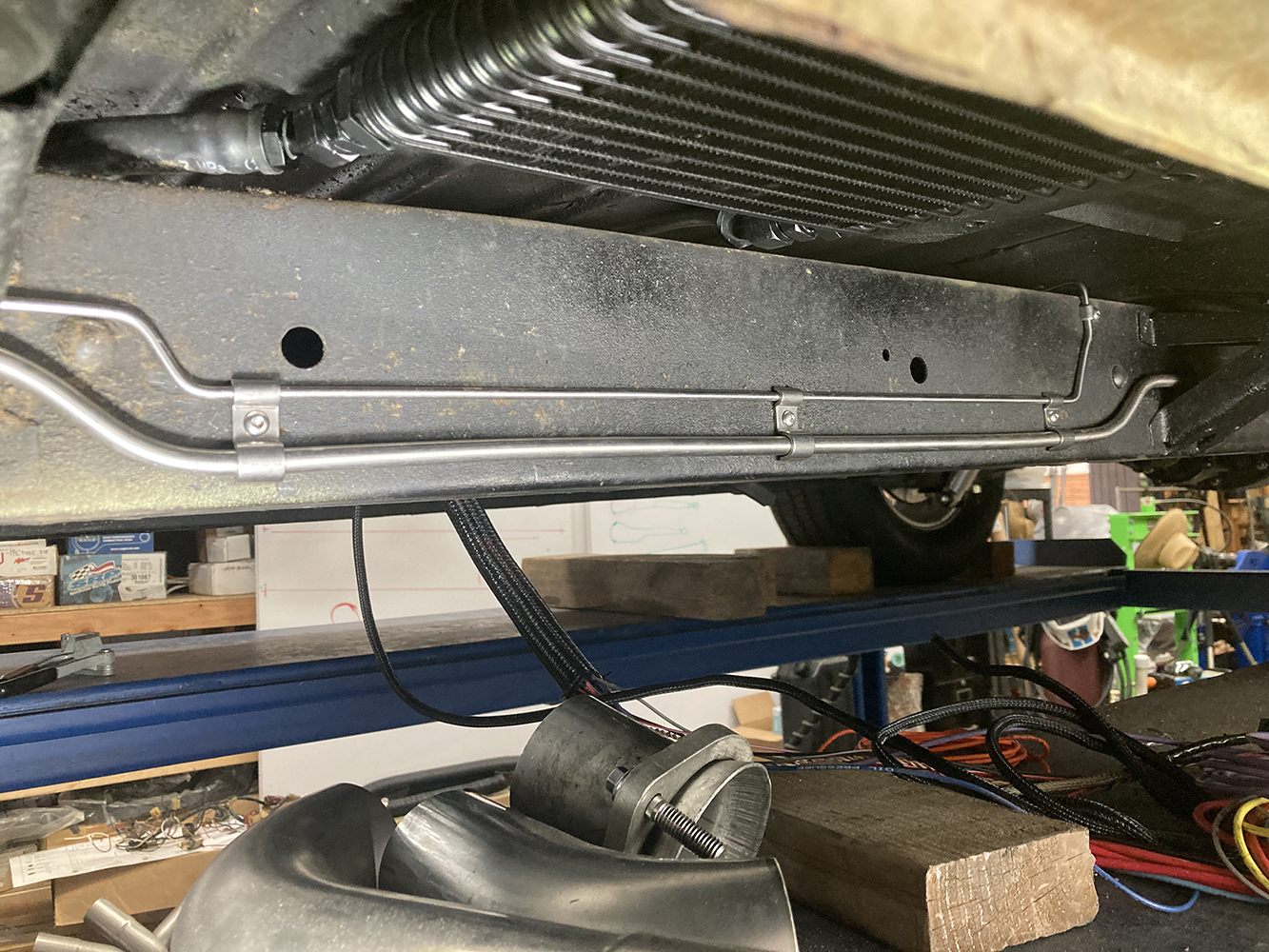
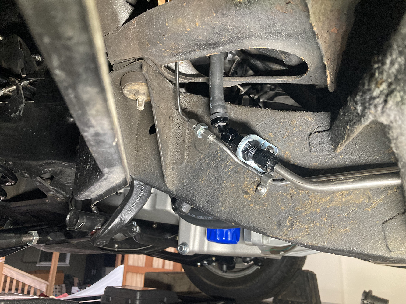
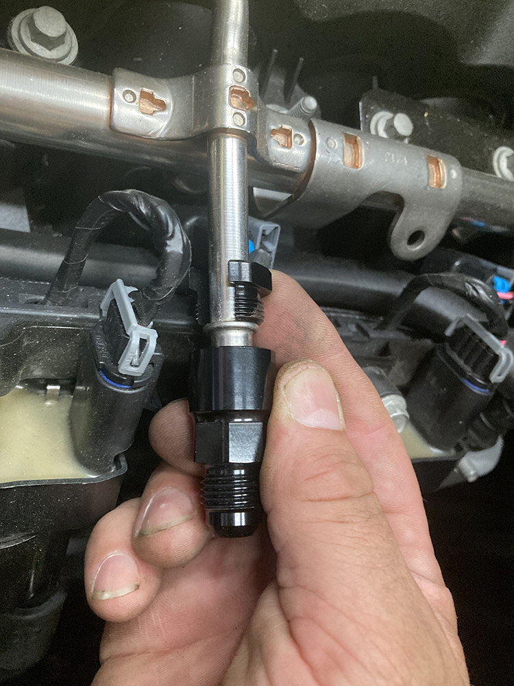
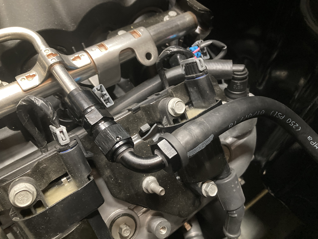
With the end nice and square and free of any burrs, it’s time to form the 37-degree flare using our handheld flaring tool.The business end of our connection shows the relationship between the nut and sleeve and the flared end of the tubing.Here’s another neat tool from the guys at Koul Tools; this is their Surseat Flare Lapping Tool (PN P-51B). Using this tool after a flare is created or on existing tubing that’s been previously flared, ensures a leak-free joint by lapping the flare to perfection.Once assembled, the tube nut sandwiches the female flare between the tube sleeve and a matching male flared fitting.Forming hard lines can be a work of art or a source of great frustration. One tip that I’ve found is to pay attention to the bend radius of the bending tool you’re using. This allows accurate bends to be made, no matter the direction of travel. By marking the tube where the bend needs to “end” (i.e. up and around a body mount) and subtracting the radius from the mark, that change in direction will land exactly where you want it.This process makes snaking hard line through tight sections a little easier as everything can be marked exactly where each bend needs to land. Clamps every 6 to 8 inches ensure the line is securely fastened and won’t vibrate or come into any unwanted contact.Sometimes, a length of hard line becomes too unruly to manage as one piece due to any number of factors. Here, a bulkhead fitting is used to join two sections of hard line, easing installation. Note the bulkhead fitting is attached to the frame using a clamp.As the fuel line travels forward, it’s joined by its cousin, the brake line. Here, we’re using a couple double line clamps from Kugel Komponents to secure all that stainless.At the bottom of the firewall, it was decided to terminate the hard line at another bulkhead fitting and continue the journey using another section of Earl’s Super Stock hose and fittings up the firewall and to the engine.The LS3 crate engine that’s in Bruce’s ’57 requires a special, quick disconnect fitting from Earl’s (PN AT991986ERL) to adapt it to an AN hose end.The final piece of the puzzle, with the push-on hose terminating at the quick disconnect fitting on the engine’s fuel rail, and we’re one step closer to breathing life into the LS3.
We use cookies to ensure that we give you the best experience on our website. If you continue to use this site we will assume that you are happy with it.