Part 1: Avoid These Brake Fluid Blunders!
By Ron Ceridono – Photography By the Author, Brian Brennan & Courtesy of Wilwood, Classic Performance Products & Speedway Motors
Over the years, we’ve seen a number of brake system blunders that should and could have easily been avoided. Poor or problematic brake system performance can often be traced to the wrong combination of parts or faulty installations—and then there is a lack of maintenance. While most of us will check the brake fluid level in the master cylinder from time to time, it’s also essential to choose the correct brake fluid in the first place and change the fluid regularly.
Brake fluid standards are established by the Department of Transportation (DOT) regulations and among other things, indicate the fluid’s boiling point. This is important because as the brake system heats up, brake fluids with low boiling points begin to vaporize, and the pedal must travel further to apply the same amount of force on the brakes.
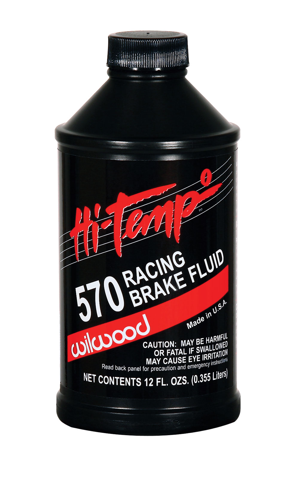
The most commonly used brake fluids are DOT 3, DOT 4, and DOT 5.1. All these are glycol-based fluids that are hygroscopic, which means they absorb water and hold it in suspension. As water has a direct impact on the boiling point of brake fluid, the DOT measures it on two separate scales: the dry boiling point is for a new, freshly opened container of unused fluid; the wet boiling point is after it has absorbed 3 percent water. The minimum dry boiling point for DOT 3 brake fluid is no less than 401 degrees F; the minimum wet point is 284 degrees F. With 4 percent water contamination, DOT 3 brake fluid’s boiling point is down to the federal limit. The minimum dry boiling point for DOT 4 brake fluid is 446 degrees F; the minimum is 311 degrees F. The minimum dry point for DOT 5.1 brake fluid is 500 degrees F; the minimum wet point is 356 degrees F.

Read More: Budget Brake Job & Caliper Paint Kit
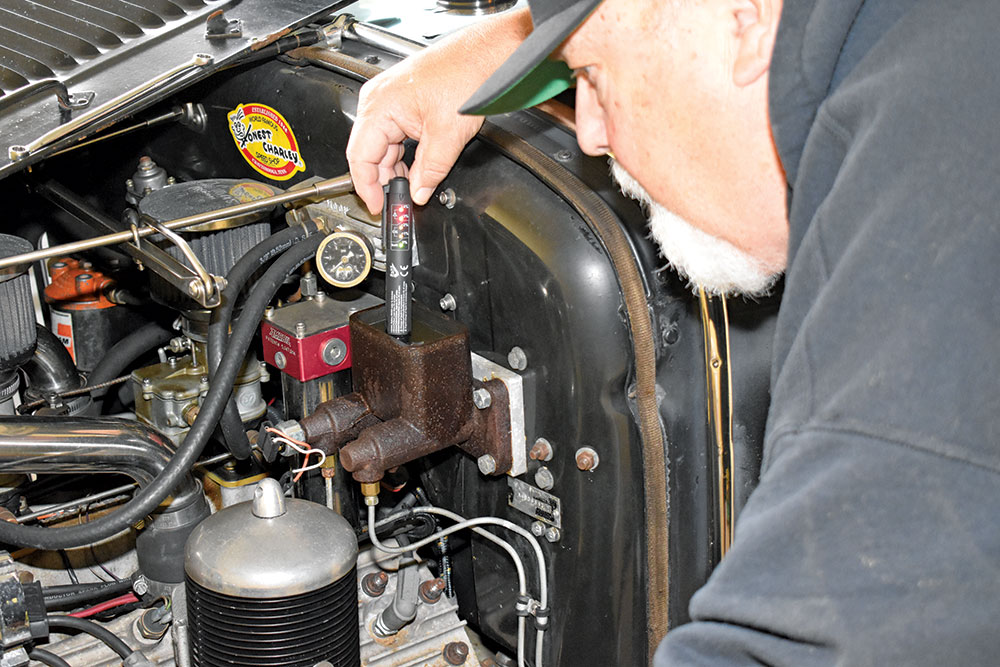
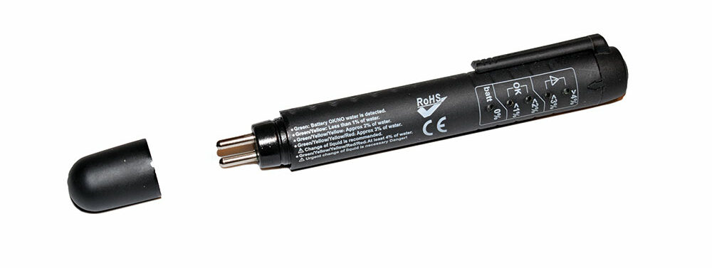
There are a variety of ways for moisture to enter a brake system. Day-to-day condensation from humidity can find its way into the system (even if your car isn’t being driven). Moisture can seep through pores in flexible brake lines, caliper/wheel cylinder seals, and past the filler cap gasket. Determining the water content in brake fluid is simple enough; brake fluid testers cost as little as $10 and are quick and easy to use. In any case, for the best performance and to increase the life of the system’s components, you should change your brake fluid every two years.
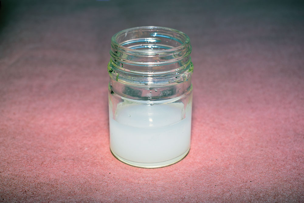
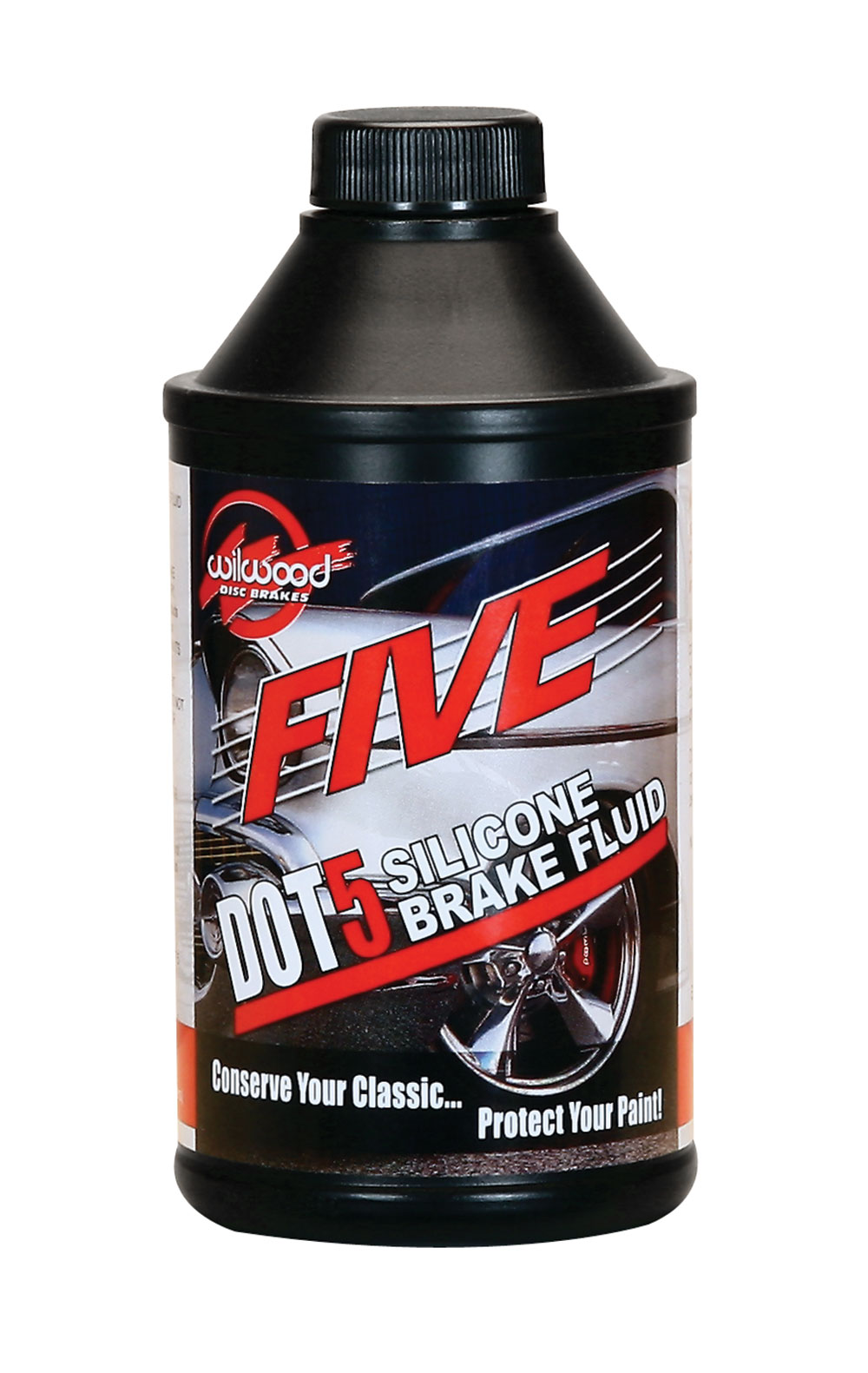
Another brake fluid option is silicone DOT 5 brake fluid. Since silicone fluid does not absorb moisture, it must be changed more often than glycol-based fluids as corrosion can be more of a factor with water accumulating in the system (the boiling point of this fluid can also be lowered dramatically). And while DOT 3, 4, and 5.1 glycol-based fluids are compatible with each other, they absolutely cannot be mixed with silicone DOT 5 brake fluid. The result of mixing glycol and silicone-based is a gel-like goo in the system with potentially disastrous results.

If there is an advantage to silicone brake fluid, it’s that it will not harm painted surfaces like glycol-based fluids will. However, Wilwood does not recommend using DOT 5 brake fluid in any racing applications as beads of water can collect in the calipers, then under heavy braking temperatures can become high enough to boil any moisture that has accumulated, causing vapor lock and system failure. Additionally, they caution that DOT 5 brake fluid is highly compressible due to aeration and foaming under normal braking conditions, providing a spongy brake feel.
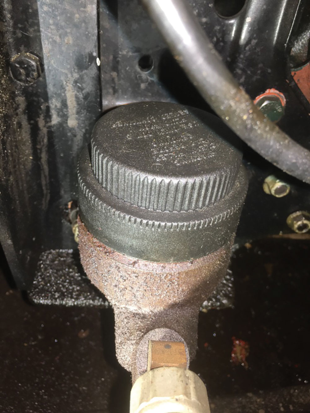
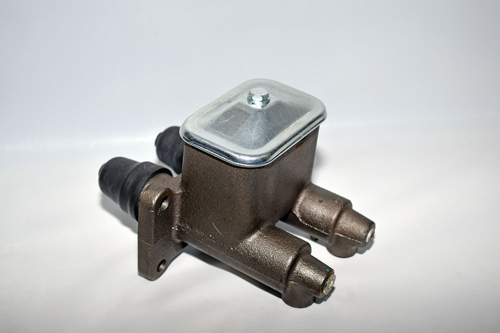
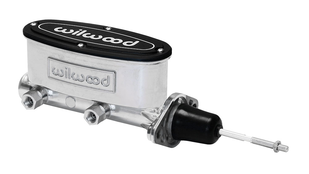
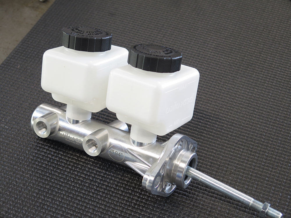
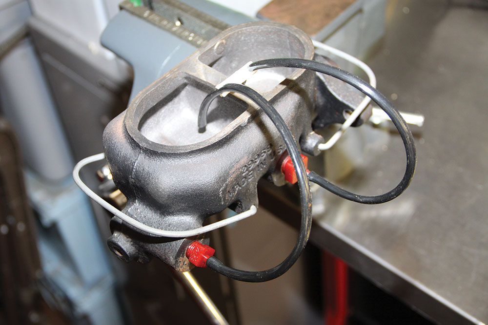
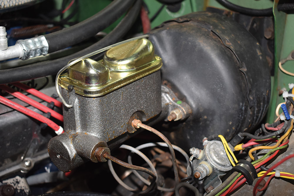
One of the most common mistakes when selecting brake components is choosing the wrong master cylinder. There are two types of master cylinders: single reservoir, single outlet master cylinders (like the Mustang fruit jar found on many hot rods built in the ’70s), and dual reservoir, dual-outlet master cylinders that split the front and rear hydraulic systems. The advantage to dual master cylinders is that if a leak causes a loss of hydraulic pressure in one half of the system, the other half still operates—and half of a car’s brakes are better than none.
Read More: Brake System Rehab: 1972 Ford F-100
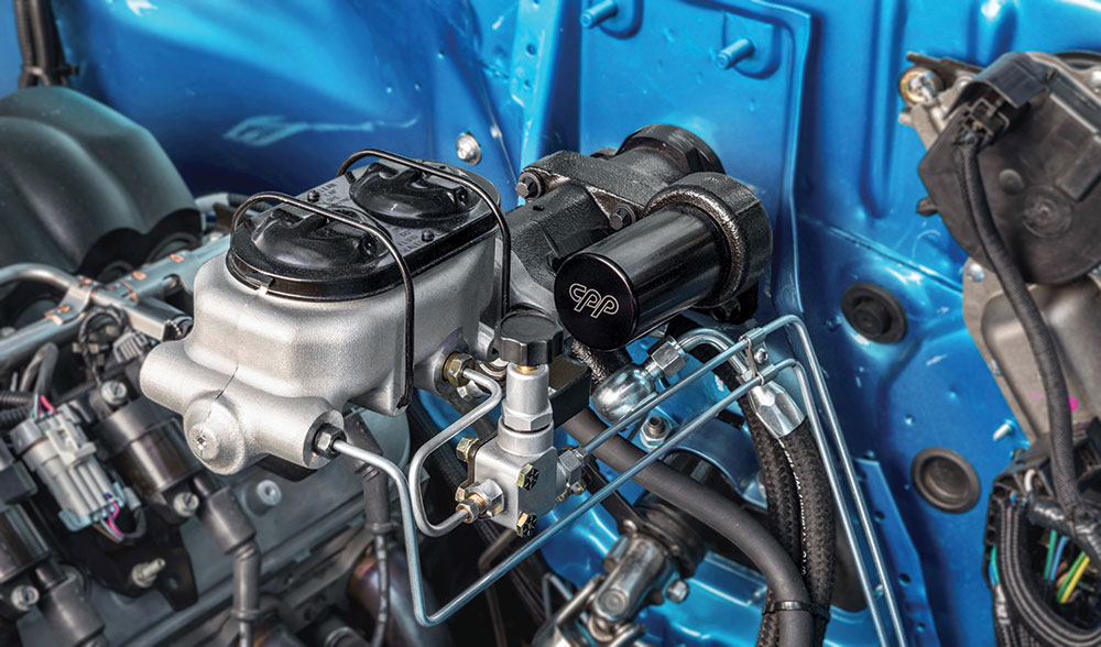
While master cylinders pretty much look the same, Classic Performance Products cautions that manual brake applications must use a deep bore master cylinder. That will allow the pushrod to extend around 1-1/2 inches into the master cylinder, preventing it from being able to fall out of the master cylinder. A shallow bore master cylinder will allow the power booster push rod to fit about 1/4 inch into the master cylinder. (Classic Performance Products has a bore adapter that will convert a standard GM deep bore into a shallow bore.)
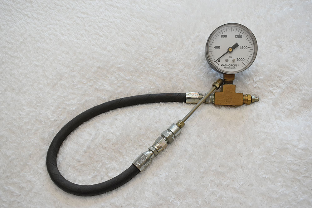
When selecting a master cylinder, Wilwood advises picking one that generates enough pressure to stop the car comfortably. (That means if you have to use both feet on the brake pedal to hold a car with an automatic transmission at a stoplight, you’ve got the wrong master cylinder.) Typically, OEM manual brake systems can produce hydraulic pressure in the 900- to 1,000-psi range, while power brakes may produce upwards of 1,400 psi.

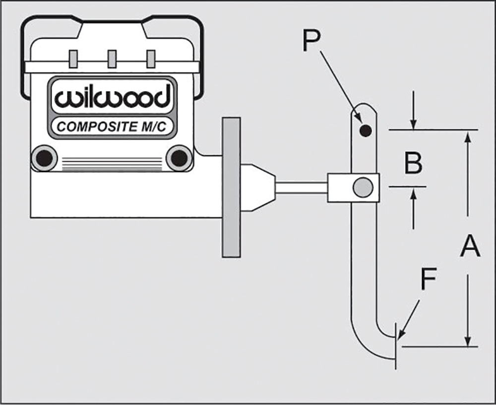
One of the factors that must be considered when choosing a master cylinder is the brake pedal ratio. Wilwood suggests at least a 5:1 ratio for cars in the 2,500 range and 6:1 for heavier cars. In operation, applying 100 pounds of pressure to a brake pedal with a 5:1 ratio would result in applying 500 pounds of pressure to the master cylinder. Increasing that ratio to 6:1 would result in 600 pounds of pressure applied to the master cylinder.
To determine the pressure a master cylinder will produce begins by figuring the area of the master cylinder’s bore by using the following formula: Area equal radius squared (multiplied by itself) multiplied by Pi (3.14). As an example, for a 1-inch bore master cylinder, the radius is half of that (0.50). Multiplying 0.50×0.50=0.250, multiply that by 3.14, and the result is the area of a 1-inch bore master cylinder, which is 0.785 inch.
By comparison, the area of a 15/16-inch master cylinder is determined by making the fraction into a decimal by dividing the top number by the bottom number: 15÷16=a diameter of .9375 divides that by 2 and the radius is 0.4688 inch. Square the radius (.4688x.4688) = 0.2198, multiply that by 3.14, and the area of a 15/16-inch master cylinder is .6902 inches.
Now if that hasn’t made your head hurt, here’s the cool part. To figure hydraulic pressure in a brake system multiply the pressure applied by the pedal ratio divided by the area of the master cylinder. As examples:
100 pounds applied to a 5.5:1 brake pedal with a 1-inch master cylinder: 100×5.5=550÷0.785=700.6 psi.
100 pounds applied to a 5.5:1 brake pedal with a 15/16-inch master cylinder: 100×5.5=550÷0.690=797.1 psi.
Now increase the pedal ratio to 6:1: 100 pounds x 6 = 600 ÷ 0.690 = 869.6 psi.
Of course, if you push on the pedal harder the amount of pressure produced in the system is increased: 125 pounds applied to the pedal results in 1087 psi, 150 pounds applied produces 1304 psi. While using a properly sized master cylinder will often make a brake booster unnecessary, boosters do reduce pedal pressure, particularly with heavier cars 3,000 pounds and up and can solve the problem when excessive pedal pressure is required for a safe stop.
Read More: Making A Canyon Carving C10: Big Brake Kit & Suspension Upgrades
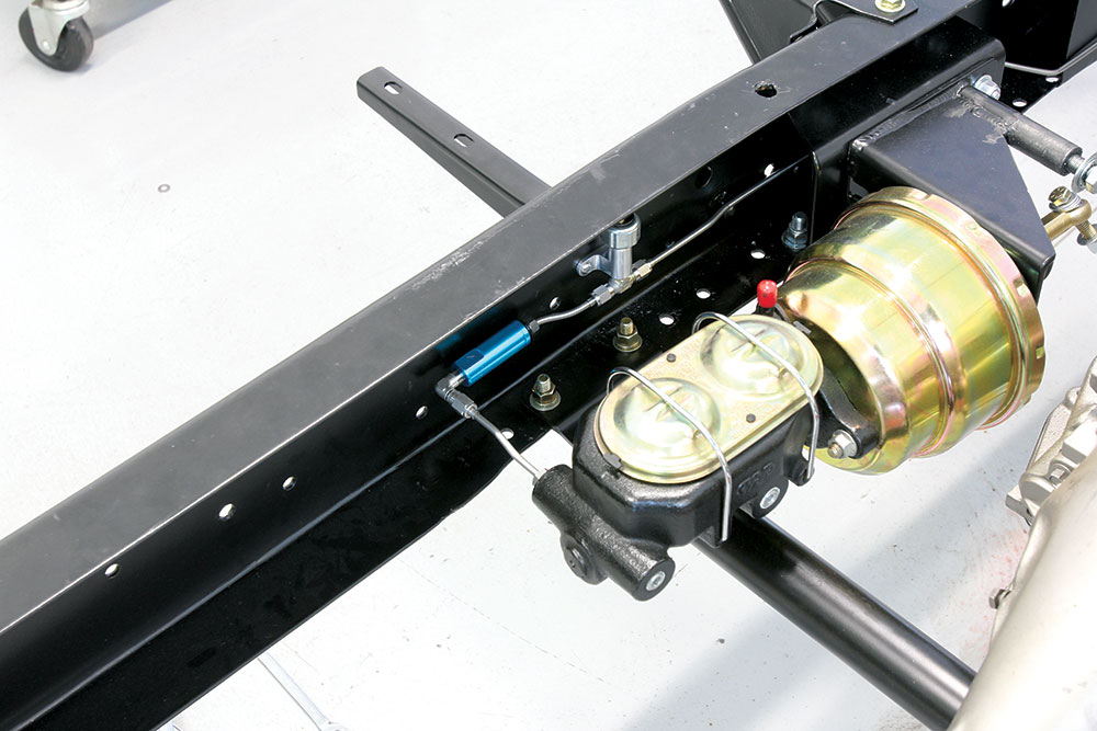
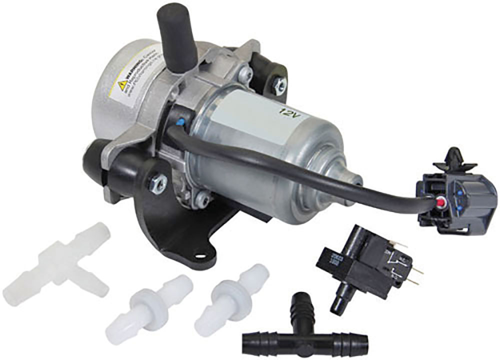
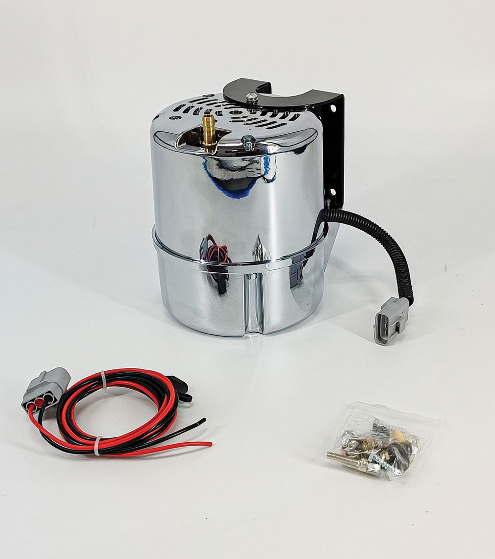
The most common type of brake booster is the vacuum style. Basically, there is a canister divided into two chambers by a diaphragm. On one side of the diaphragm are the brake pedal and a vent to atmospheric pressure; on the other side is a pushrod to the master cylinder and a hose leading to the intake manifold. When the brake pedal is depressed, atmospheric pressure is allowed to act on the brake pedal side of the diaphragm while vacuum draws air out of the master cylinder. The higher pressure on the brake pedal side simply helps apply more mechanical pressure to the master cylinder.
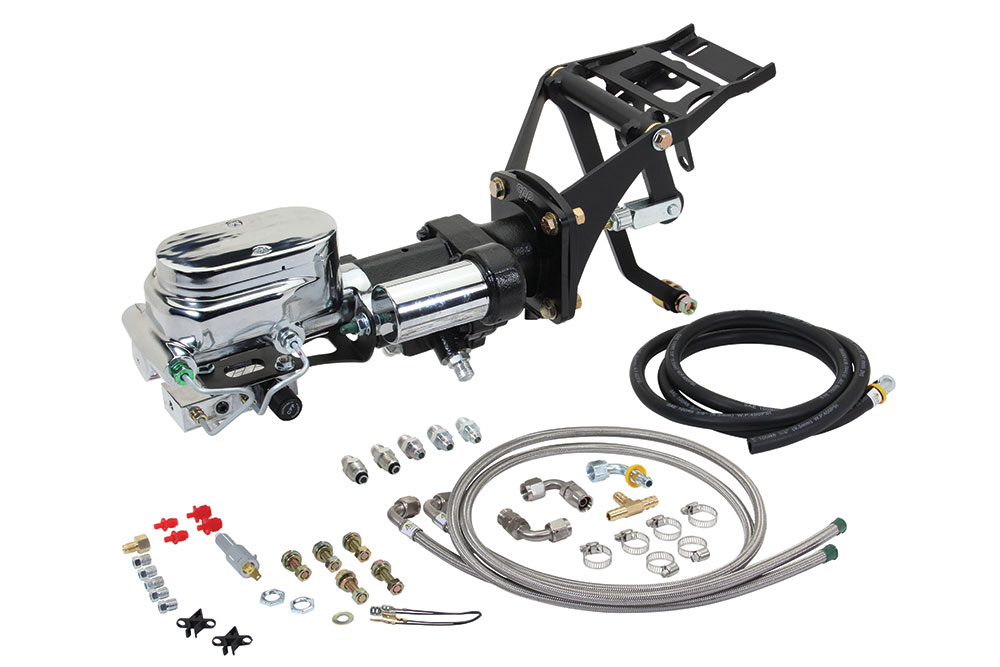
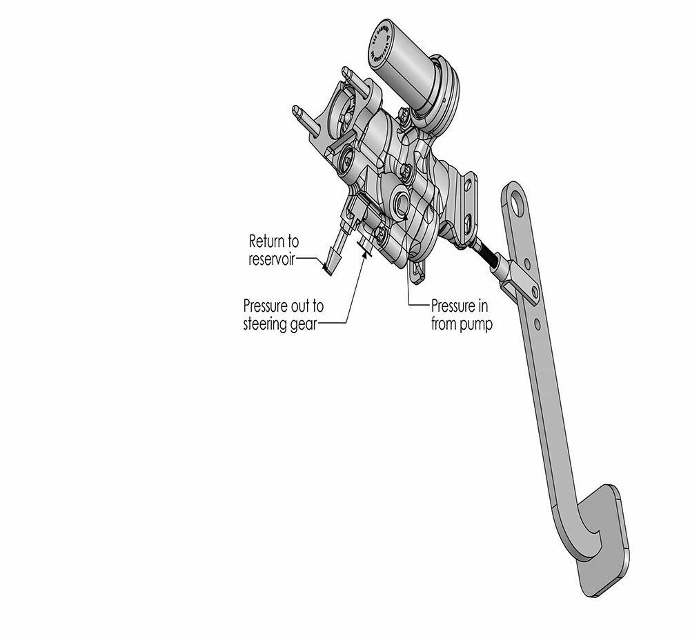
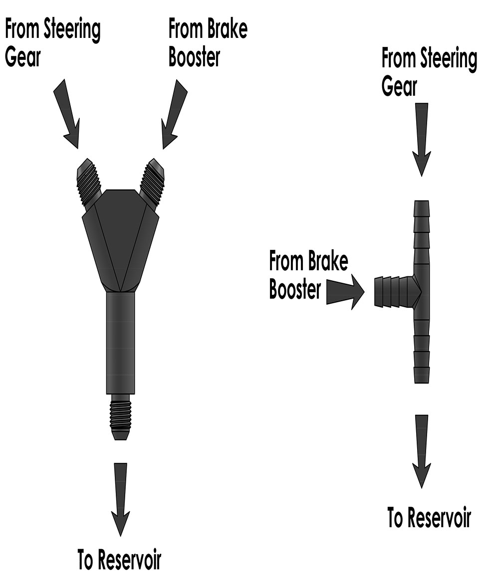
Another option are hydraulic boosters that tap into the power pump. In operation fluid flows from the power steering pump through the brake booster then onto the steering box. The steering box and the brake booster both have return lines, and to accommodate them the pumps used in these applications normally have two return fittings. When the brakes aren’t in use, fluid flows through the booster to the steering box. But when the brake pedal is depressed, pressurized fluid flows through a spool valve into a chamber in the booster where the fluid applies pressure to a piston, which pushes on the master cylinder providing the power assist. Typically, these systems have an accumulator that stores enough pressurized fluid for at least one assisted application of the brakes if the engine quits.
Choose the proper brake components that are best suited to your car and how it will be used and you’re well on the way to avoiding any brake blunders. Next time we’ll get into hooking all those cool parts together. MR
Sources
Classic Performance Products
(866) 882-6882
classicperform.com
Granatelli Motorsports
(805) 486-6644
granatellimotorsports.com
Speedway Motors
(800) 979-0122
speedwaymotors.com
Wilwood Engineering
(805) 388-1188
wilwood.com