

A Simple Overview of Rear Suspension Design From Leaf Springs to IRS
By Jeff Smith – Photography by Jeff Smith and the Manufacturers
When it comes to bad actor cars, most gearheads are all about making power and going quicker and faster. That places major emphasis on horsepower and torque but this also leads to the more challenging question of how to manage all that power and convert it into traction. This story will outline a basic understanding of the various rear suspension designs. Many enthusiasts gloss over these systems or merely follow whichever system seems to be currently popular.
As a true enthusiast, it’s important to understand how each of these systems function, what makes them different, and which one offers the best approach based on the performance goal. An optimal drag race rear suspension would be a crippling disadvantage trying to find bite coming off an autocross turn or on a road course.
We will look at the popular rear suspension designs with a simple overview of each. Because we must cram all these systems into a single story, this means we are forced to leave out a mountain of details. Think of this story as a smorgasbord or an ice cream taste test where you can quickly sample all the different flavors and then decide which offers the best one that suits your particular taste. You can then launch into a more detailed search into the system that best meets your goals.
Leaf Springs
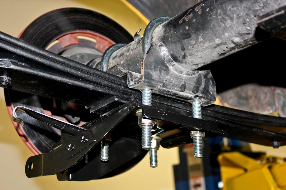
We’ll start with the simplest rear suspension that literally can be traced back to the 1700s when French carriage makers employed a flexible metal plate to cushion the ride that eventually evolved into the leaf spring. The modern automotive leaf spring is most often a multi-leaf configuration, but monoleaf springs are used, as with the ’67 Camaro.
The modern leaf spring combines multiple tasks into one component. The spring locates the rear axle housing in the vehicle, supports the weight of the rear half of the vehicle, while also providing suspension freedom of movement.
When power is applied to a leaf spring, the pinion gear attempts to climb the ring gear but is resisted because the rear axle tubes are attached to the spring. Torque is applied through the leading half of the main leaf spring, which can deflect it just behind where the spring eye attaches to the body. With hard acceleration from a standing start, this force can cause the main leaf to deform into an S shape. If enough torque is applied, the S shape eventually binds the spring, which violently forces itself back to its original shape, causing the rear tire to leave the road surface. This creates what is called wheelhop.

There are several time-honored solutions to prevent wheelhop. Chrysler long ago moved the mounting position of the rear axle on the spring to shorten the distance from the axle tube to the front spring eye. This effectively strengthens the leading side of the spring, which minimizes spring wrap and wheelhop. These cars are often also equipped with a pinion snubber that limits pinion travel and improves traction.
Read More: Giving a Well-Worn, 42-year-old Chassis a New Lease on Life
The classic traction bar solution for GM leaf spring cars was to bolt a rectangular steel tube to the leaf spring mount fitted with a rubber snubber designed to contact the forward part of the spring. The traction bar prevents spring wrapup but also binds the spring. This works adequately for straight line drag racing but creates essentially an infinite spring rate, which causes massive oversteer when power is applied when exiting a corner.
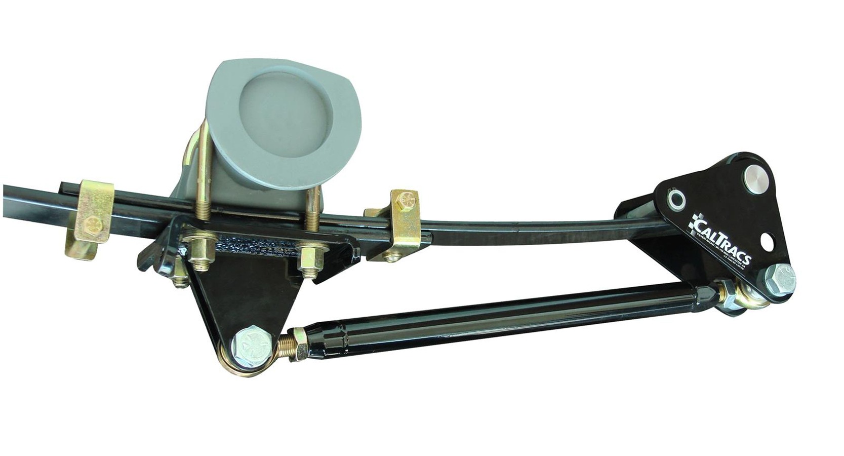
A far better solution is the CalTracs bar and its many variants. This design mounts a round tube link directly under the rear axle spring pad that extends forward to a mount directly below the front spring eye. This front mount includes three different mounting locations for the leading end of the bar. This device minimizes spring wrap while not binding so the spring functions normally when load is applied.
Instant Center
This is a good place to bring up the concept of the rear suspension’s instant center (IC). This is an imaginary point in space that functions as the location of the force driving the vehicle forward during acceleration. This is a complex arrangement that we will mention several times throughout this story, but it is beyond the scope of this story to delve into its many details. We suggest you read other technical pieces to become more familiar with how the IC affects traction during acceleration.
In a typical leaf spring application, the IC is often found at the front spring eye, although not in all cases. When a traction device like the CalTracs bar is applied, the torque is applied through the lower bar so that the IC is formed by extending imaginary lines forward that trace the position of the main leaf spring and the CalTracs lower bar. The IC can be changed by relocating the front mounting position of the lower bar. This offers tuning options that affect traction.
Coil Springs
Coil springs were a natural evolution of leaf springs, offering support for vehicle weight in a smaller, lighter package compared to bulky leaf springs. While smaller and lighter, coil springs do not locate the rear axle housing like leaf springs. This task must be performed by separate locating devices called trailing arms. The orientation of these trailing arms leads us into a variety of different rear suspension configurations.
Ladder Bars
From a simplistic viewpoint, the next rear suspension configuration is the simple ladder bar. This design has been popularized in drag racing rear suspension using a pair of triangle-shaped bars mounted between the rear axle and a frame crossmember. The advantage of a ladder bar suspension is the forward locating point in the rear suspension’s IC. This can be repositioned vertically to adjust the application of torque during the launch. However, a major disadvantage is that the IC point cannot be adjusted forward or backward in the car without physically changing the length of the ladder bar.
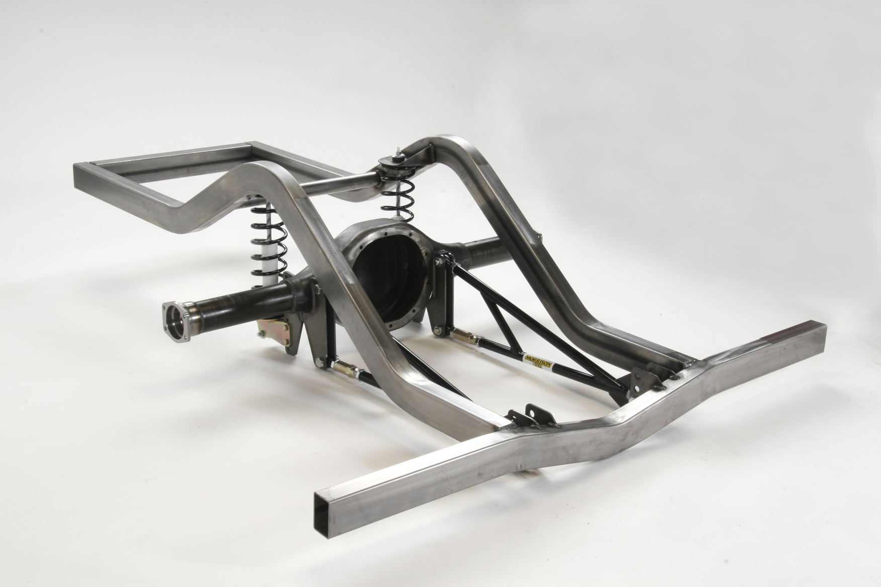
A pair of ladder bars creates two sets of parallel bars that form a basic rectangle around the rear suspension. Unfortunately, this configuration offers no lateral (side to side) control over rear axle movement. This means ladder bars (and other systems we’ll address next) require some type of separate control mechanism that will minimize lateral movement.
More Chevy Suspension: Dragstrip Shock Tuning
There are multiple solutions to solve this issue but the simplest is a track bar that laterally connects the front of one lower arm with the rear link of the opposite lower bar. This forms a right triangle in between the two parallel lower arms. This triangle prevents unwanted lateral movement by virtue of the right-angle connections. Track bars are fine for straight ahead drag cars but place extremely high loads on the spherical joints during cornering so these track bars should not be used in street or high-force cornering applications like road racing or autocross. A better solution is either a Panhard bar or Watt’s linkage that will be detailed later.
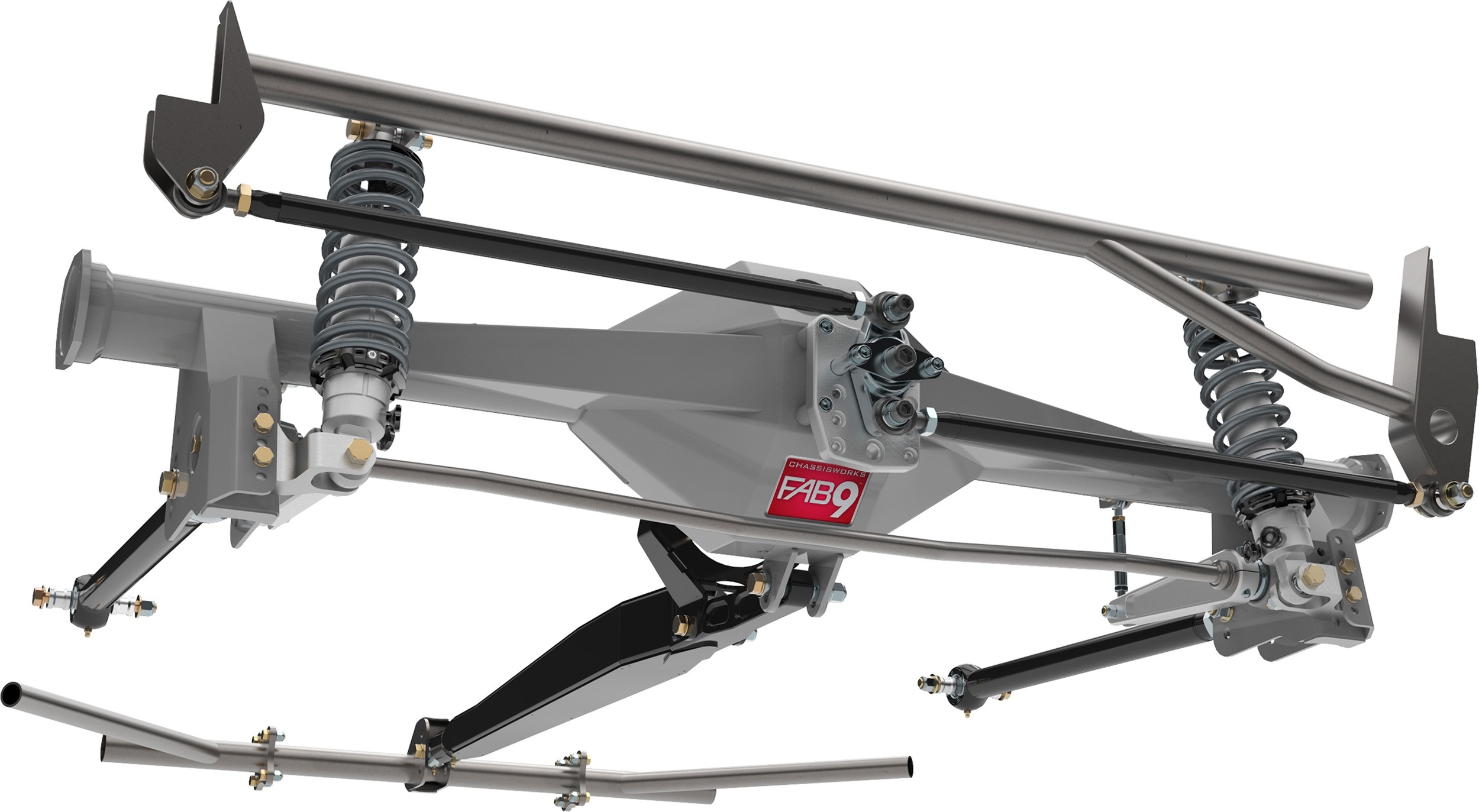
Parallel Four-Link
The parallel four-link rear suspension is generally considered as an upgrade to the simple ladder bar. The parallel four-link uses lower control arms to position the rear axle in the car and are connected to the lower portion of the rear axle. The upper arms are connected over the top of the rear axle and also connect to the frame with shorter tubes. The shorter tubes are used to help in packaging the system under the existing floor. The upper arms are used to maintain the pinion position during acceleration and deceleration.
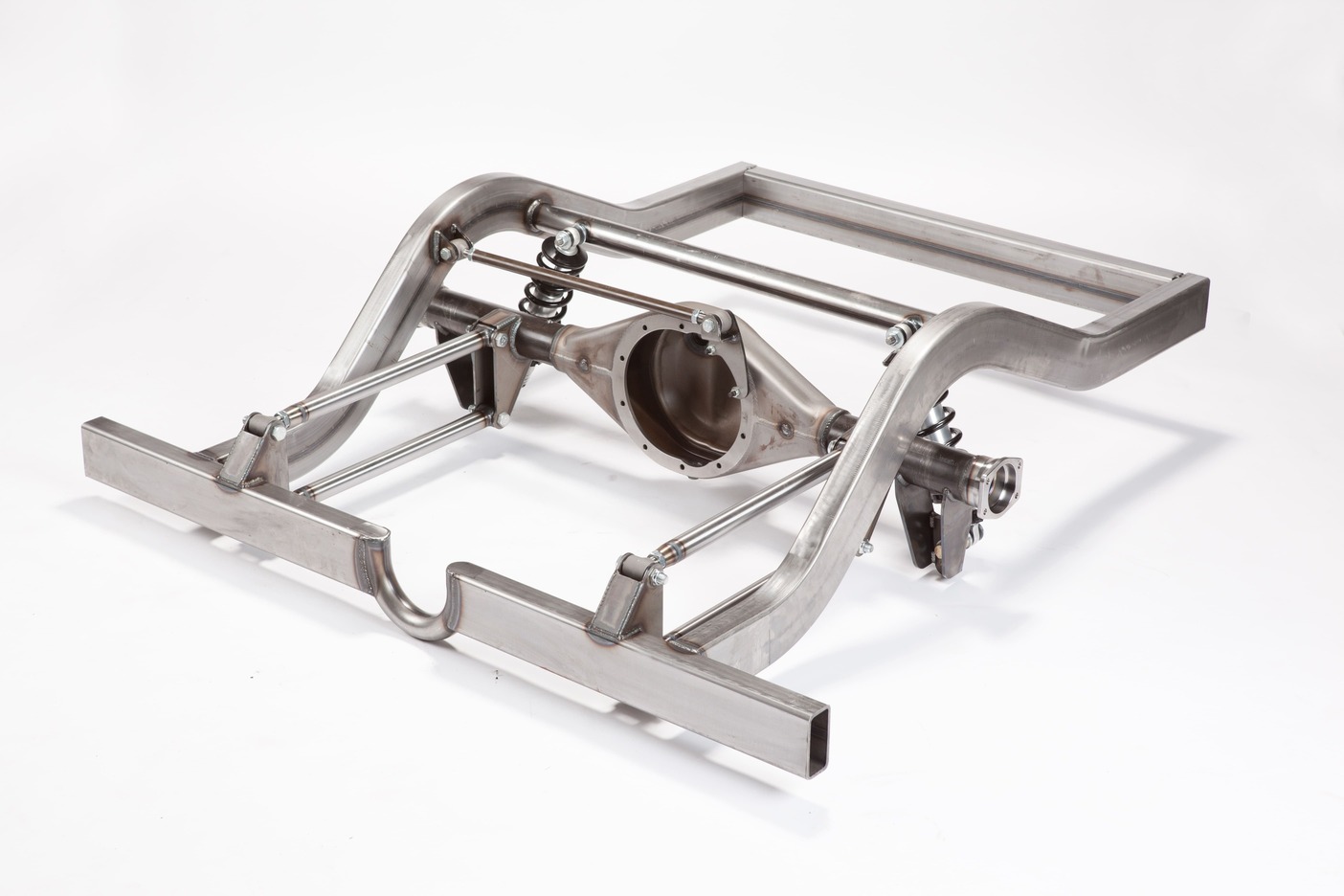
It’s also important to understand the dynamics of what happens to these arms under acceleration. As torque is applied to the rear axle, the pinion tries to climb the ring gear, this imparts tension on the upper control arms while simultaneously pushing forward on the lower trailing arms. The motive force to drive the car forward is through the lower trailing arms.
As mentioned, this four-link orientation is similar to the ladder bar in that it also requires some way to laterally locate the rear axle. Various solutions have been offered to provide this control, including the Panhard bar and the Watt’s linkage.
A slight variation of the parallel four-link is a popular OE application called the non-parallel four-link. This system uses a pair of parallel lower trailing arms but splays the upper arms outward from the rear axle to create a triangle. This triangle laterally locates the rear axle and eliminates the need for a track bar, Panhard, or Watt’s linkage. You can find an OE example of this suspension in ’64-72 Chevelles and many subsequent GM cars.
One difficulty or limitation of the non-parallel four-link system is that if the car is dramatically lowered or raised, the short upper lengths can easily go into bind, which wedges the rear suspension in place. In severe cases this can cause the upper factory trailing arms to buckle and fail. However, a properly designed aftermarket non-parallel four-link using spherical joints instead of bushings offers multiple advantages while maintaining a very simple configuration.
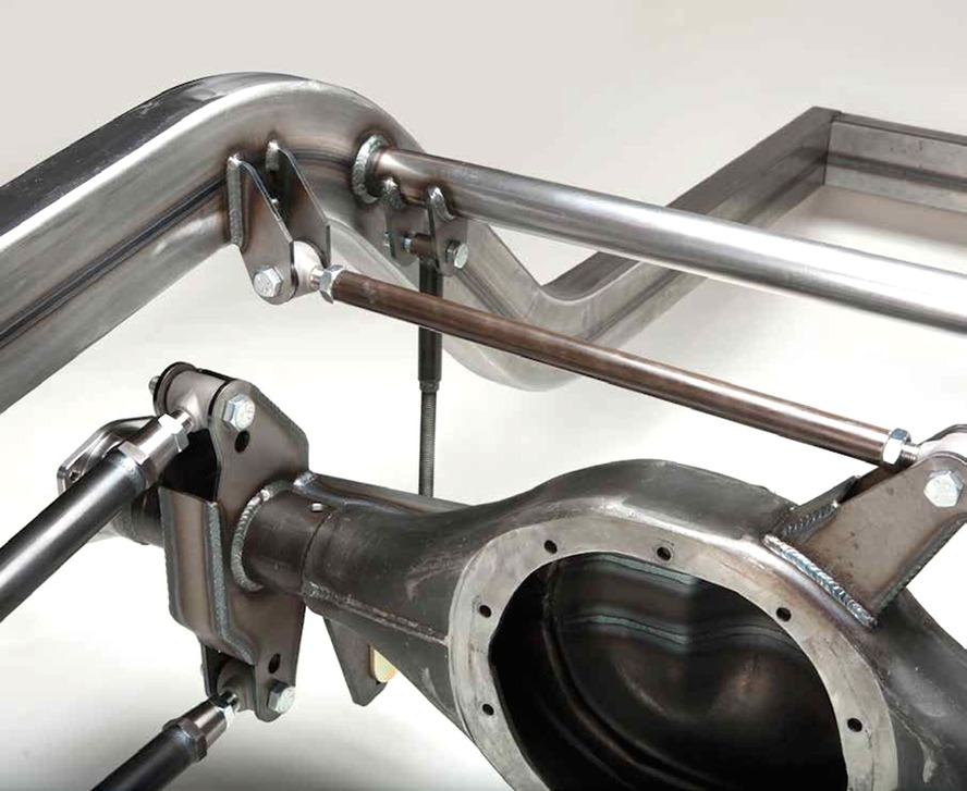
Three-Link
One variation of the parallel four-link is the three-link system that eliminates one of the upper control arms, leaving a single trailing arm usually either in the center or on one side of the axle housing. An early example of this is the X-frame ’58-64 B-body Chevrolet. In a racing situation, three-link rear suspensions are favored in some high-powered dirt track applications because this arrangement allows the rear axle to articulate under a huge range of suspension travel. Again, this style of suspension demands some type of lateral control mechanism, such as a Panhard bar or Watt’s linkage.
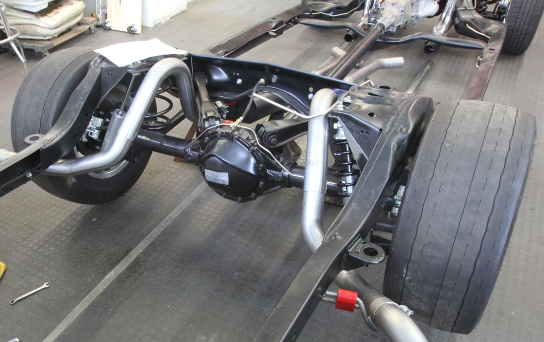
Torque Arm
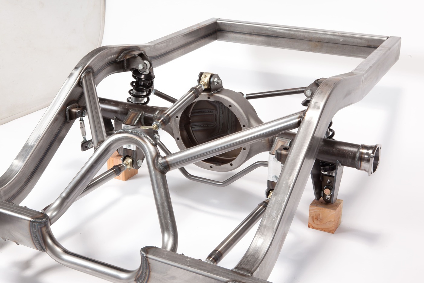
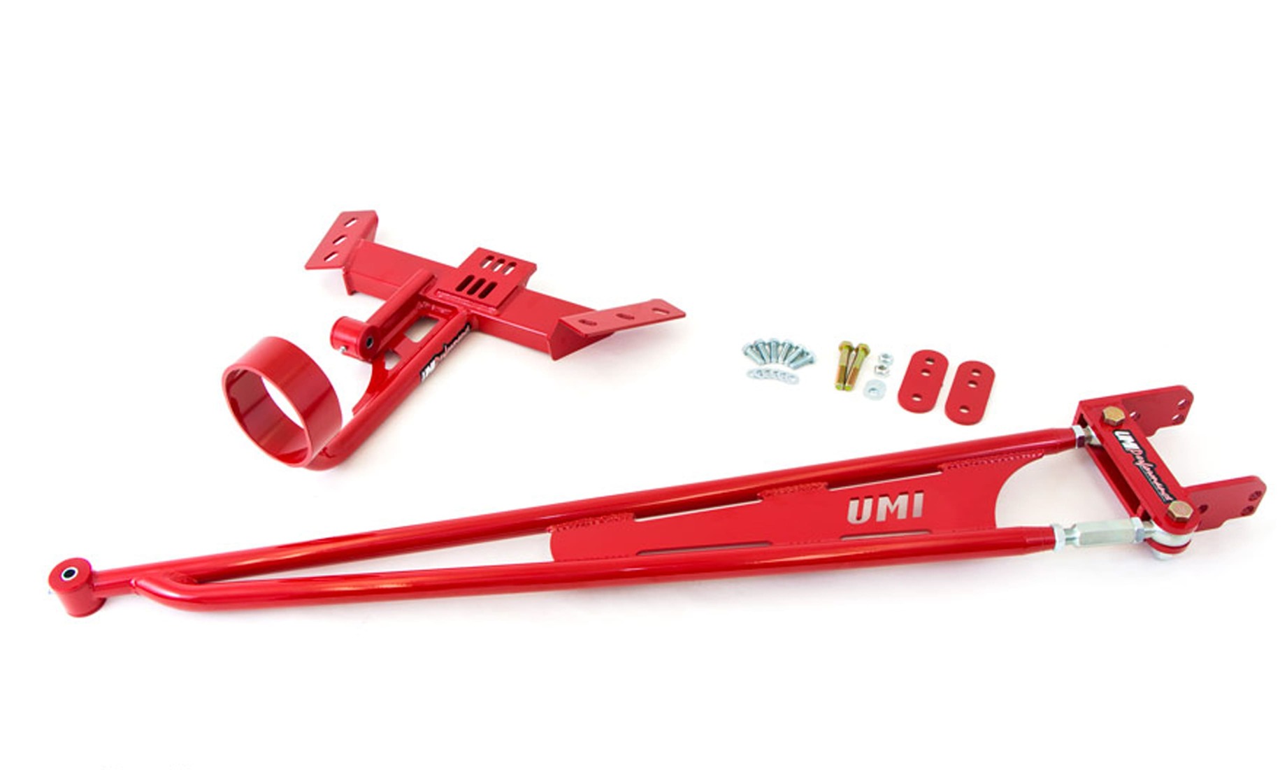
This is a late-model variation of the three-link system first popularized in GM cars with the Buick GNX and also in the third- and fourth-generation F-body Camaro/Firebird. The torque arm is similar to a four-link using twin parallel lower trailing arms connecting the rear axle to the frame of the vehicle. But that’s where the similarity ends. In production cars like the Camaro, the upper trailing arms are replaced with a long, stamped arm that connects the pinion of the rear axle to a mid-mounted crossmember usually located near the tailshaft of the transmission.

This type of suspension is useful when faced with space limitations where there is minimal room for both upper control arms and a full exhaust system. Aftermarket torque arms offer the advantage of changing the mounting position for the torque arm, but this is usually limited to vertical options. The location for the IC for these suspensions is found by extending an imaginary line from the rear lower control arm mounting point through its front mounting point to where it intersects with a perpendicular line that crosses the front mount location of the torque arm. This can be altered by changing the lower control arm rear locating point.
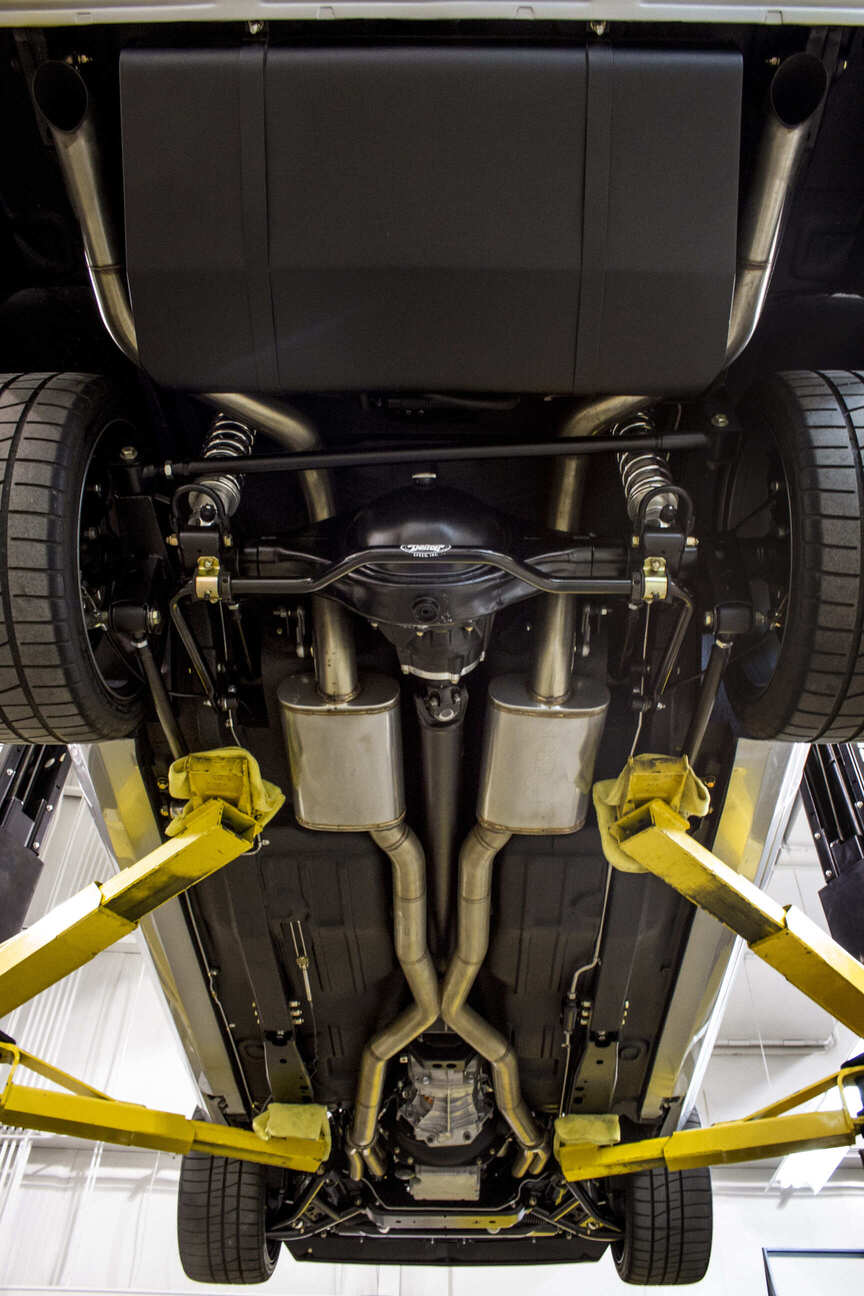
Panhard Bar and Watt’s Linkage
Earlier we promised to explain the use of both axle locating devices. When a parallel four-link suspension is employed for a street-driven vehicle, substantial components are needed to locate lateral or sideways movement of the solid rear axle assembly. The simpler of these two devices is the Panhard bar that uses one location point mounted on the rear axle and the other positioned on the opposite side of the rear axle bolted to the frame.
As the rear axle moves up and down in suspension travel, the Panhard bar will produce lateral movement in the shape of an arc. It’s important that the Panhard bar be as long as possible in order to scribe the widest arc during rear suspension travel. This will minimize this lateral movement of the housing under the frame during rear suspension travel.
A Watt’s linkage accomplishes the same task of limiting rear axle lateral movement but employs a slightly more complex arrangement to do so. The Watt’s linkage uses a pair of parallel rods with one end connected to the frame and connected to a central pivot point often located behind the differential. The system should be designed so that the two links are parallel to the ground with the vehicle at ride height. This allows rear suspension travel with a minimum of lateral movement. The negative to this arrangement is its complexity and additional weight, much of which is added to the unsprung weight of the rear axle assembly.
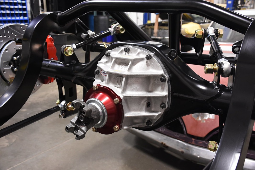
Independent Rear Suspension (IRS)
For years enthusiasts have argued the relative advantages of an independent rear suspension (IRS) compared to a solid rear axle assembly. Rather than add to this cacophony, we will merely address the basic function of an IRS. As with an independent front suspension, there are inherent advantages to allowing each rear tire to move independently of its partner. Early attempts at creating independent rear systems were called swing arm suspensions that pivoted only from the inboard mounted side of the system as with early VWs or early Corvairs. During high-speed cornering, major suspension movement created huge camber changes to the rear wheels and tires.
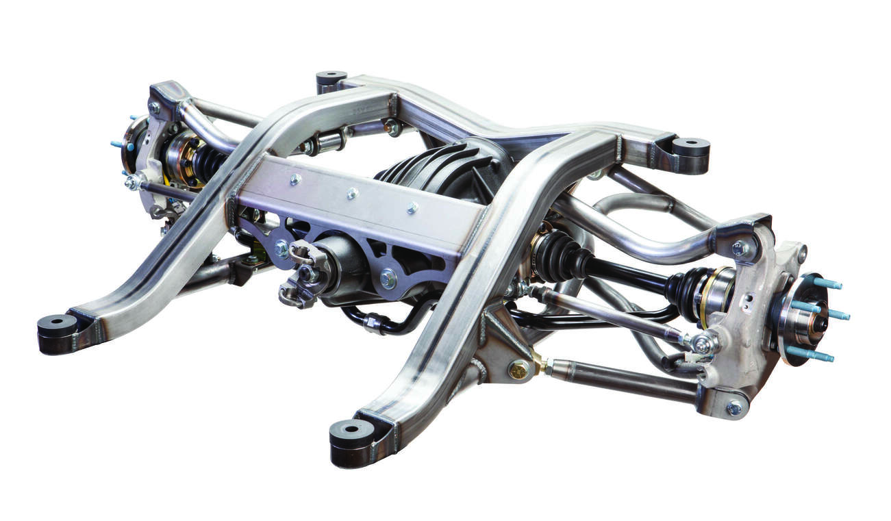
A true IRS allows the axle shafts to pivot at both the inner and outer points with spindles locating the outer hub with lateral control arms. The earliest Chevy IRS was first used in the ’63 Corvette and has been improved over the years into a highly refined system. Even the current-generation Camaro now enjoys an IRS. The major advantage to IRS is much more control over wheel motion, which is a shorthand description of the combination of changes to caster, camber, and toe for each rear tire as it travels through suspension motion. An optimally tuned IRS can create ideal wheel motion for improved handling. An example of this is the ability to easily set rear camber and toe angles that cannot be easily accomplished with a solid rear axle.
There are many more considerations to IRS advantages that go much further than this abbreviated look can allow. The only major disadvantage to converting a solid rear axle car over to IRS is the cost.
As performance cars become more sophisticated and torque and horsepower continues to increase at a phenomenal rate, this only increases the need for awareness as to the rear suspension needed to help manage all this newfound power.
Sources
Art Morrison Enterprises
(866) 808-4759
artmorrison.com
Chris Alston’s Chassisworks
(888) 388-0297
cachassisworks.com
Detroit Speed
(704) 662-3272
detroitspeed.com
Dobbertin Performance
(315) 683-0022
http://rick486.wixsite.com/dobbertinperformance
Heidts Hot Rod and Muscle Cars
(800) 841-8188
heidts.com
Roadster Shop
(847) 949-7637
roadstershop.com
Scott’s Hotrods ’N Customs
(800) 273-5159
scottshotrods.com
Schwartz Performance
(815) 770-0751
schwartzperformance.com
UMI Performance
(814) 343-6315
umiperformance.com