


Notes for Shock Setting in Drag Racing Application
By Jeff Smith – Photography by the Author
At some point trips to the dragstrip became more about improving the car’s 60-foot and overall elapsed time and less about going heads-up against that guy in the other lane. You also begin to notice that the fast cars all leave the starting line hard yet straight while many squirrelly street cars perform these weird gyrations with the car lifting the left front while the rear squats hard over the tires. Somewhere along this timeline you decide your car’s 60-foot times are too slow and you’re ready to make some changes.
Drag racing has always been about making more power than the other guy, but it’s also about the art of converting that power into traction to go quicker. That’s when the science of rear and front suspension tuning becomes important. This story will focus on a common problem that is often overlooked once the car is quicker—we’ll draw that line at roughly the low 12s to mid 11-second bracket. Once a car reaches this threshold, applying careful suspension tuning with the right parts can make a big difference.
A recent tech discussion with Viking Shocks co-owner Chris King revealed that a common problem is rear suspension loss of control due to insufficient shock travel. This is most commonly seen in coilover applications but also occurs in stock suspension applications. The scenario plays out something like this: You’ve just added a looser converter or plumbed a mild nitrous kit that now hits the tires so hard on the starting line that the body squats over the rear suspension and the tires spin. This often creates a situation where body movement fully compresses the rear shocks, creating a solid rear wheel rate that translates into spinning rear tires. We’ll first run through some simple measurement techniques that should alert you to the possibility that a shock length and/or a rear spring rate change may be needed.
The first thing to do when looking at improving 60-foot times is to inspect and ensure all the suspension components are in good shape. If there are wiped out rubber control arm bushings, dead ball joints, leaking shock absorbers, or bent control arms, these issues must be addressed first. Insufficient rear shock travel can also prevent creating a decent baseline. Establishing a repeatable baseline from which to start tuning is an essential first step.
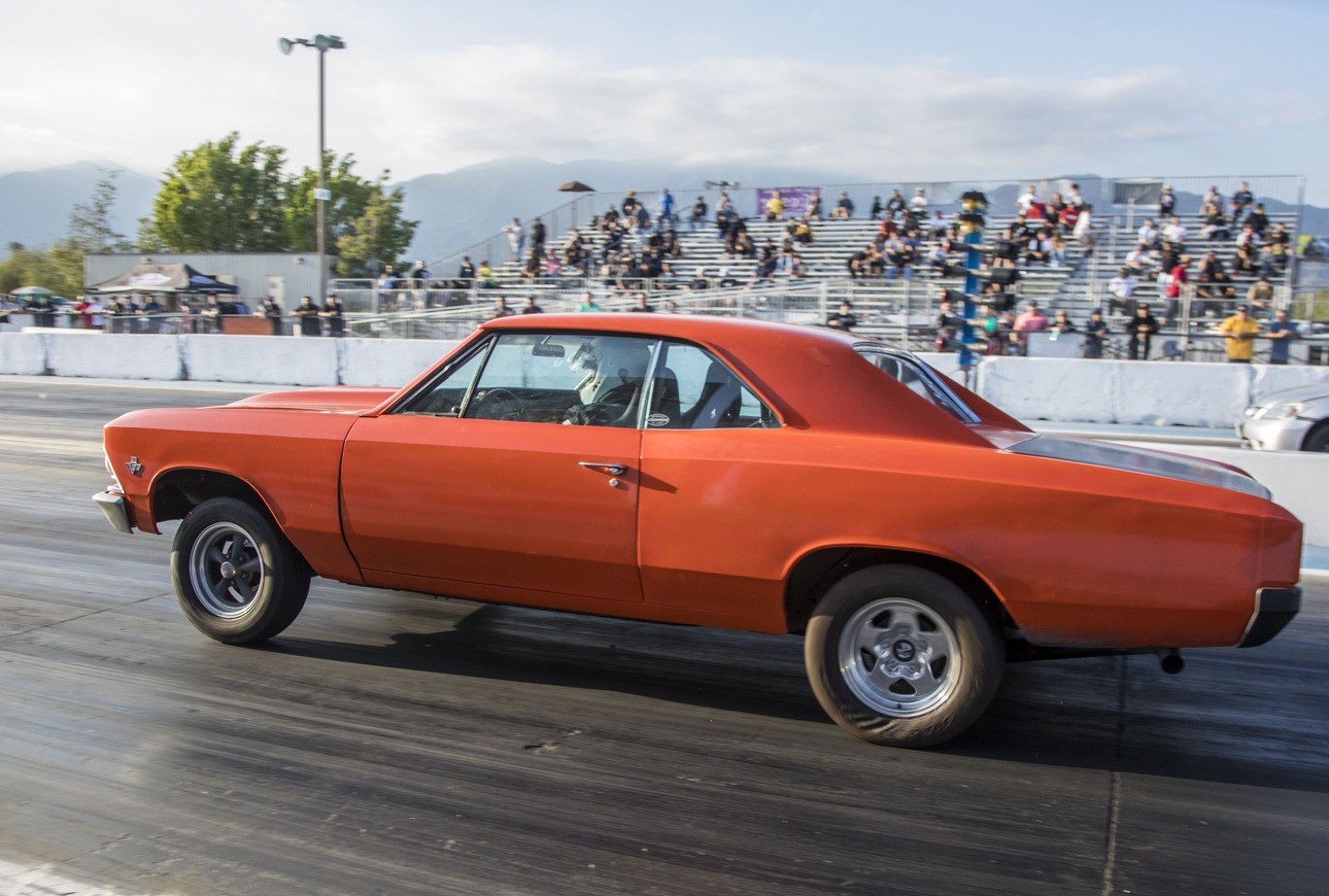
For this story, we will be using an early Chevelle rear suspension with factory separate shocks and coil springs, but this approach will work just as easily for a coilover conversion.
Before we get into the measurement phase, it’s best to record all this information with the exact configuration it will run on the starting line. This means the car should be set up with the usual amount of fuel in the tank, the equivalent driver weight in the seat, and with the normal tire pressure in the front and rear tires. This level of detail will produce much more accurate results.
Read More: The Chassis Refresh
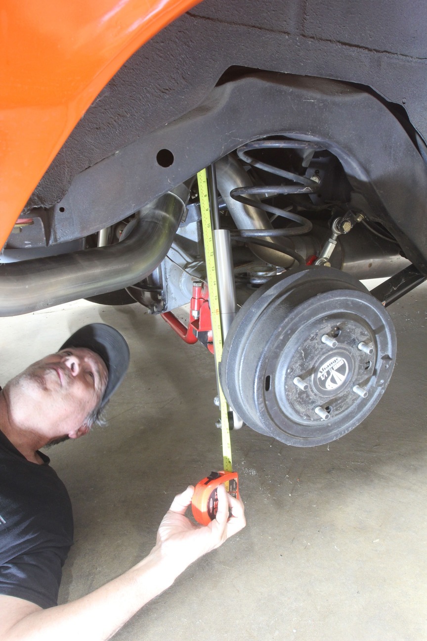
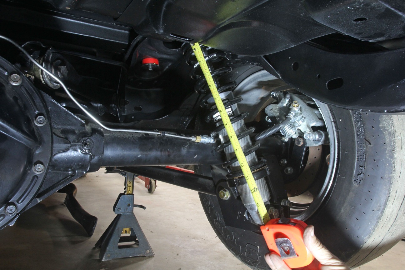
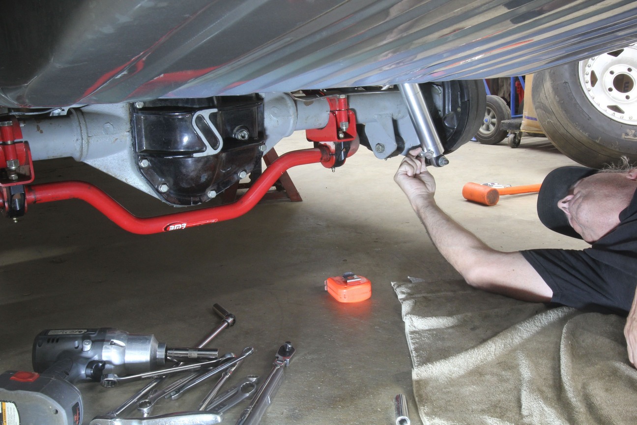
The first step is to establish rear ride height. In our case, we measured the distance from the axle centerline to the horizontal fender lip but you could also use the distance from the fender lip to the ground. Once this position is recorded for both sides, measure the length of both shocks at ride height and record that measurement.
Next, measure the length of the shaft extending from the top of the shock body to the upper mounting position. Also, with the car at ride height, measure the height of the compressed rear springs on both sides and then remove the spring and measure the free length of the spring. Finally, remove the shock and measure the shock length in both full extension and full compression and record all these numbers.
A reasonable initial setting should produce 20 to 25 percent of load on the spring at ride height. As an example, if our Chevelle weighs 3,400 pounds and we have 42 percent of the total weight supported by the rear springs, that would put the rear weight at 1,428 pounds with that split evenly at 714 pounds per side. In order to place the load on the springs at roughly 25 percent of its maximum we might start with a spring rate of roughly 175 pounds per inch.
You will get an idea of your relative spring rate by comparing the free height of the spring with how much the rear springs compress at ride height. If the rear springs compress barely 10 percent this indicates a stiff spring (assuming freedom of movement). If the spring compresses to 50 percent or more of its free length, then the spring rate is likely too soft. One advantage to coilover shock applications is that there are many more spring rates available and the rate is often marked on the spring.

One goal of this effort is to achieve roughly 25 percent of spring compression at ride height along with a minimum of 2.25 to 2.5 inches of shock movement in both compression and rebound (extension). This means having a minimum preferable overall travel of 5 inches.
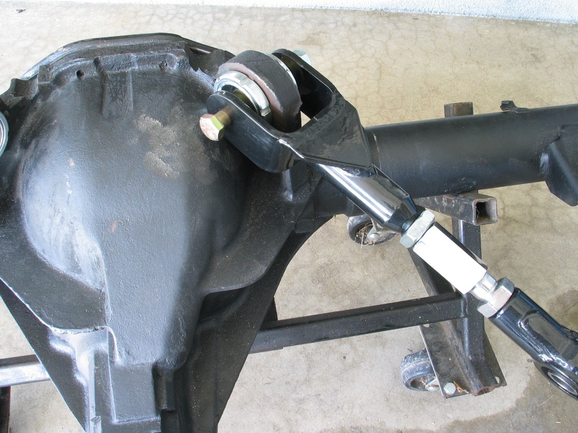
Before we get into the subject of the vehicle’s instant center, it’s important to touch on the possibility of suspension bind with a bad shock absorber. This emphasis on a free moving front and rear suspension includes stock-type rubber suspension bushings that, by design, do not allow free movement of the suspension. This is where converting to better rear suspension bushings can really help. On our Chevelle, we’ve converted to tubular upper and lower control arms using a combination of spherical bearings—aluminum and Delrin suspension bushings.
Check it out: Easy and Affordable Brake Upgrade for a ’70s Nova
Global West pioneered the use of combining lightweight aluminum suspension bushings with this Delrin material at the wear points. Other suspension companies have followed suit. For our Chevelle, Global combines a steel spherical bearing in the front of the lower control arm with a Delrin rear bushing in the rear to allow complete freedom of movement while positively locating the rear suspension. This advantage is further enhanced with spherical bearings in the upper control arm as well combined with an adjustable upper arm that offers the ability to easily set the pinion angle. There are several other suspension companies that also offer the combination of aluminum and Delrin bushings.
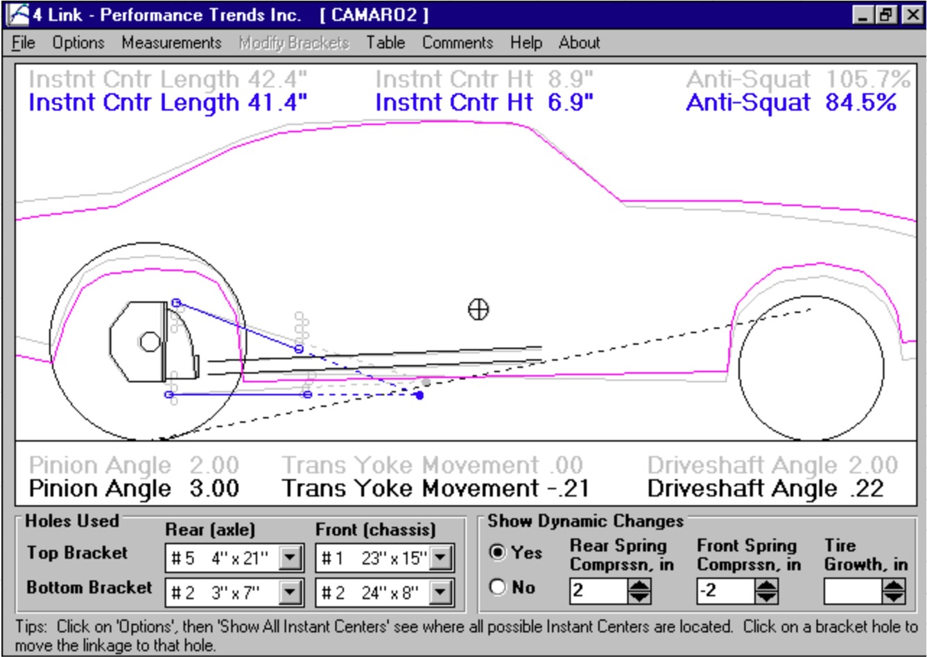
If you find it necessary to change the rear ride height in order to create the ideal rear spring position, keep in mind this will also affect the instant center (IC). The instant center is the theoretical intersection of the upper and lower control arms on a typical four-link rear suspension. On a ladder bar car, the IC is the front attachment point of the ladder bar to the chassis. On a leaf spring car, the IC is the leaf spring’s front mount position. It would take a separate tech story to explain positioning and tuning of the IC so we’ll leave it to the reader to do his own research on that topic.
The ideal position of the IC is to create a rear suspension that initially extends or pushes the rear axle downward to plant the tire. If the car squats (where the body pushes down over the rear tire), this effectively is lifting the rear tire off the track surface, which reduces traction. Ideally, we want the body at the rear to either be level or slightly lift on the launch.
From a simplistic standpoint, the greater the distance the IC is forward of the rear axle centerline, the greater the leverage applied to the rear suspension. So, if the body squats on acceleration, this generally indicates the IC is too far forward. Raising the rear ride height will tend to shorten the IC horizontal distance while lowering the ride height will do the exact opposite and lengthen the IC position. The vertical position of the IC is also important but, again, beyond this story to get into the specifics.
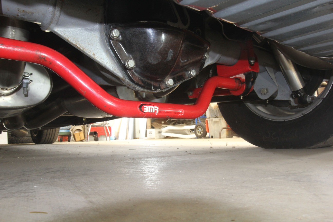
It’s also important to emphasize that the IC is not locked in a fixed position as the car accelerates. When the rear suspension moves on launch this changes the angle or pitch of both the upper and lower control arms. This will reposition the instant center and therefore affect how the car responds. In addition, under load it is not unusual for the axle to rotate (lifting the right rear tire as viewed from behind the car), which will compress the right (passenger) side shock by 1/2 inch or more. One way to maintain a relatively even axle position is to use a large, rear antiroll bar. These is an important addition for cars running 11s and quicker.
Once you have created a solid baseline position for the rear shocks and ride height, the next process is to begin tuning the shocks to optimize the launch. The best approach is to use double-adjustable shocks so that the compression and rebound settings can be optimized independently. Compression movement is when the shock is shortened while rebound is the opposite or extension of the shock.
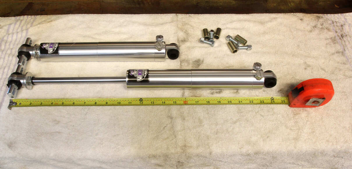
Our specific application ’66 Chevelle uses a Strange S60 rear axle housing with stock locations for the springs and shocks with tubular upper and lower control arms. If you discover, as we did that the stock length rear shocks were too short to allow for adequate suspension travel, we consulted with Viking and they recommended a ’66 B-body Buick shock that would bolt right up to our existing Chevelle mounting points yet offer a 1½-inch increase in suspension travel.
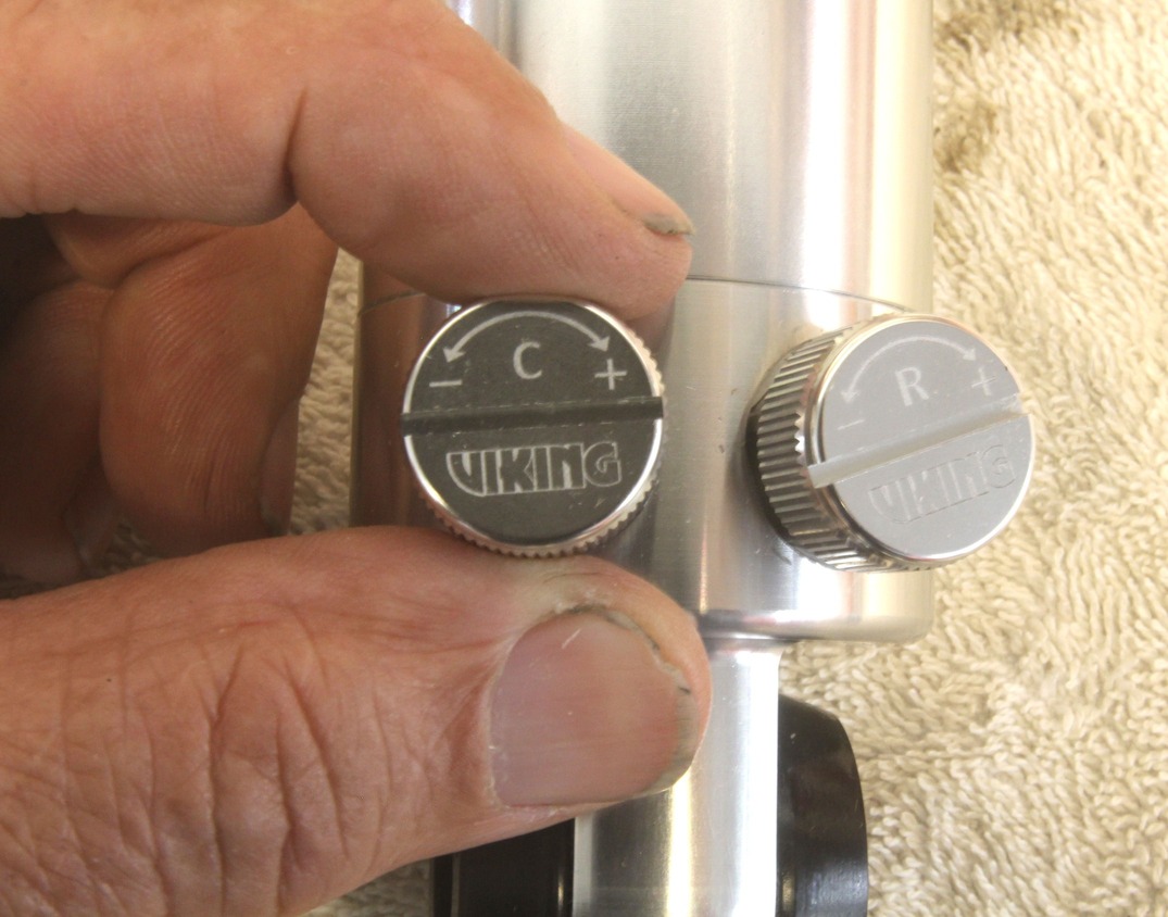
Assuming that the car extends the shock at the launch, extension valving is the adjustment that will affect the rate that the tire is planted. If the suspension is changed to move the IC then shock tuning will need to be reevaluated. Most shock absorber companies design their valving so that turning the adjustment knob clockwise will stiffen the valving while counterclockwise movement loosens or softens the setting. Most often the settings are recorded from zero or full soft so that a 10-click position means 10 clockwise clicks stiffer from full soft.
The companies will also offer suggestions for a starting point for double-adjustable shocks on the front and rear. QA1 features 18-click individual adjustment ranges for both the compression and rebound. They suggest 0 to 6 clicks for compression and 4 to 10 clicks for rebound for a baseline setting for the rear shocks.
More Reading: Antiroll Bar Tech: Where Bigger Isn’t Always Better
Viking’s shock recommendations are first based on the amount of power the engine is making in three tiers from under 600 to over 900 hp. The starting point for our car began with valving for slightly less than 600 hp. For the Viking Crusader double-adjustable shocks with AJ valving, the initial recommendations are compression of 10-14 clicks and 2-6 on rebound, assuming the suspension extends or rises on initial acceleration.
However, if the car tends to squat slightly on the launch, the initial settings would be different with 4 clicks on compression and 12 clicks on rebound. These starting points are based on charts supplied with the Viking Crusader shocks with AJ valving. There are also three other valve combinations that use different settings because the force valving is different.
Tuning from these starting points on the rear shocks can begin with stiffer rebound tuning to evaluate how the car reacts. As tempting as it is to add several changes at once, perform only one change of perhaps two clicks for each attempt. This is time-consuming and you have to keep track of track conditions at the same time for the car’s essential records. A cold track will react differently than a hot, greasy track.
Tuning efforts should be focused on improving 60-foot times and making the car easier to drive. This story concentrates mainly on the rear suspension but the rate of frontend movement is also important. Slower cars tend to employ a fast-rising front suspension with very soft rebound settings but as the 60-foot times become quicker, the car will demand stiffer rebound settings to slow the rate of weight transfer.
One excellent way to evaluate the rear suspension is to video the car leaving and then play it back frame by frame to evaluate how the rear suspension moves and in which direction. Most stock suspensions will squat on launch, especially over the right rear. This often occurs because of excessive left frontend rise. One approach is to tie down the left front in order to better evaluate what the rear is doing. Stiff rebound adjustments on the left front will help.
There are dozens more variables that we don’t have the space to itemize here, especially in regard to instant center tuning. The main goal here is to emphasize proper rear suspension design combined with sufficient shock length to prevent the shock from either bottoming or topping out, which can disrupt traction and make it difficult to diagnose. With a proper shock length and intelligent tuning, you can bet that quicker 60-foot times are achievable.
Shock Length Measurements
Ride height measured from the fender lip to the axle centerline–12 inches.
| Description | Right (inches) | Left (inches) |
| Shock length, fully compressed | 14.75 | 14.75 |
| Shock length, fully extended | 23.75 | 23.75 |
| Shock length at ride height | 18.5 | 18.5 |
| Extension movement at ride height | 5.50 | 5.50 |
| Compression movement at ride height | 3.50 | 3.50 |
| Rear spring height at ride height | 9.5 | 9.5 |
| Rear spring free height | 15 | 15 |
This combination of ride height and shock selections offers 5.50 inches of extension and 3.50 inches of compression movement, which is 1½ inches greater than a stock application. A shock with less travel may cause traction problems or suspension damage.
Viking Warrior Double-Adjustable Drag Race Initial Shock Settings
| Front | >900 hp | <600 hp | 600-900 hp |
| Compression | 12-18 | 12-18 | 12-18 |
| Rebound | 0-4 | 0-6 | 2-8 |
| Rear | >900 hp | <600 hp | 600-900 hp |
| Compression | 0-4 | 2-6 | 2-6 |
| Rebound | 4-10 | 6-12 | 12-18 |
Viking recommends using high-rebound force Crusader rear shocks for any vehicle with more than 750 hp, especially in small tire or drag radial applications.
Sources
Aldan American
(310) 834-7478
aldanamerican.com
Global West Suspension
(909) 890-0759
globalwest.net
JRi Shocks
(704) 660-8346
jrishocks.com
Performance Trends
(248) 473-9230
performancetrends.com
Strange Engineering
(847) 663-1701
strangeengineering.net
Viking Performance
(800) 236-6001
vi-king.com


