


A New Idea for Hydraulic Clutch Release That Will Soon Become the Only Way
By Jeff Smith – Photography by the Author
Technology has a habit of eventually making a process so simple and easy that it’s hard to deny. Car guys tend to be traditionalists–you know, the types that say, “If it ain’t broke don’t fix it!” But then a really favorable process like a hydraulic clutch release system comes along on new cars and the gradual conversion process begins.
Anyone who rows his own shifts with a manual transmission knows all about the issues with mechanical clutch linkage. While the system works, it’s often clumsy and awkward and fitting headers round that z-bar can be problematic. Hydraulic clutch release systems are complex in their own right, but the small hydraulic line down to the hydraulic release bearing eliminates all that mechanical monkey motion.
Early retrofit hydraulic conversions employed a fourth-generation Camaro hydraulic master cylinder adapted to older cars brought its own set of issues. These early kits required an angled adapter bolted to the firewall to position the Camaro clutch master to let’s say a ’60s-70s Camaro, Chevelle, or other early machines.
If you’ve tried this conversion, we don’t have to tell you the issues involved with ensuring that the master is perfectly aligned with the clutch pedal actuator rod. If the angle is not perfect, the rod places a side load on the hydraulic master cylinder piston, which quickly wears the piston seal, creating a leak–which demands relocating the linkage and buying a new master. Some companies went so far as to create an adjustable master cylinder to make it easier to establish the proper angle.
Pushing Fuel: Updating a Second-Gen Camaro Fuel System for LS Power
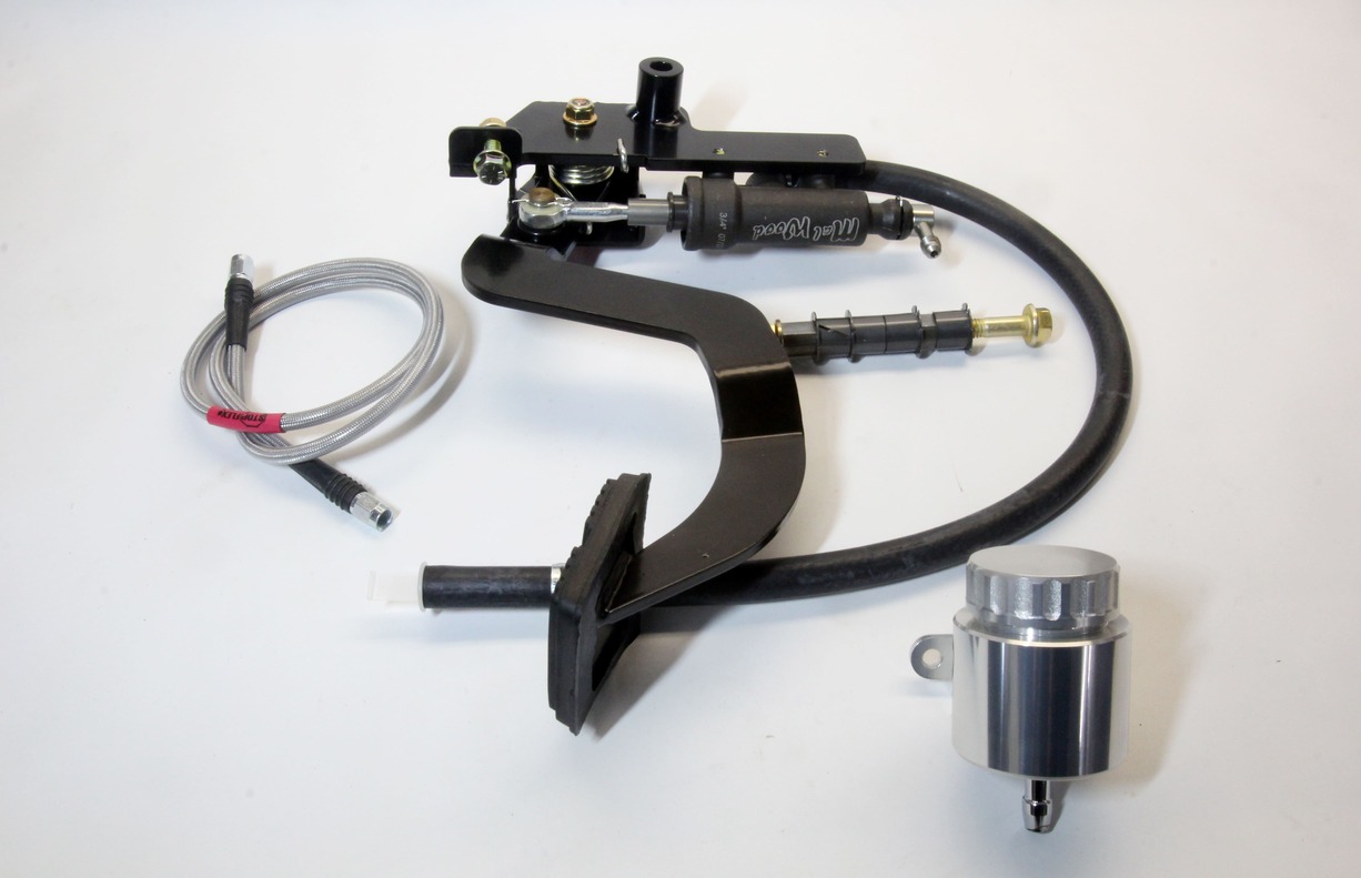
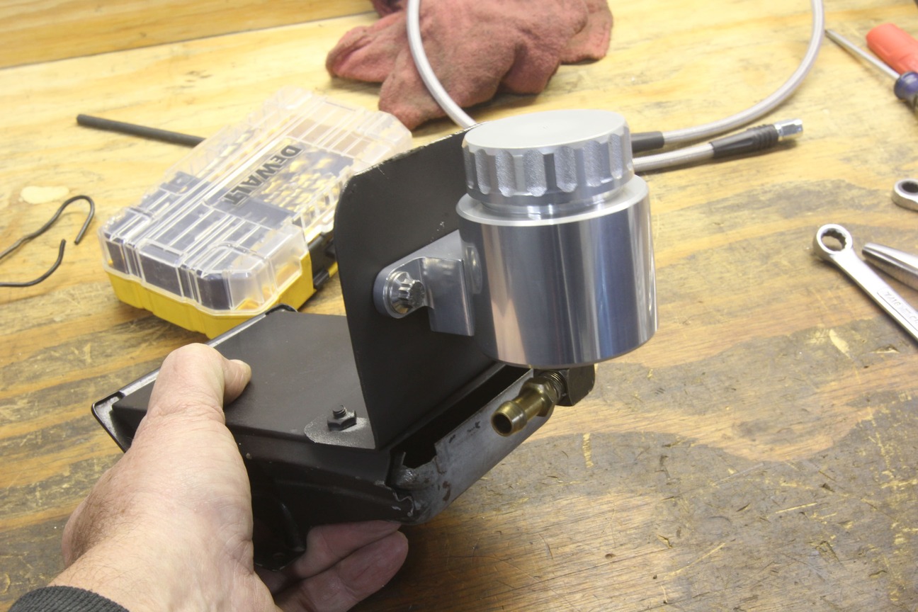
All of these hassles were great reasons not to convert to a hydraulic clutch release system–until now. What it really took was for someone to come up with a better hydraulic master cylinder idea. That’s what MalWood USA has accomplished. MalWood USA is a small company in Ottumwa, Iowa, that has built a better mousetrap. Instead of drilling holes in the firewall to mount a master, it was a far simpler idea to locate the hydraulic master directly to the clutch pedal assembly.
This immediately accomplishes two things: First, now you don’t have to cut holes in your nice, virgin, firewall to mount a clutch master. The MalWood USA idea bolts the master directly to the pedal assembly with the actuator rod factory set, so there is no issue with bad angles that could cause a leak.


This makes the master cylinder installation incredibly easy because the new master cylinder pedal assembly bolts directly in place of the original clutch pedal. Once the pedal is in place, the only major decision is where to mount the clutch master reservoir. If your application has room, you can mount it under the dash as well so that the only access hole in the firewall is for the high-pressure hose routed to the hydraulic release bearing.
The only requirement for mounting the master cylinder reservoir is to place it at a height above the master so that the fluid will gravity feed from the reservoir to the master. That’s it.
We were in the process of assembling our ’66 big-block, four-speed Chevelle and we decided this was a perfect time to upgrade to a hydraulic clutch. What made the decision easy was that we did not have to punch large holes in the firewall. The interior and steering column had not yet been installed in the car, so this made it easier to shoot the photos.
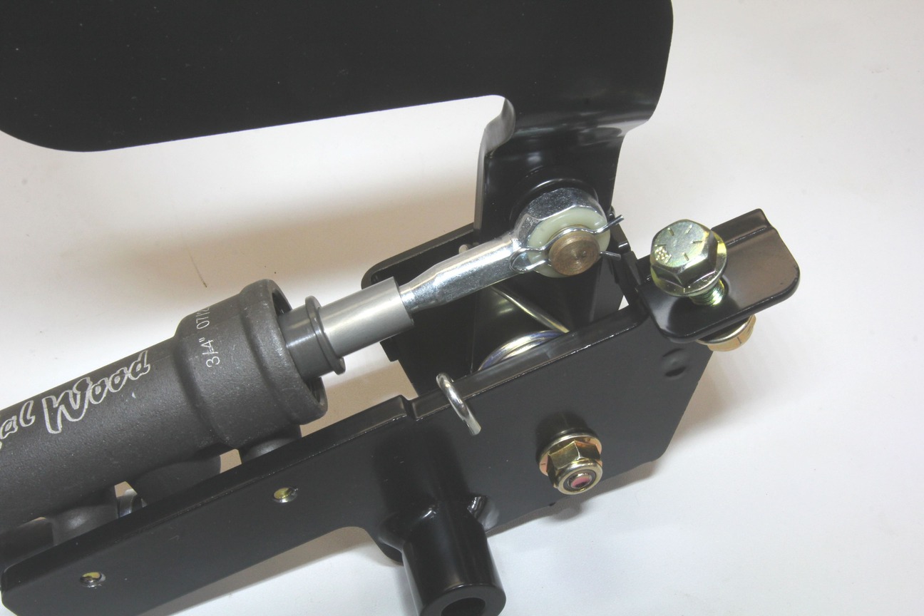
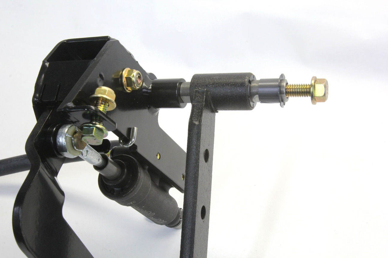
The MalWood USA pedal system is designed to mate directly with the factory brake pedal box and comes with a new cross shaft that replaces the large shaft attached to the original clutch pedal. The MalWood USA system uses the stock pedal box, adding the new clutch pedal assembly with new bushings. The new steel shaft slides through both pedals and uses bolts on each end threaded into the shaft.
Consistent Cranking: Tips on Choosing and Installing a Starter
If you are converting an automatic transmission car to this new hydraulic clutch release system, search around to see if you can find a single, used, manual brake pedal. If not, you will unfortunately have to buy a complete pedal set in order to obtain the correct brake pedal. We searched but did not find a source that offers just the manual transmission clutch pedal by itself.
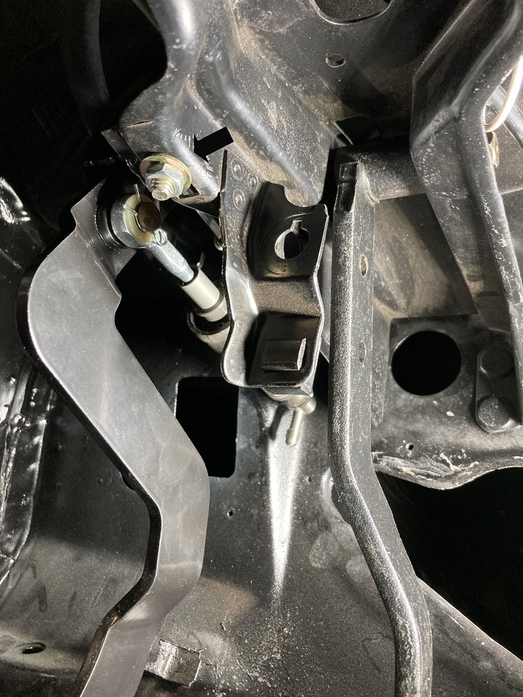
Mounting the new MalWood USA hydraulic pedal is a fairly simple process. We threaded the long grade 8 bolt into the steel sleeve through the hydraulic pedal assembly and removed the small bolt and nut on the flange near the front of the assembly. We also placed two of the new plastic bushings into the original brake pedal. We threaded the new shaft through the brake pedal and then attached the bolt on the other end. At this point, we did not tighten anything until we had the entire system attached.
We then removed the original clutch pedal rubber bumper that was pressed into the original pedal box. This left a rectangular hole in the pedal box that aligns with the bracket bolthole in the MalWood USA pedal assembly.
We pulled the pedal assembly back out of the car because the bolt did not easily fit through the hole because of the powdercoating, which made it difficult to line up the MalWood USA mount with the existing hole in the pedal box.

We simply drilled the hole slightly in the MalWood USA bracket to ensure the bolt slid through the hole properly. Next, to align the pedal assembly hole with the rectangular hole in the pedal box, we had to use a large pair of Channel lock pliers to squeeze the pedal box slightly so the holes lined up. This allowed us to easily slip the bolt through and tightened the nut. This secures the pedal assembly in the car and prevents it from rotating around the pedal shaft.
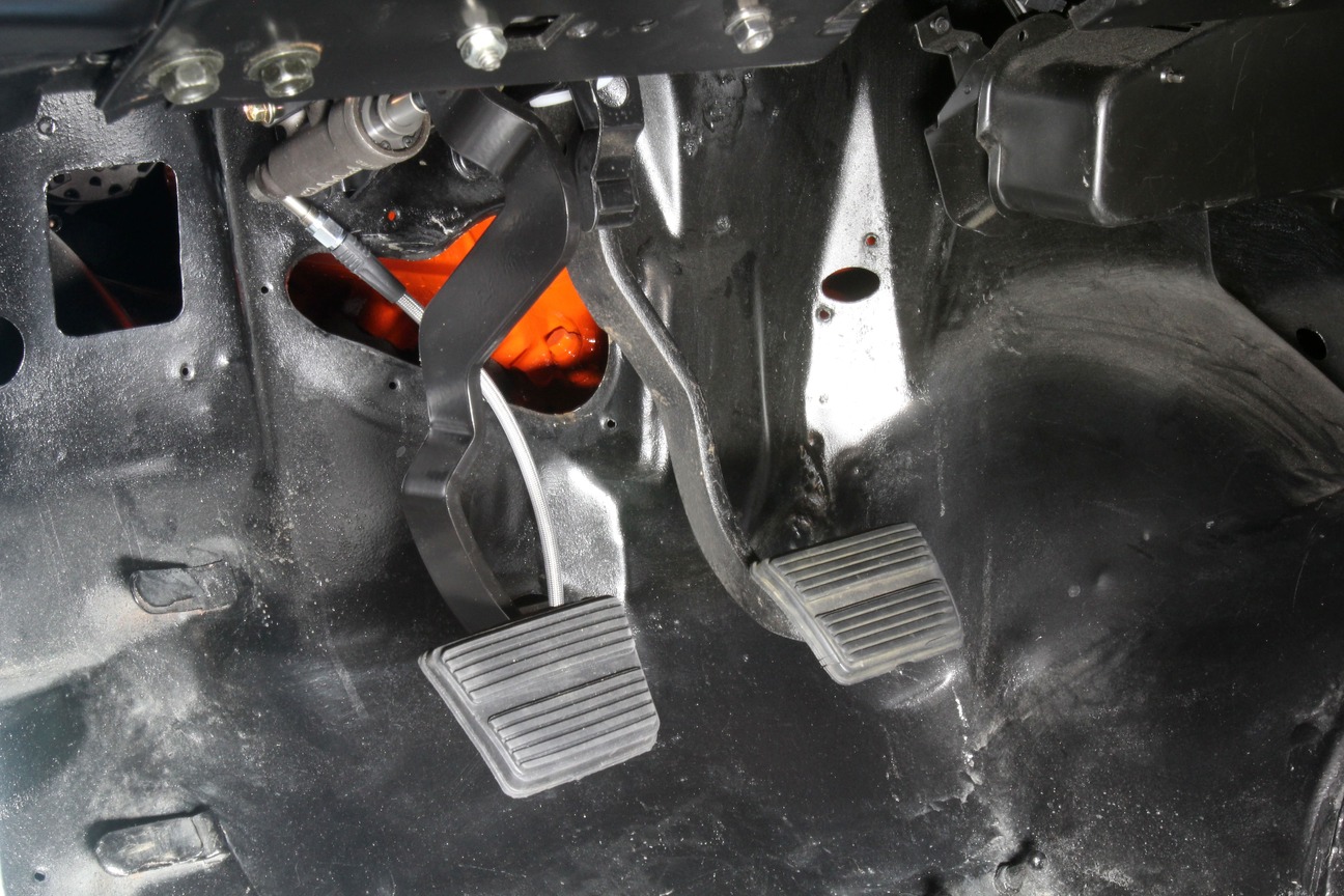
With the hydraulic pedal assembly in the car, the only real challenge of this installation was deciding where to mount the billet aluminum hydraulic reservoir. We decided that rather than drill holes to mount the reservoir on the outboard side of the brake master on the firewall (which is not a bad option), we opted to mount the reservoir under the dash where it would be hidden from view.

We fabricated an aluminum bracket that bolted to the top of the ash tray mount. This might seem a spindly place to locate the reservoir, but the factory ashtray bracket is quite sturdy. This places the reservoir above the level of the master cylinder with enough head room above the reservoir to allow easy access to fill with brake fluid. This can be easily filled using a small rubber suction bulb you can find on Amazon for less than $10.

We then slid the rubber fill hose from the master cylinder over the top of the pedal box and connected it to a right angle fitting we installed in our reservoir to make connecting the hose easier. Finally, we threaded the included high-pressure AN hose from the master cylinder and routed it through the hole in the floor that was originally for the speedometer cable. In our Chevelle, we’re using an electronic speedometer so the speedometer cable hole was a convenient place to route the high-pressure hose. We then made a plate to cover the original mechanical linkage hole that is now not needed.
The focus on this story was to concentrate on the installation of this new MalWood USA hydraulic pedal assembly so we’ll save the details of how to properly install and adjust the hydraulic throwout bearing for another story down the road. But the installation was relatively simple, and we’re now on our way to simpler clutch operation by way of hydraulics.
Vehicle Applications
’67-69 Camaro
’70-81 Camaro
’55-57 Chevy
’63-66 Corvette
’68-82 Corvette
’62-65 Chevy II
’66-67 Chevy II
’68-72 Nova
’64-66 Chevelle and GM A-bodies
’67 Chevelle and GM A-bodies
’68-72 Chevelle and GM A-bodies
’60-66 Chevy and GM trucks
’67-72 Chevy and GM trucks
’73-87 Chevy and GM trucks
’88-94 Chevy and GM trucks
Plus, several Ford and Mopar applications
Source
MalWood USA
(641) 777-0174
malwoodusa.com