The Rocky Hinge taillight conversion kit (PN CHT-01) comes with a wiring harness, mounting plate, and a gas cap and filler tube. The unit can be operated by a dash-mounted switch or remote control.
How to Install an Electric Gas Filler Taillight Kit
More than 100 years ago, when automobiles first began to be mass produced, you’d fill your gas tank via an exterior cap and filler tube. Over the decades, gas caps and filler tubes moved around to different locations on both the exterior and interior of a vehicle but, in the ’40s and ’50s, a handful of cars hid them from sight altogether.
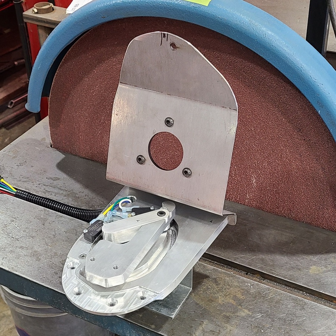
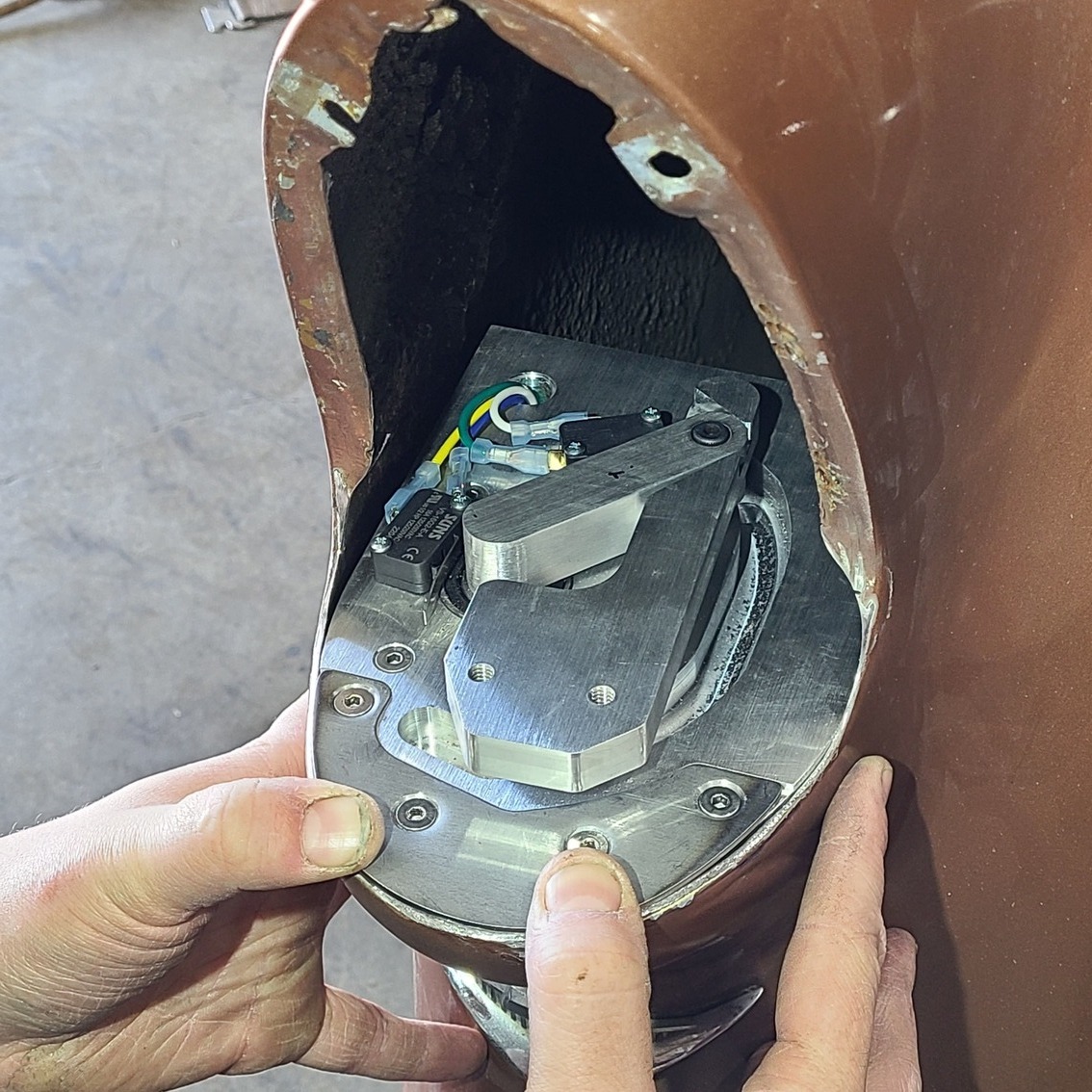
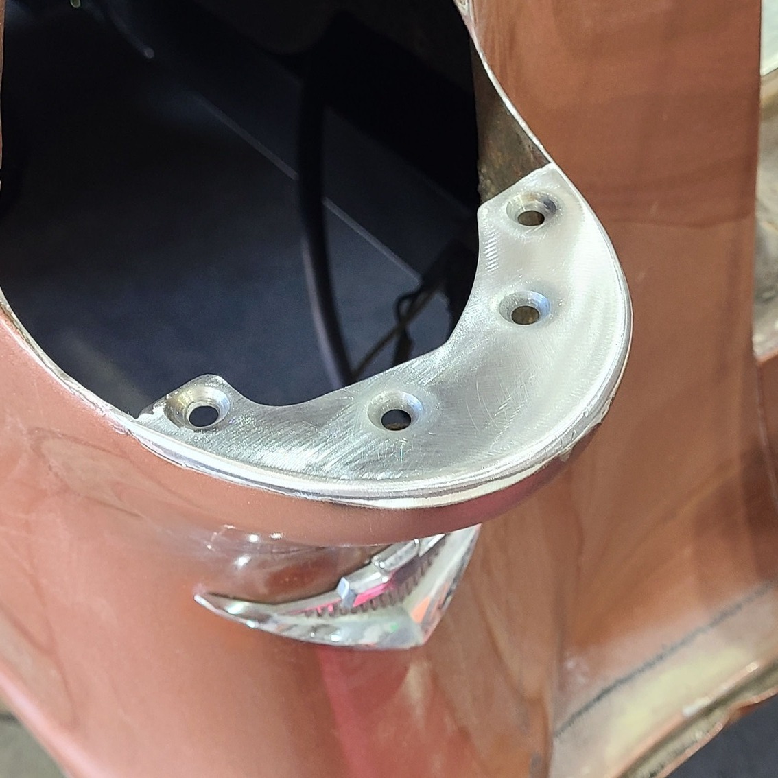
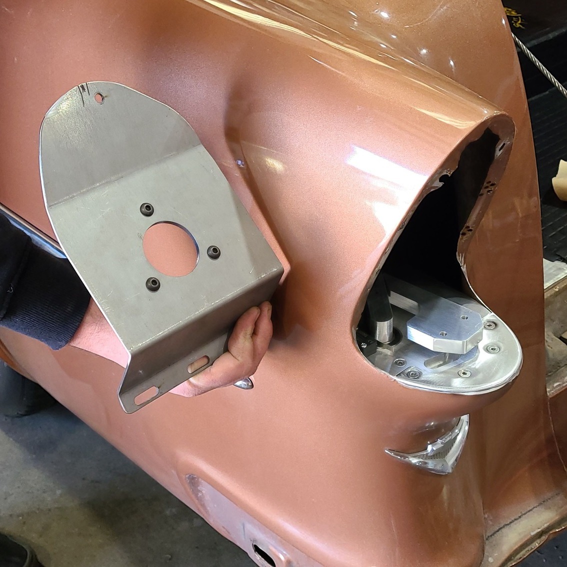
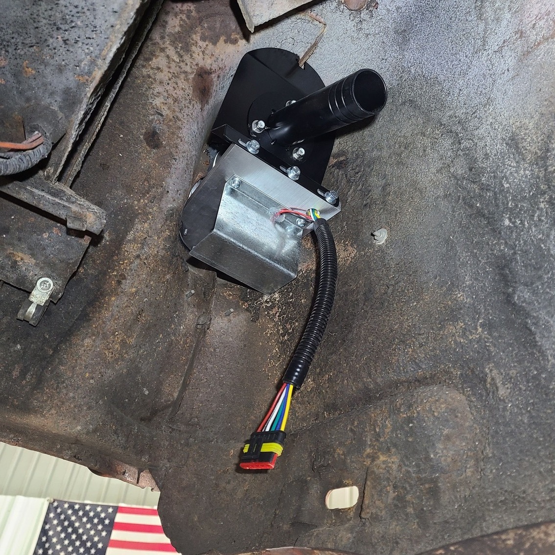
The two main pieces of the kit are the horizontally mounted, motorized base and the vertical gas filler tube support plate.
The ’40s-era Cadillac used a flip-up taillight to hide the cap and filler, but soon Imperials, Oldsmobiles, Nashes, Continentals, and even a Peugeot would give the design a go.
Even Chevrolet’s fullsize passenger vehicle, the Bel Air, would use the feature on their ’56 model, but by the ’70s, when more stringent safety standards were enacted, the gas filler moved from behind the rear license plate or apron to a vehicle’s quarter-panel.
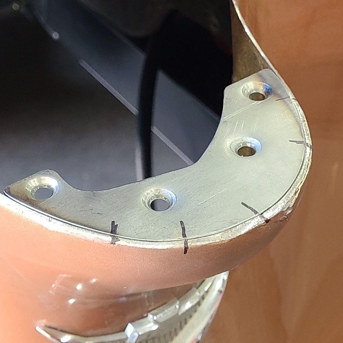
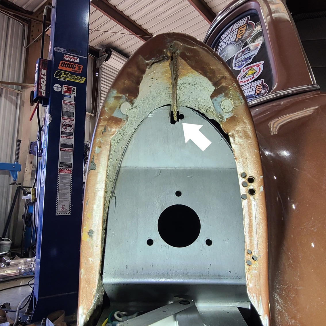
The motor baseplate will be secured to this horseshoe-shaped plate that will be welded to the wagon’s taillight opening.
For vintage-minded folks who not only want the nostalgic look of a hidden gas filler behind their ’55 Chevy but want it to motorize the operation as well, then you should know about Rocky Hinge, based in Girard, Ohio.
Formed in 1996, Rocky Hinge manufactures more than 50 types of vent, trunk, and hood latches, bear claws, door hinges, folding hood props, door lock mechanisms, and more—many of which are electrically powered.
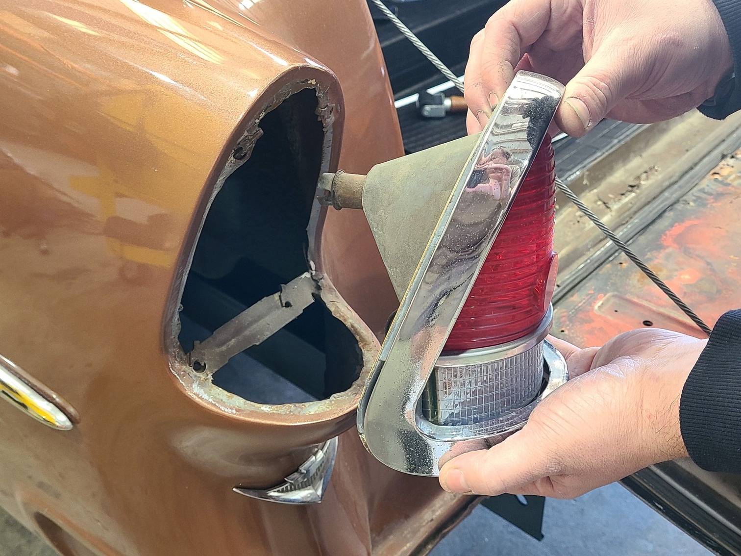
Disassembly begins with the stock taillight housing being removed from the vehicle.
Recently, Orange County Hot Rods (OCHR) in Corona, California, installed one of the Rocky Hinge ’55 Chevy taillight conversion kits on a ’55 Chevy Handyman wagon. However, the Rocky Hinge kit is made for the ’55 Chevy passenger car line of vehicles, so some modifications needed to be made to both the wagon body and the kit to make everything fit right. The thing that took the longest in doing these modifications was the miniscule adjustments to two mounting screws that set how the unit fits in its hole during the closing operation—critically important adjustments. OCHR took it all in stride and got the job done, so follow along and see how they did it.
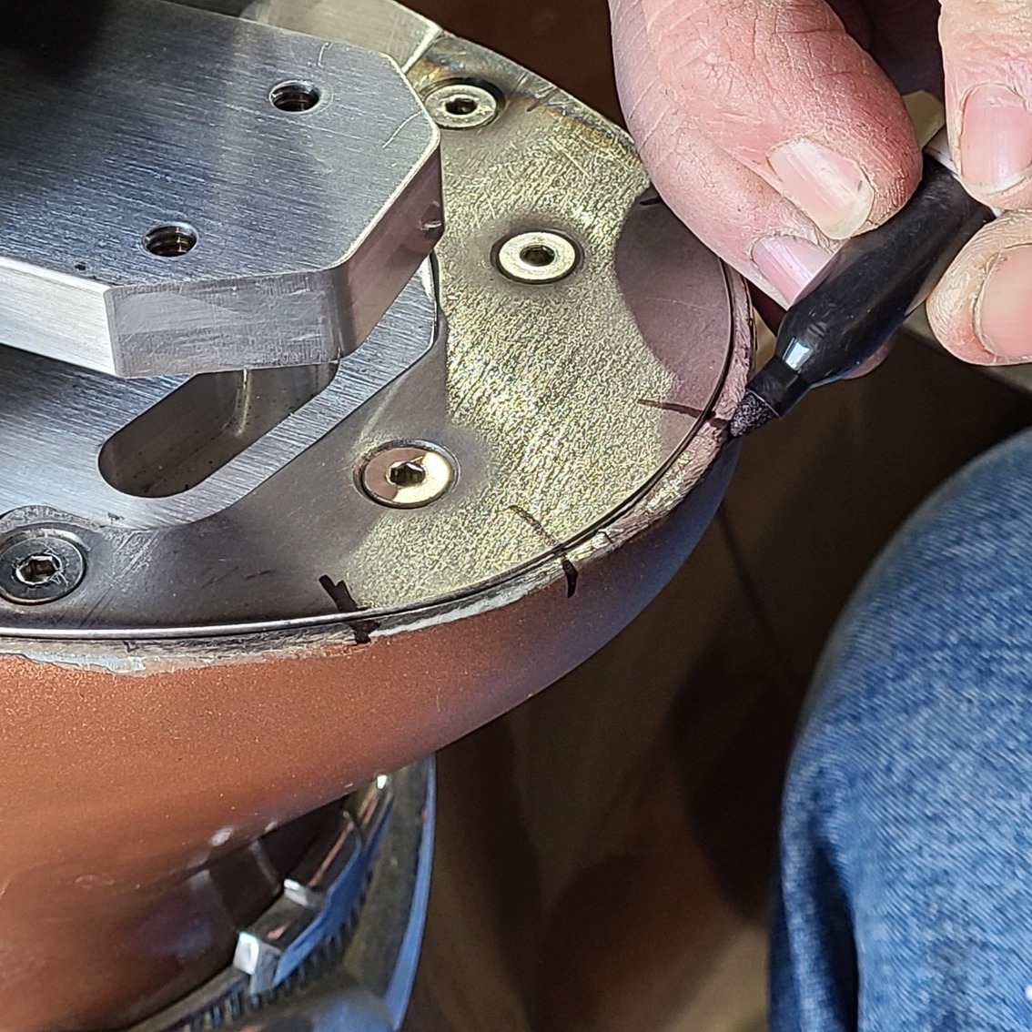
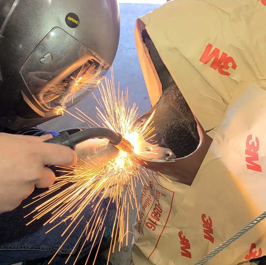
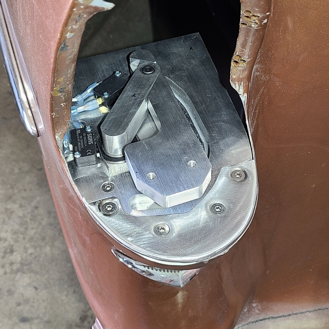
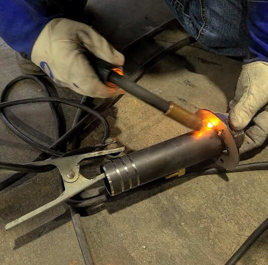
The horseshoe plate is laid over the lower portion of the opening, which is marked to show how much material will need to be removed. The factory horizontal housing support bracket will also need to be removed.With the horseshoe bracket screwed in place to the motorized base, the unit is fit into place and pulled rearward for a flush fit to the opening. (As you install and remove the unit multiple times during this part of the build, you’ll need to support it in the opening somehow—OCHR used small magnets to keep it from falling inward.)Fine-tuning the base’s fitment meant marking the edge of the opening that needed to be ground away to ensure a tight fit.The base and opening should have location marks so the unit will always be fitted to the exact same spot and orientation each time.Using magnets underneath to hold it in place, the horseshoe bracket is set in place.After wrapping the wagon’s quarter-panel in 3M Welding and Spark Deflection Paper (because the car is painted) and making sure it is level, OCHR’s Nic Cantrell MIG welds the plate in place.After some grinding and sanding, the mounting plate is now ready for the base unit.The base section is reinstalled and, by gently pulling on the motorized arm, you can see how far the arm will extend.
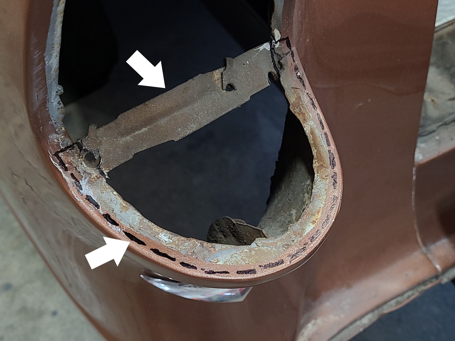
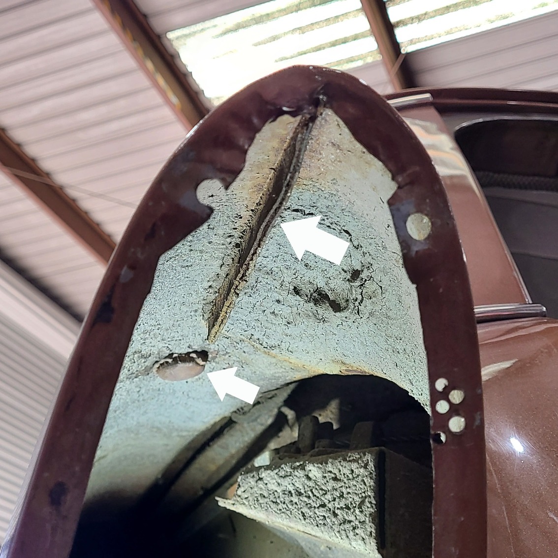
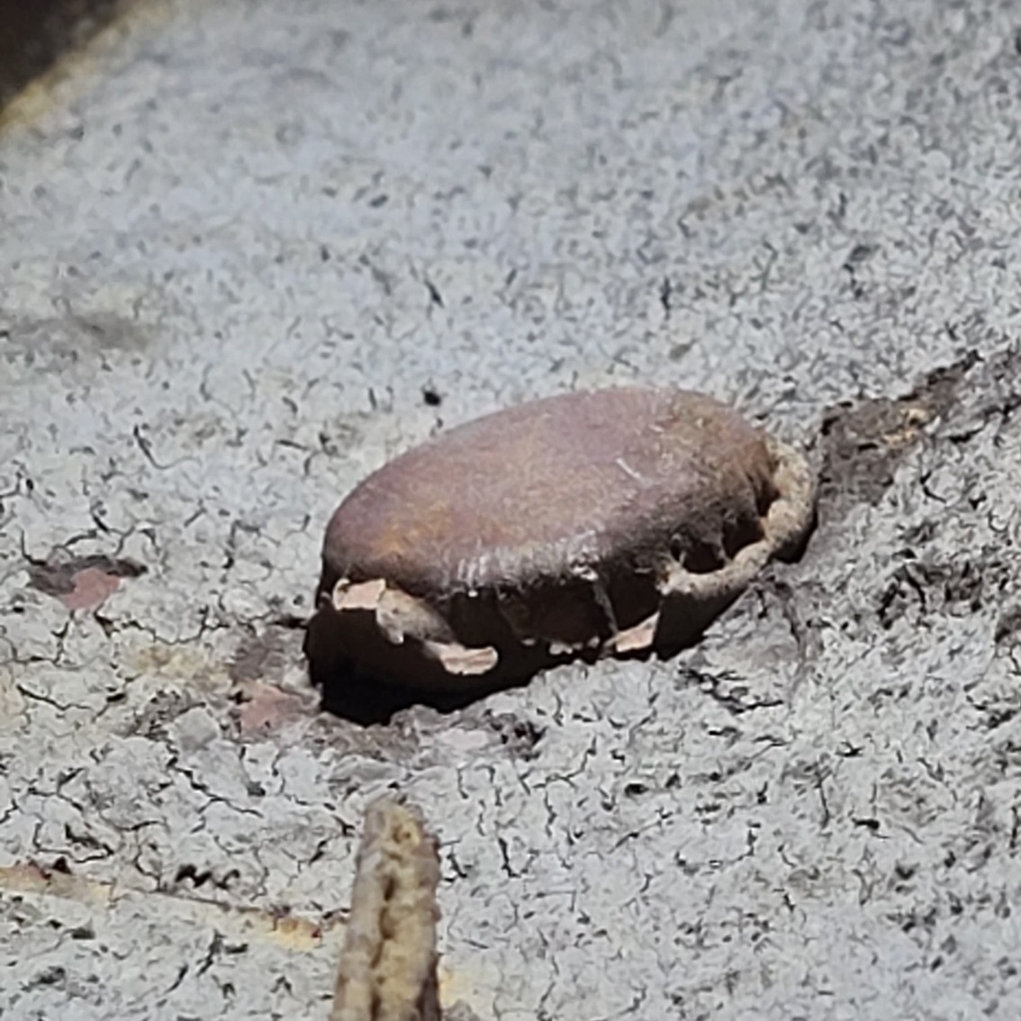
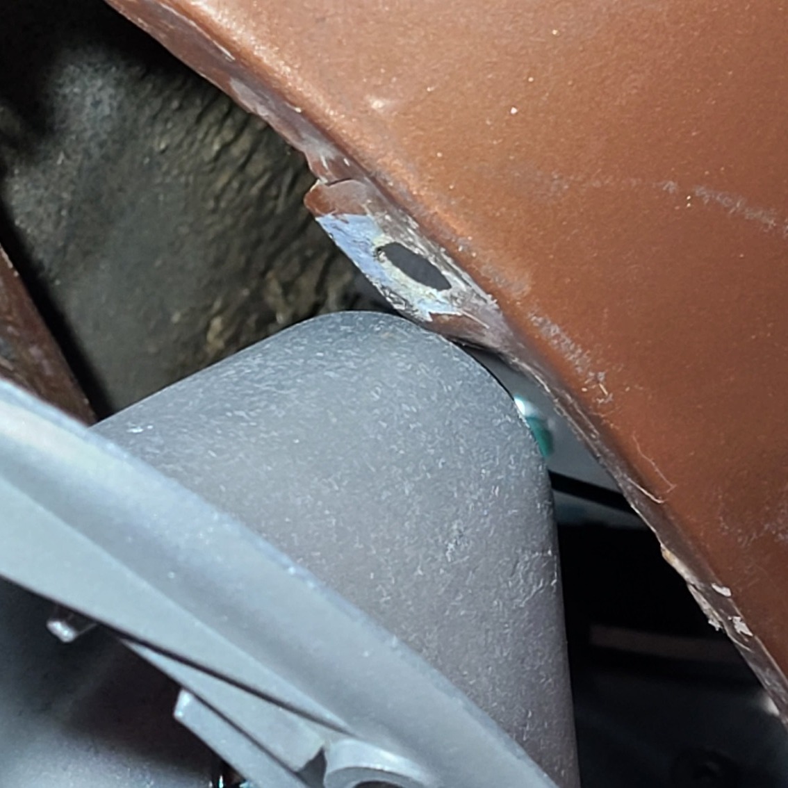
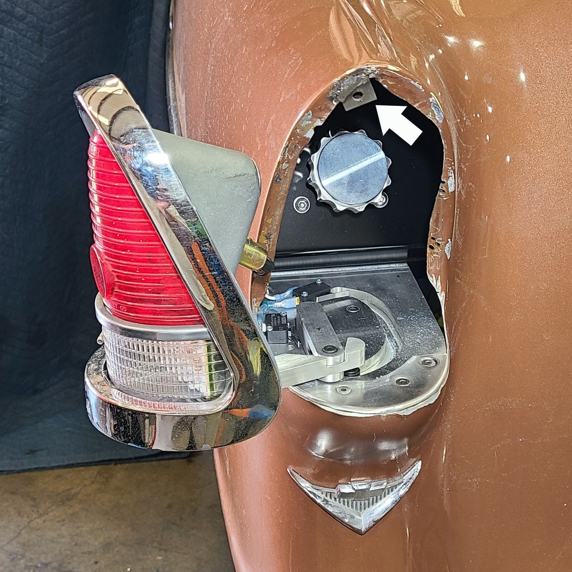
This Handyman wagon body has this factory-welded seam (large arrow) that interferes with the gas filler plate that will be installed next. The smaller arrow points to the upside-down bottle cap that was inserted into the rear antenna hole (on both quarters) by a previous bodyman and then covered with body filler.
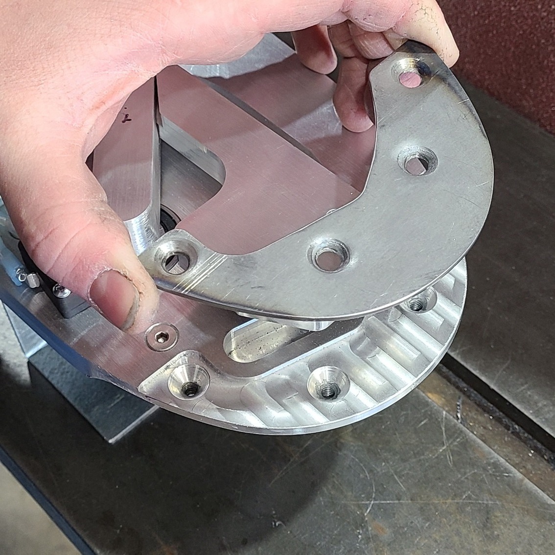
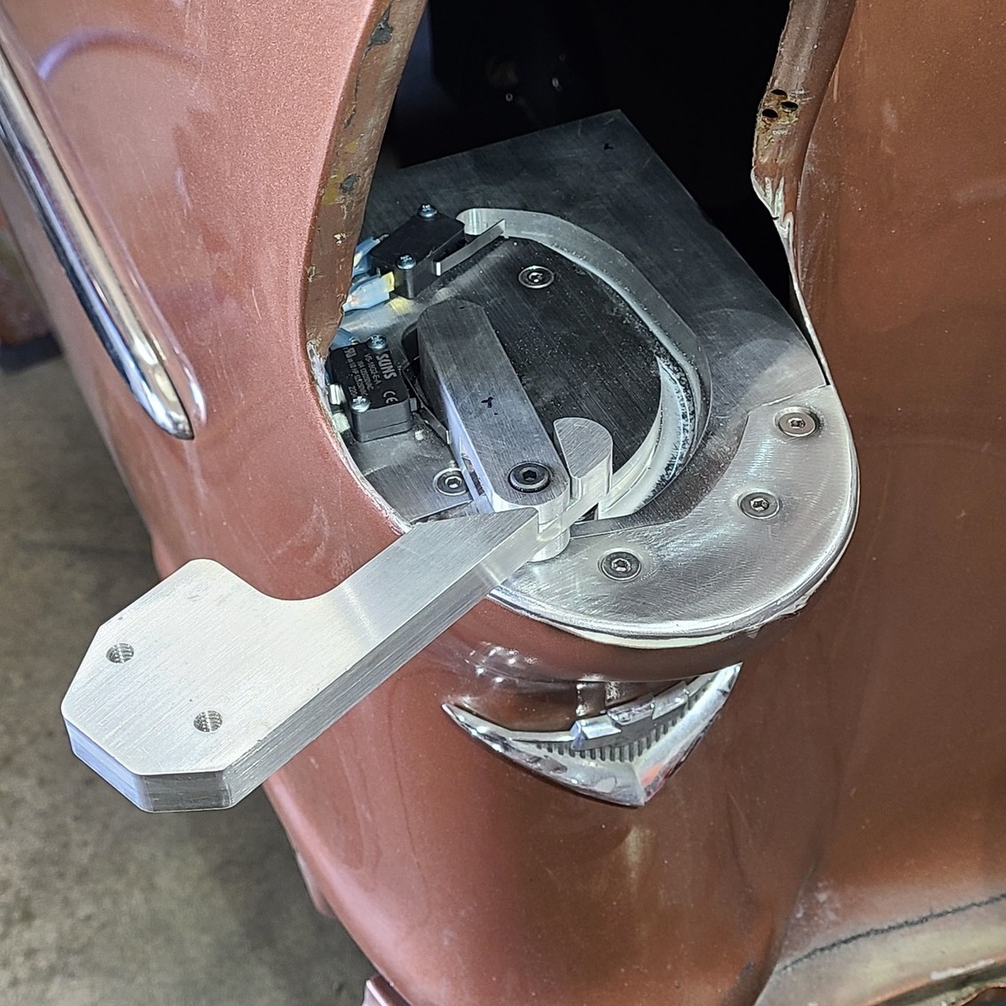
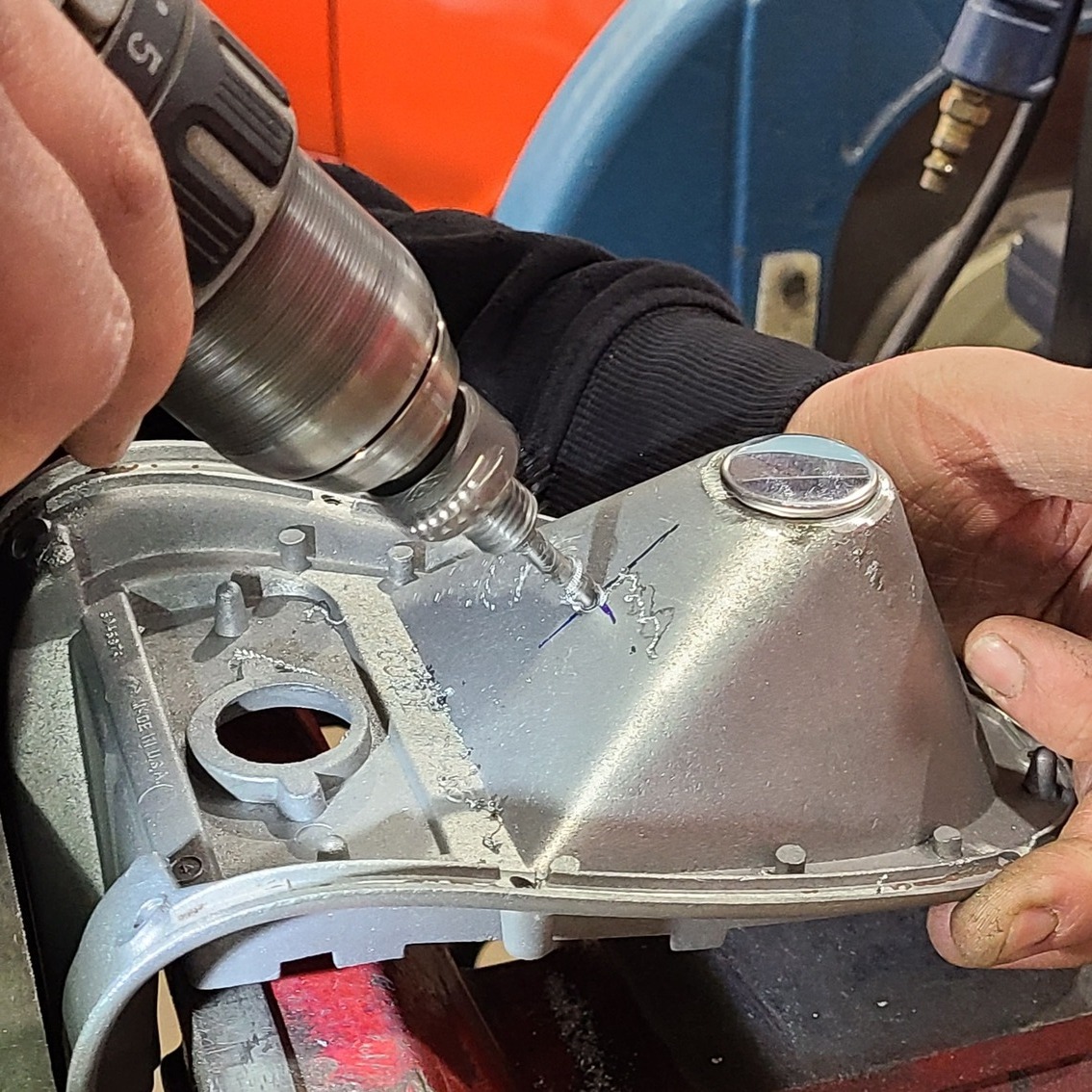
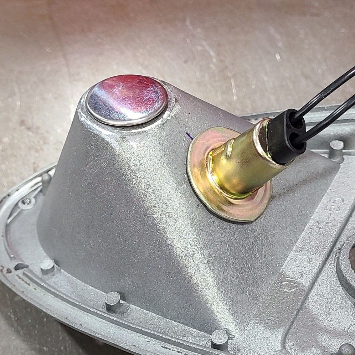
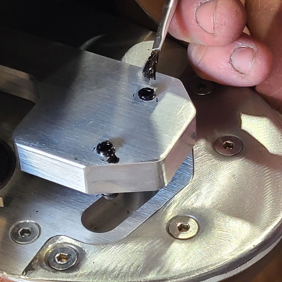
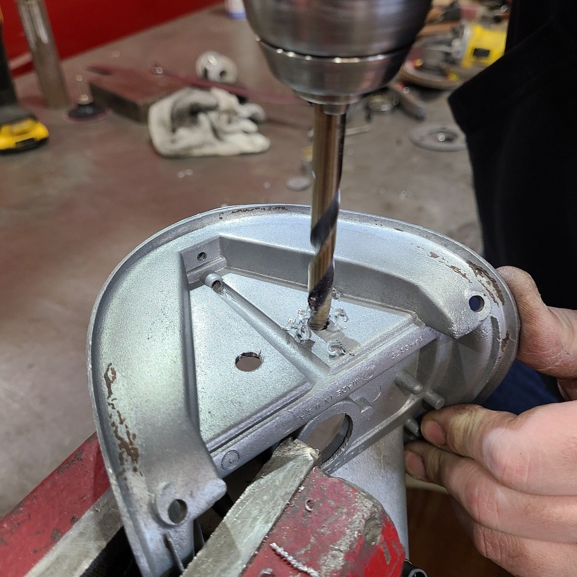
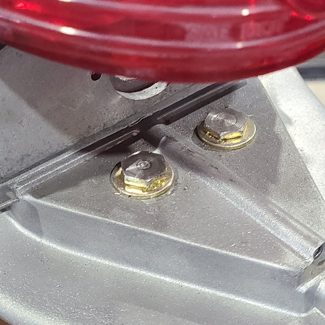
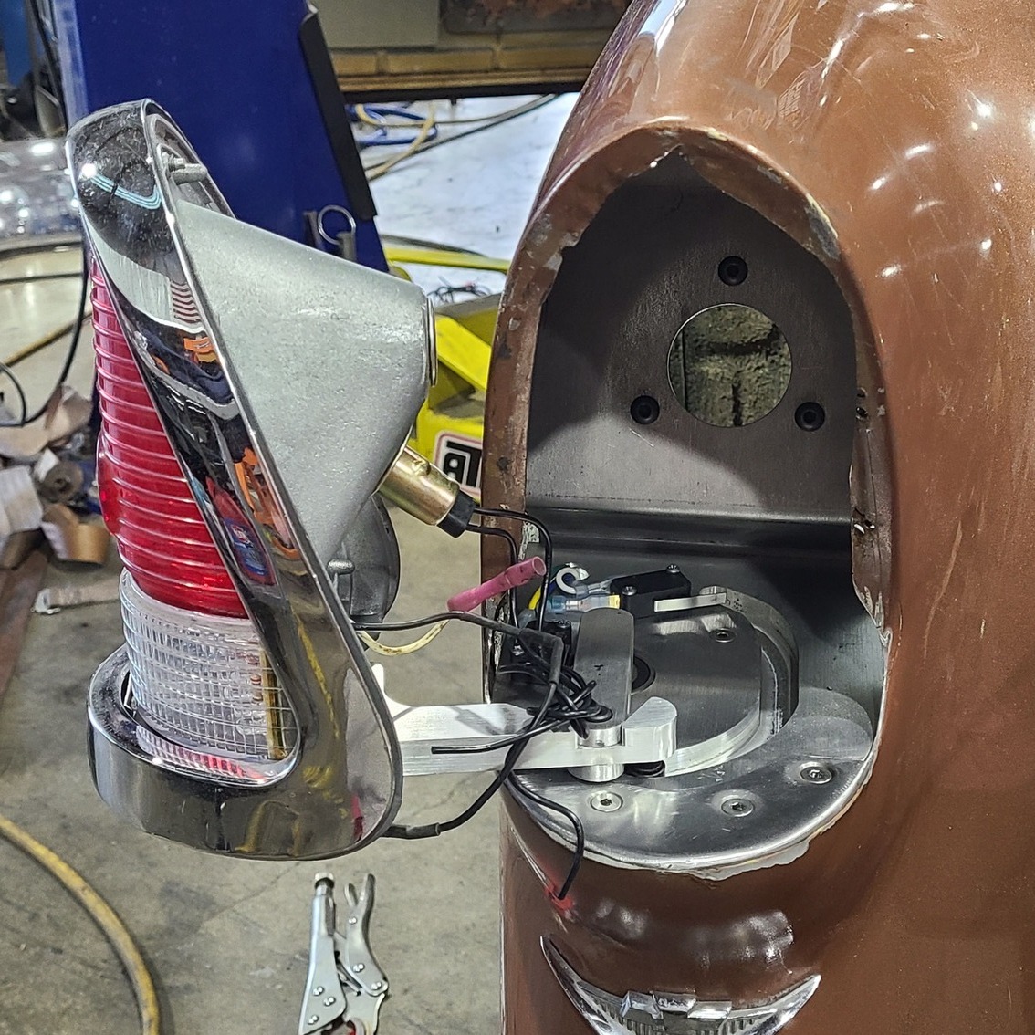
This is the orientation of the gas filler tube mounting plate to the motorized base plate.Rocky Hinge supplies a mounting tab in their kit to help secure the filler plate’s location, but it is located exactly where the body seams are, so it had to be removed and the plate notched for clearance.The stock taillight bulb holder will hit the new gas filler cap so it must be removed and relocated.The factory bulb hole is capped off and the new bulb location is marked and drilled.The new LED light bulb is installed here.To know where the taillight assembly will attach to the arm, Cantrell marks headless Allen screws with some black ink and then sets the housing back in place, thus marking the location on the housing.Cantrell then drills out the marks and attaches the housing to the arm.After checking the complete swing of the arm, Cantrell finds the housing barely rubs the upper right edge of the taillight opening, so he’ll grind that away until it doesn’t interfere with the housing’s movement.These two mounting screws for the housing are critically important because the slightest adjustment in them determines how well the housing will fit against into the taillight opening. Washers will determine height adjustments.At this stage the entire taillight assembly can be gently pulled into and out of the opening.After fitting the gas filler mounting plate and tube into the unit, Cantrell marks the diagonal angle of the mounting plate against the tube and then tack welds it in multiple spots.The finished assembly in place from the inside, with only wiring needed to complete the procedure.Note the little locating tab Cantrell added that fits to a nub on the back of the taillight housing, which ensures proper alignment when the unit is closing tight against the quarter. Now the finished taillight housing will swing open and shut with a flip of a switch.
We use cookies to ensure that we give you the best experience on our website. If you continue to use this site we will assume that you are happy with it.


 comes with a wiring harness")