
Understanding the Terms, Sensors, and Systems
By Ryan Manson – Photography by the Author
Electronic Fuel Injection (EFI) systems can be a daunting mystery of sensors, wires, and components to those of us with a more “analog” background. Tuning by turning screws or swapping jets might seem second nature to some, but when it comes to fuel maps, electronic sensors, and laptop tuning, it starts to seem more like rocket science. But a familiarity to the science behind how an EFI setup works isn’t completely necessary to understand the gist of such a system. A basic understanding of the sensors involved and what they do and how they communicate with the computer (ECU) to provide the necessary fuel requirements can go a long way to gaining a grasp of how a modern EFI system works.
Like a carburetor measures and delivers fuel to a hungry engine via jets, ports, valves, metering blocks, and so on, an EFI system does the same by using myriad electronic sensors and a sophisticated computer (ECU) that gathers the information from said sensors, collates it, and compares it to a preprogrammed fuel map. Using the gathered specifics, the ECU determines when and for how long each fuel injector should open (known as pulse width). At idle, each fuel injector fires at a specific time (as programmed in the ECU) for a very short pulse width since the engine needs very little fuel to maintain a 14:1 air/fuel ratio. As engine speed increases, so does each injector’s pulse width, keeping up with the engine’s increasing fuel needs. The amount of time the fuel injector is opened is known as its duty cycle and is measured as a percent. So, if an injector has a 50 percent duty cycle, that injector is being held open an equal amount of time as it’s being held closed. A duty cycle over 80 percent is not recommended as that injector is reaching its maximum capacity and will soon become “static” or held wide open. This can result in a lean condition that can cause catastrophic engine damage. It should be mentioned that on most EFI systems, the fuel injectors operate using a “firing order” similar to an ignition system, with each injector opening for the same duration (duty cycle) at a predetermined time. That said, if one injector is reaching a certain percentage duty cycle, it can be assumed that the other injectors are doing the same. So, when it comes to duty cycle, it’s typically referenced to as a single reading for the system. In most cases, decreasing the duty cycle to a more manageable number is as simple as increasing injector size and adjusting the tune to suit.
When it comes to modern EFI systems, the two most common methods of metering and maintaining the proper air/fuel ratio are speed density and mass airflow. Most aftermarket EFI kits utilize the speed density method, as it’s the simpler of the two when it comes to packaging and allows for a more user-friendly installation. Mass airflow, on the other hand, while technically more accurate, can be difficult when it comes to retrofitting into an older muscle car due to specific air inlet requirements. Let’s take a closer look at the two different methods and how they control the fueling requirements of a modern engine.
ACP

Section 1:
Speed Density
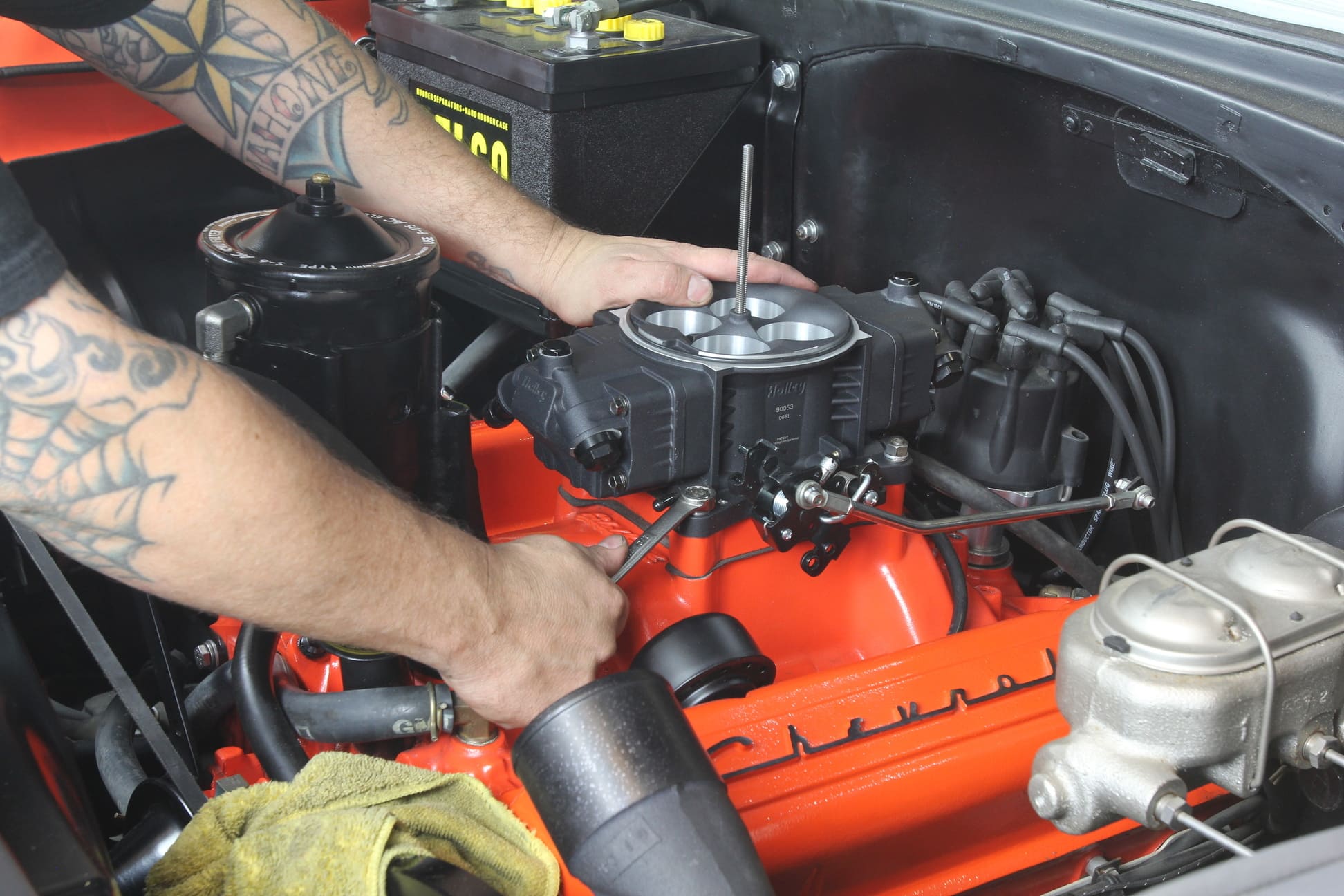
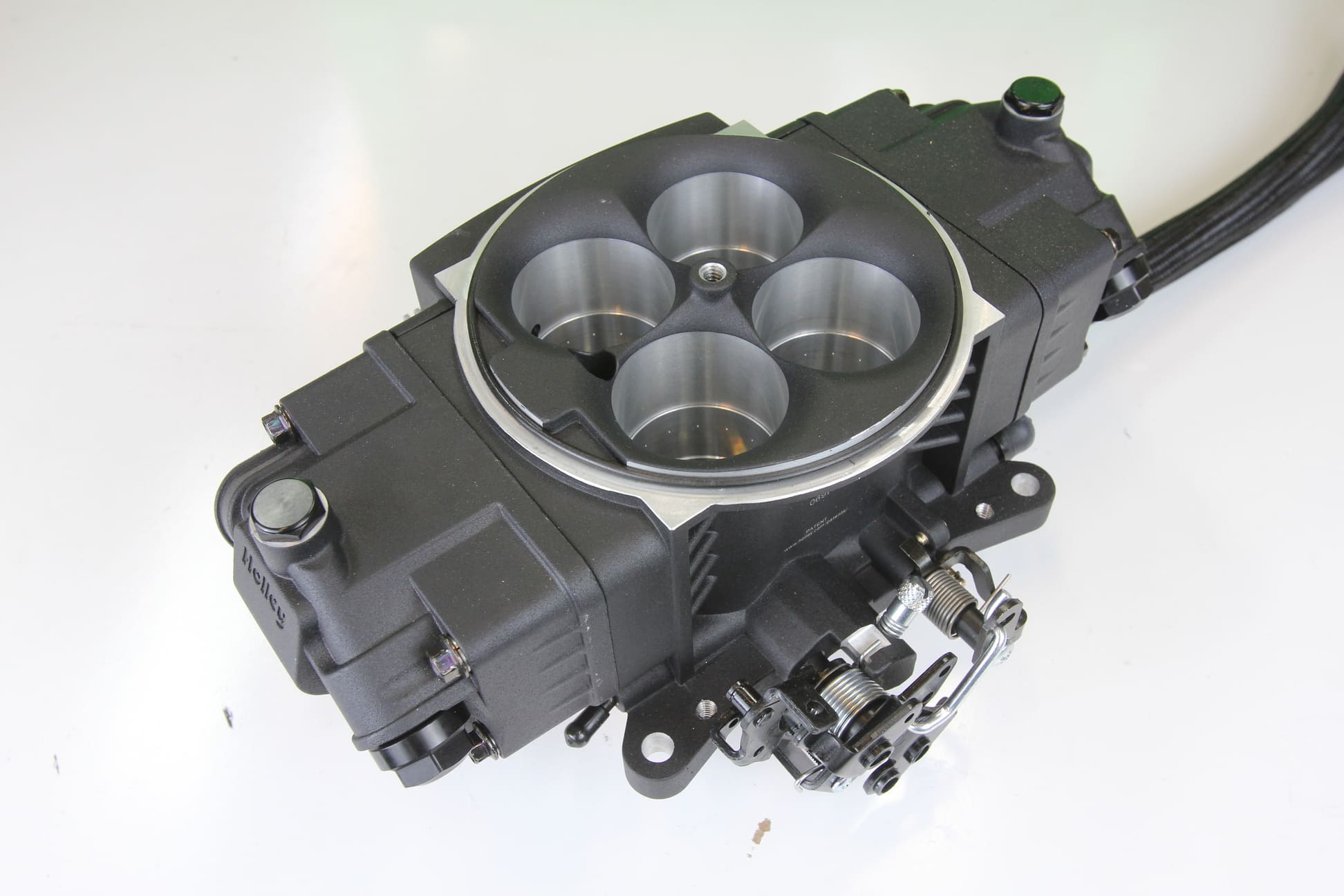
Speed density metering is the simpler of the two and determines fuel needs based on engine speed and air pressure. A manifold absolute pressure (MAP) sensor mounted on the intake or throttle body reads the intake manifold’s air pressure and, in conjunction with engine speed (rpm) read from the ignition coil or crank position sensor, this information is processed by the ECU and compared to a preprogrammed data table to determine engine airflow and, hence, fuel needs. Speed density metering is common among aftermarket four-barrel throttle body-type EFI systems like this Holley Super Sniper due to its simplicity of installation.

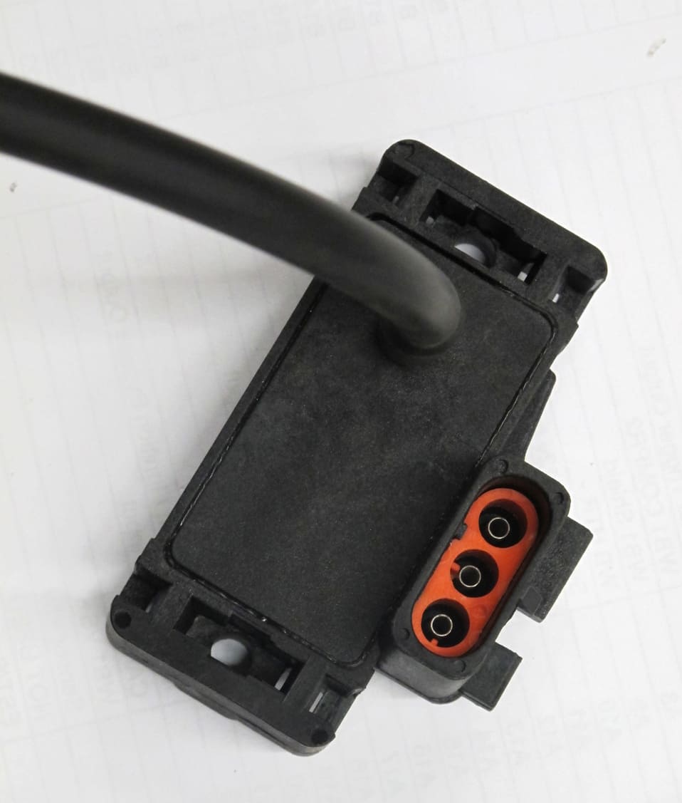
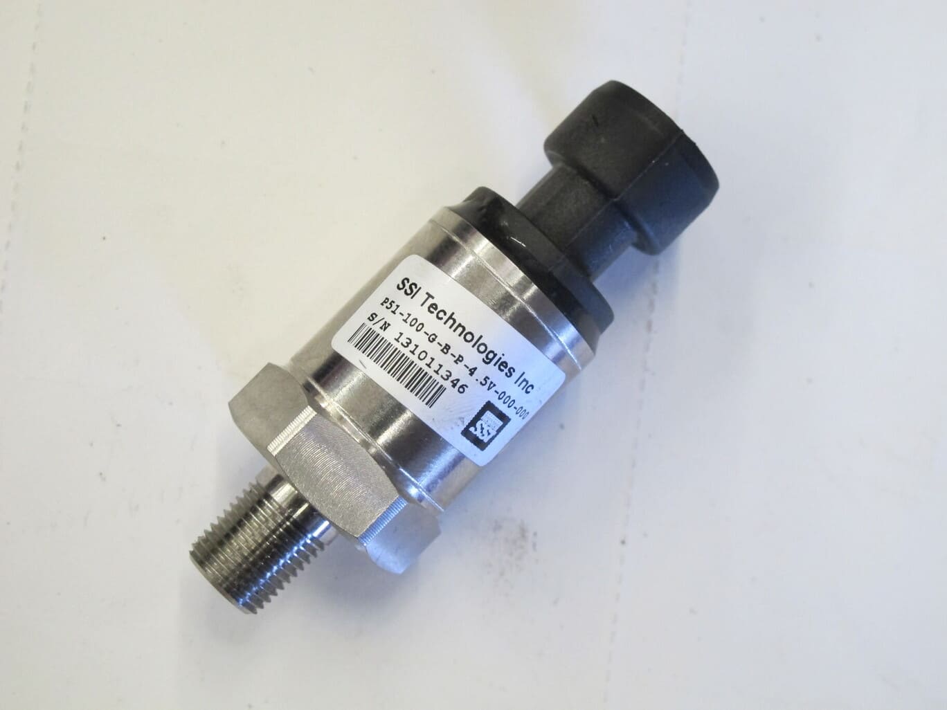
Manifold Absolute Pressure (MAP) Sensor
Single bar MAP sensors are typically installed from the factory on naturally aspirated applications. These sensors report barometric pressure times one, which is approximately 14.7 psi (atmospheric pressure). Boosted applications require a MAP sensor with more range since the turbo- or supercharger is increasing the pressure inside the intake. The amount of boost being introduced dictates the range of the MAP sensor. For example, a blower making 8 pounds of boost can see intake pressures around 22.7 psi, requiring a 2-Bar MAP sensor, which is capable of reading up to twice atmospheric pressure (29.4 psi).
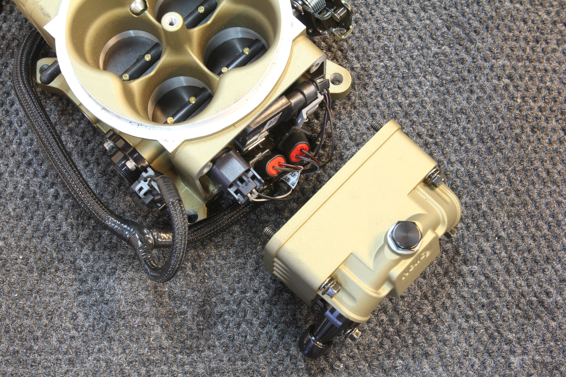
Here’s a Holley Terminator Stealth throttle body with the side bowl removed showing the hidden fuel injectors, MAP sensor, and fuel pressure sensor. The sensor on the left side is the throttle position sensor.
Section 2:
Mass Airflow
A mass airflow metering system uses a mass airflow (MAF) sensor mounted in front of the throttle body to determine engine airflow and uses a preprogrammed data table to determine an engine’s fuel needs based on the noted airflow. The MAF sensor measures airflow using a heated wire that maintains a determined temperature that is above ambient inlet air temps. Air passing over the wire draws away the heat, the change in temperature is computed by the ECU, and the amount of current needed to heat the wire back up to its operating temp is converted and calculated into the amount of airflow entering the inlet tract. Unlike speed density, mass airflow measures actual airflow, thus making it a more precise and flexible design when it comes to moderate engine changes (cam swap and so on). The need for additional plumbing in front of the throttle body to mount the MAF sensor and an external airbox/filter makes MAF metering designs slightly more cumbersome and difficult to install in a tight package, such as a vintage muscle car.

Mass Airflow (MAF) Sensor
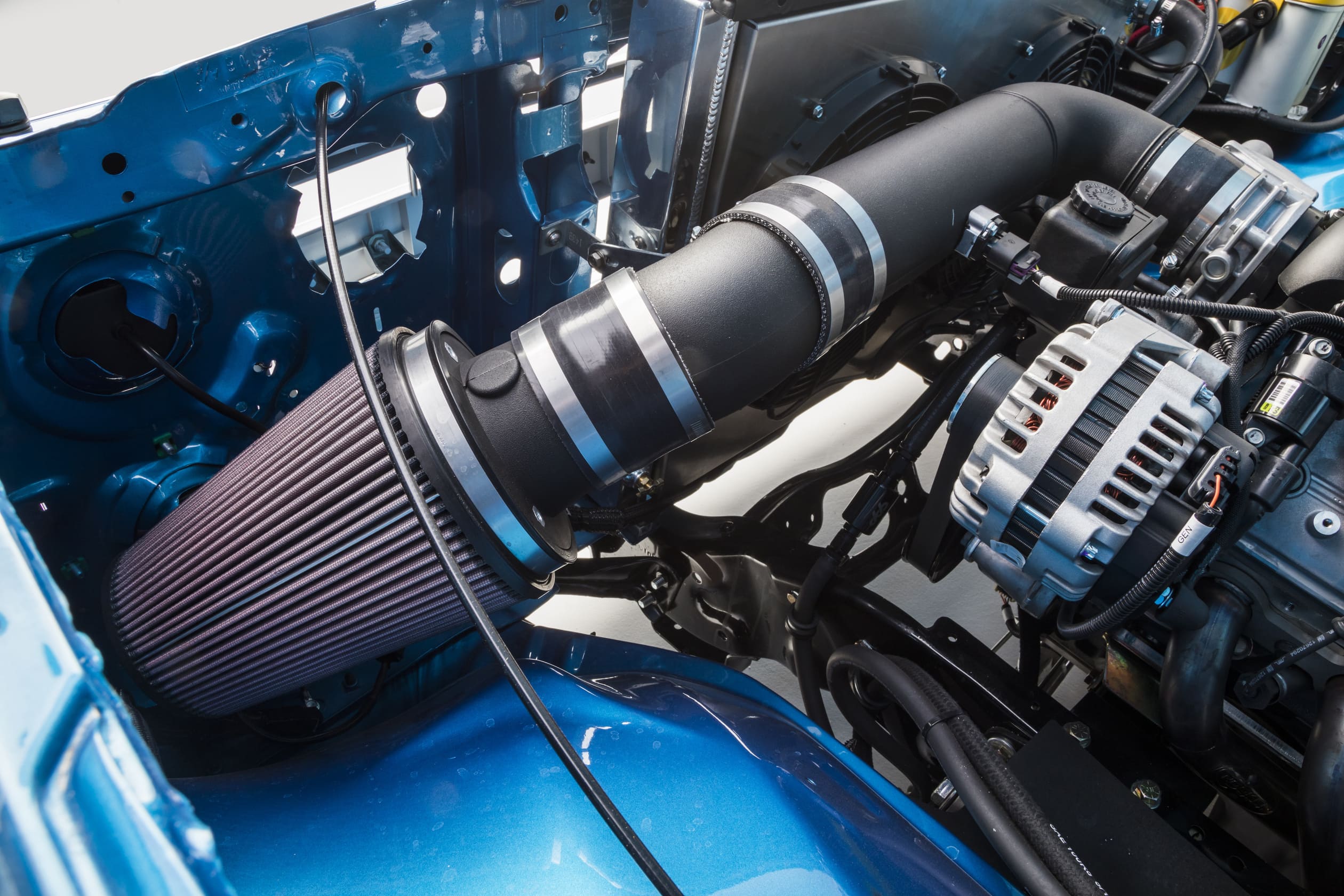
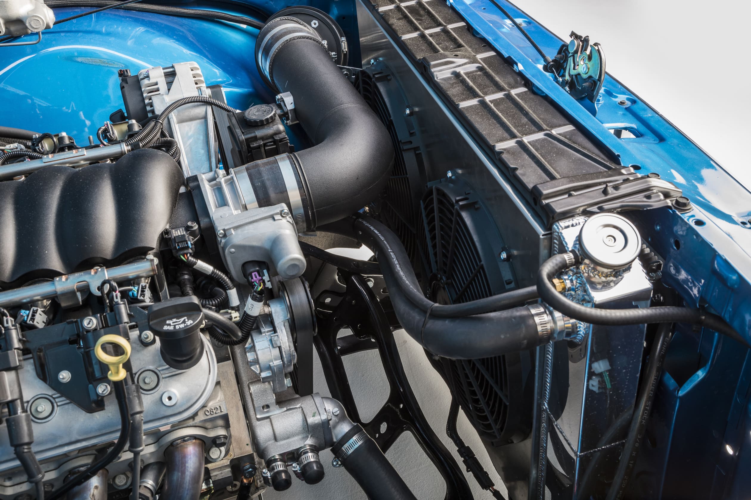
A mass airflow system requires the MAF sensor to be mounted a certain distance from the throttle body in the inlet tract and can make for a difficult installation in a tight engine compartment. In this example, the MAF is installed in front of the alternator in the straight section of the inlet tract.
Section 3:
Additional Sensors
In addition to each system’s specific sensors, there are a handful of other sensors that may or may not be used, depending on the application, brand, and so on. These sensors work in conjunction with each other to provide different information to the computer to aid it in creating the best overall picture as it relates to the engine’s fuel, and even ignition, needs. Here’s a quick look at some of those sensors, where they are typically located, and what they do:

Throttle Position Sensor (TPS)
A throttle position sensor is mounted on the throttle shaft of the throttle body and is used to determine throttle position and provide further information to the ECU to determine engine airflow.

Intake Air Temperature (IAT) Sensor
An intake air temperature sensor measures the temperature of the incoming air stream in the intake manifold to determine changes in the air density.
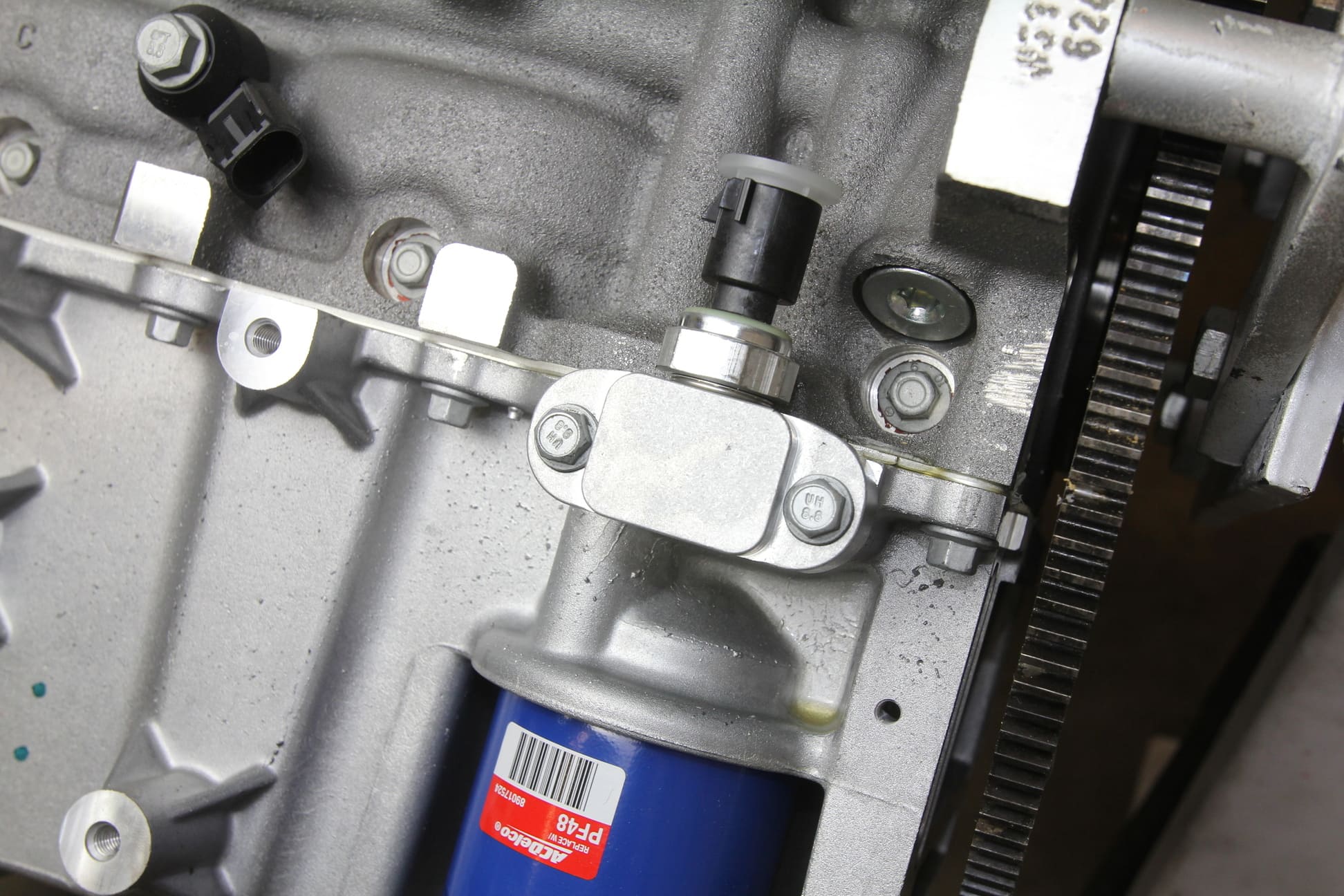
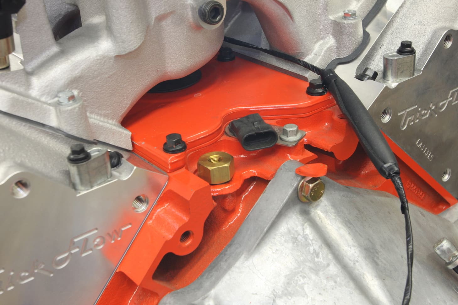
Oil Pressure Sensor
Some OE and aftermarket EFI systems can monitor the engine’s oil pressure and make necessary adjustments to protect the engine in the case of a low-pressure situation (go into “limp mode” for instance). Most GM engines feature a port at the top of the rear of the block that accepts an oil pressure sensor, while LS-series engines have a block-off plate just above the oil filter that can be modified or replaced with a different plate that will also accept an oil pressure sensor.
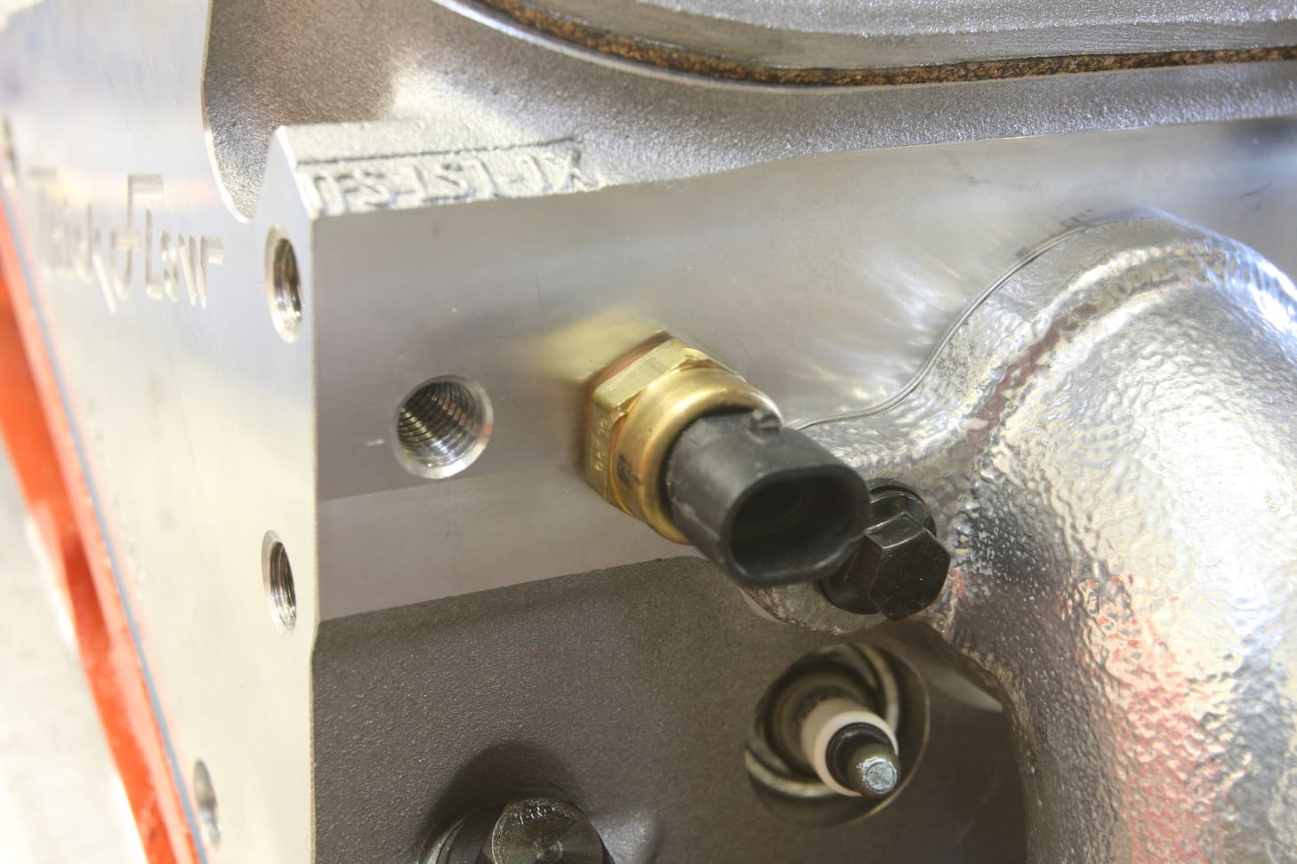
Coolant Temperature Sensor (CTS)
The amount of fuel that an engine requires changes due to its operating temperature, so it’s necessary for the EFI system to know the temperature of the engine’s coolant to determine how much fuel the engine needs. Cold start situations require different fueling requirements as opposed to hot start situations, for example. Many aftermarket EFI systems will not go into closed loop until the engine reaches a set operating temperature, so a CTS is very important for proper, reliable operation. Electric fans controlled by the EFI ECU are also dependent on accurate cooling temps to turn on and off at the proper time. Coolant temperature sensors are usually mounted in the intake or cylinder heads with direct access to the coolant passage.

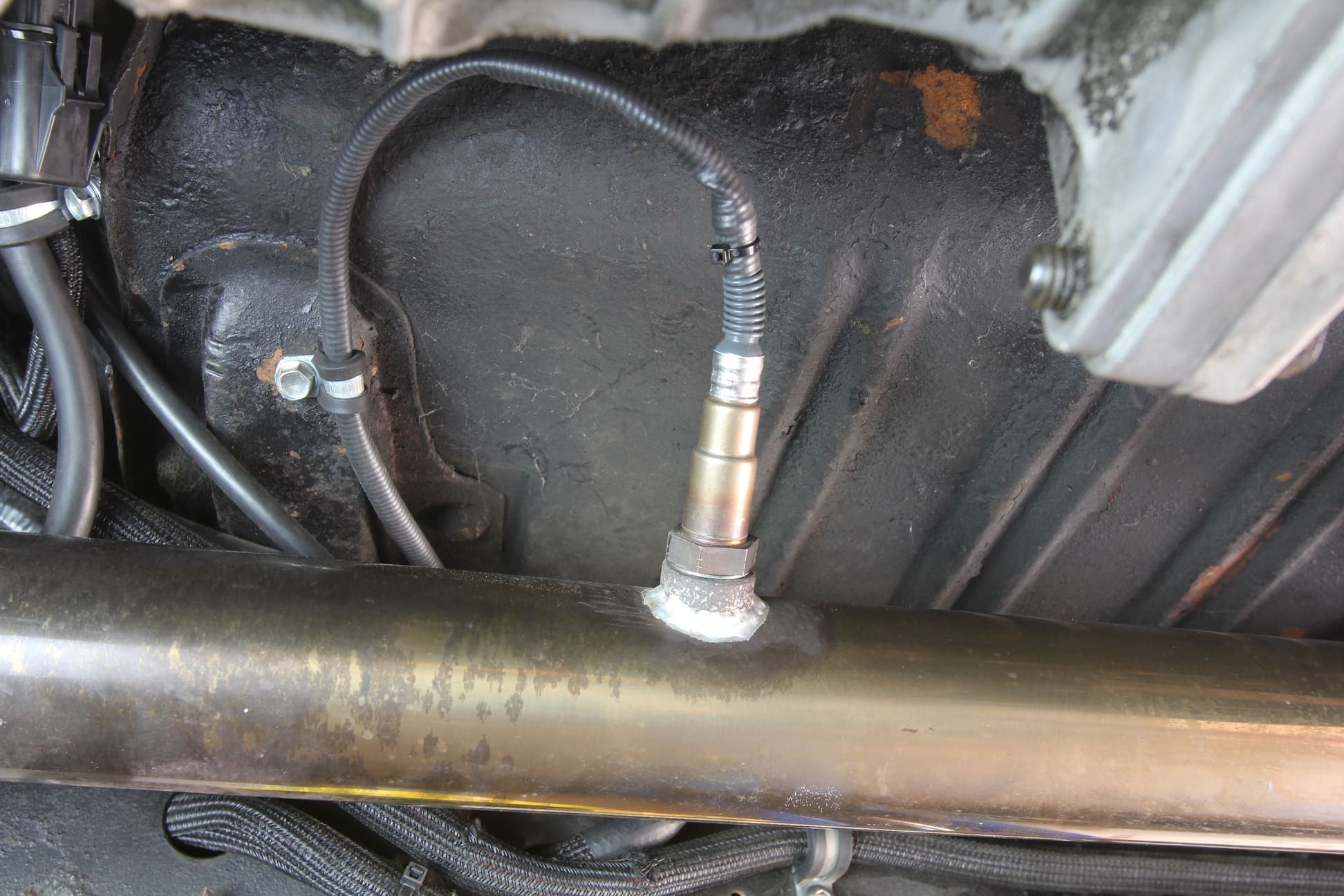
O2 Sensor
Most modern EFI systems use wideband O2 sensors, either single or a pair, mounted on either side of the exhaust. These measure the ratio between oxygen and fuel levels exiting the engine and send this information to the ECU, where it can react quickly and make the appropriate changes to the fueling of the engine.

Crankshaft Position Sensor
The Crankshaft Position Sensor is located on the passenger side, rear of LS engine blocks and sends a signal to the ECU relating to engine rpm and crankshaft angle or position. The Crankshaft Position Sensor is triggered by either a 24x or 58x reluctor wheel mounted on the crankshaft inside the engine block, just visible at the bottom of the photo.

Camshaft Position Sensor
The camshaft position sensor relies on a hall effect sensor and a reluctor wheel mounted on the camshaft to deliver precise camshaft position to the ECU. Many early LS engines and some late truck blocks had the camshaft position sensor mounted at the top rear of the block, near the aforementioned oil pressure port. When GM introduced the 58x crank reluctor to increase the resolution of the previous generation’s 24x, they moved the camshaft position sensor to the front of the block and increased it to what’s known as a 4x trigger.
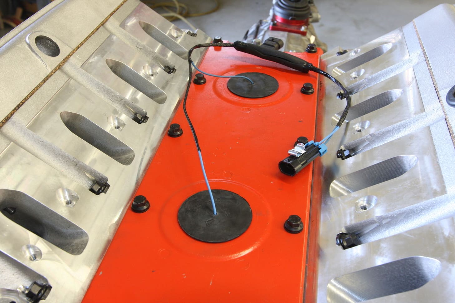
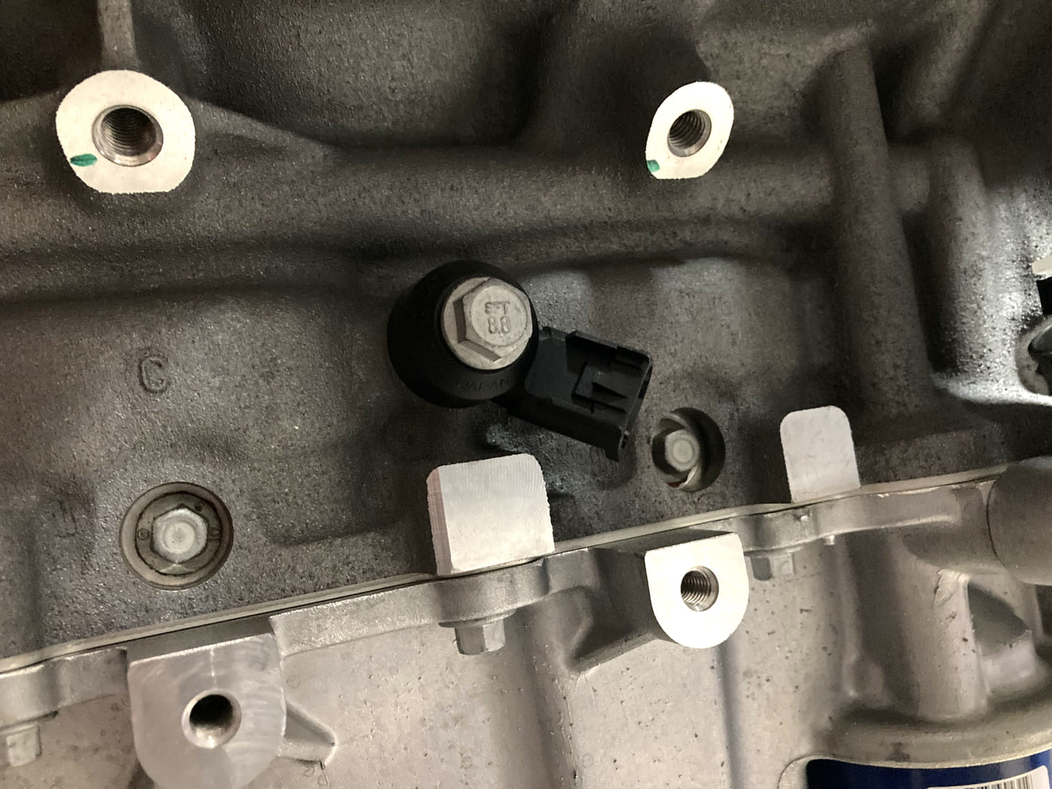
Knock Sensor
A knock sensor detects sounds and vibrations inside the engine block and sends that information to the ECU where it is processed and determined to be detrimental or not. Using the information gleaned from a knock sensor allows the ECU to detect issues such as detonation and react responsively (retard timing and so on), preventing potential engine damage. These are common on modern engines, such as the LS and LT line, and can be found mounted in the valley cover under the intake manifold or on each side of the engine block (LS3, for example).
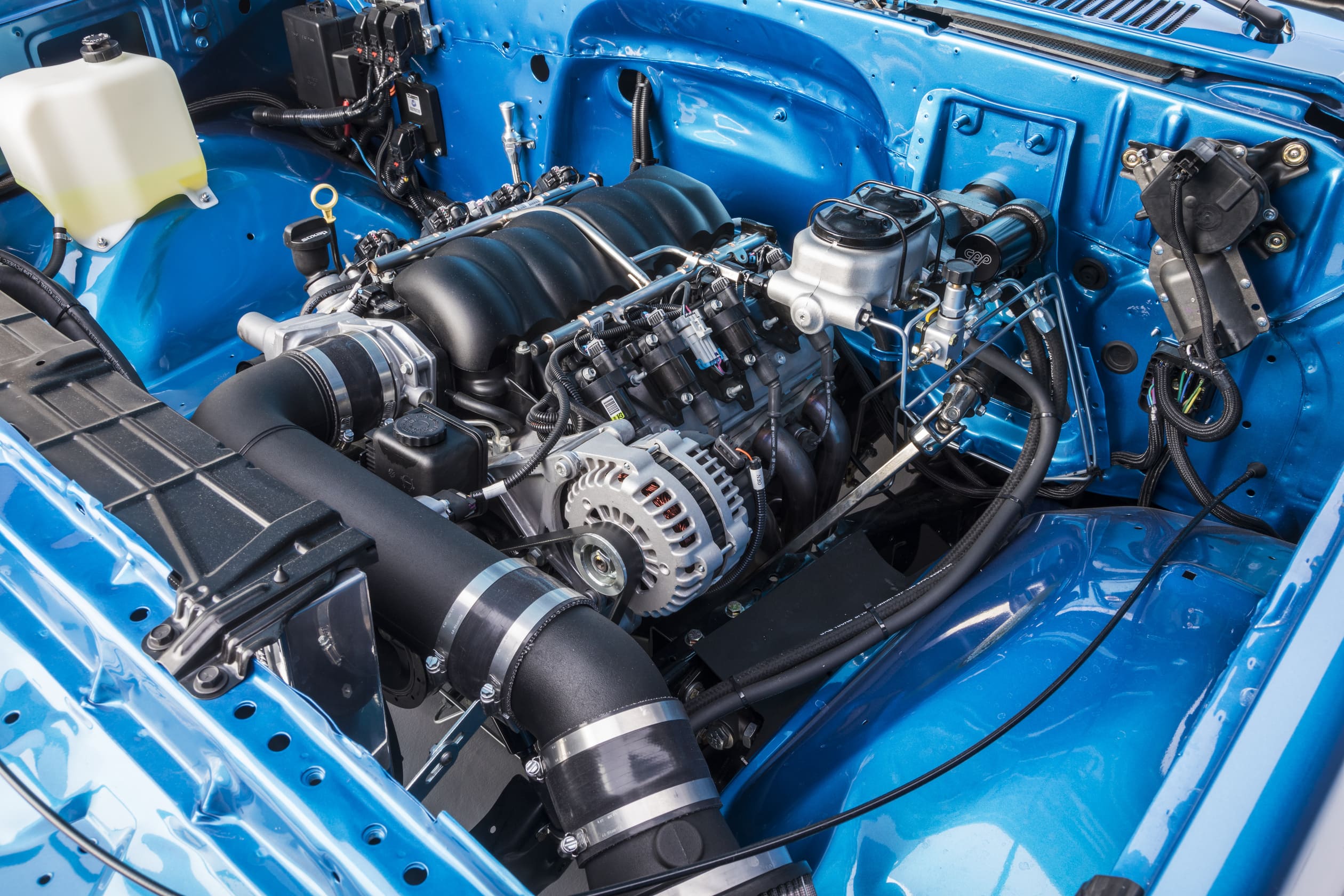
This LS3 swap features a drive-by-wire throttle body that has an internal TPS as well as an electronically driven butterfly valve controlled by the ECU. Directly behind the throttle body is the MAP sensor and mounted in front of the throttle body, along the straight portion of the inlet tract, is the MAF sensor.
Sources
Chevrolet Performance
chevrolet.com/performance-parts
Clampdown Competition
clampdowncomp.com
Holley Performance Products
(866) 464-6553
holley.com