Last month we made the case that classic trucks are about the best project vehicles you can get, they just need a little help in the handling department. To solve that, we installed a complete bolt-on Independent Front Suspension system from Scott’s Hot Rods ’N Customs on our 1964 Chevy C10. It gave us rack-and-pinion steering, adjustable coilovers, and a more modern suspension geometry. So now we’re set up with a front suspension that can handle the twisties and ride like a dream, but what happens when the light turns red? This month it’s all about the brakes.
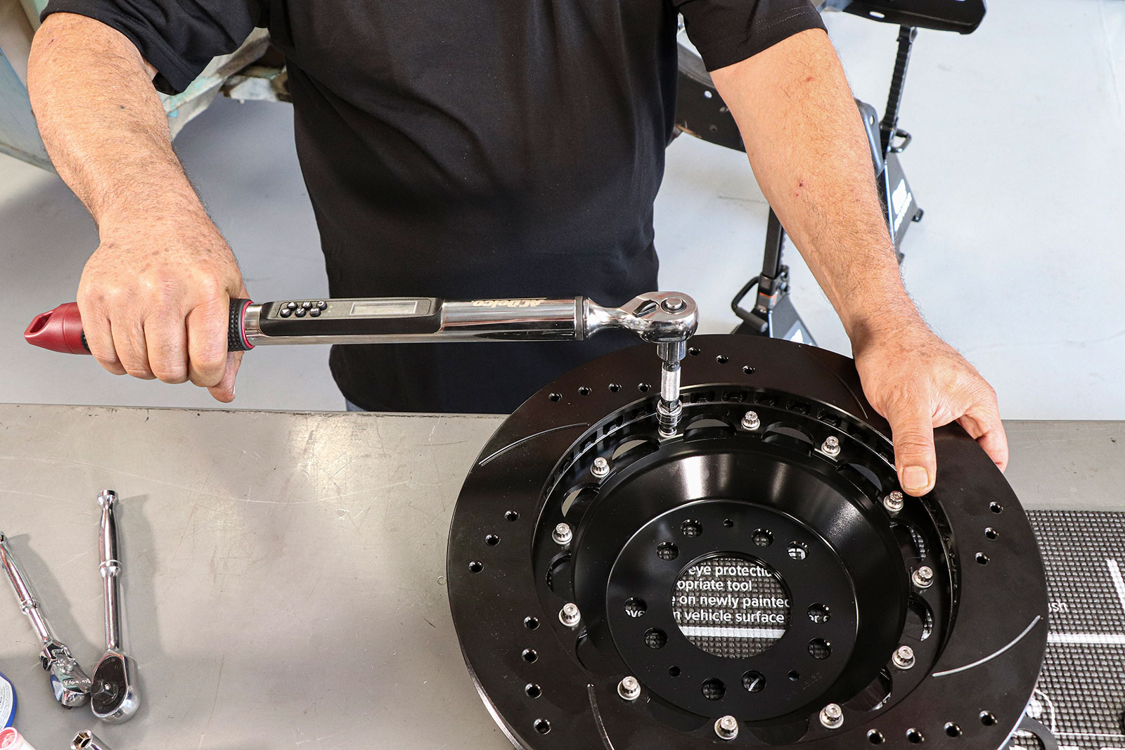
For the most part, the brake install is pretty straightforward. The only thing worthy of a deeper look is assembling the two-piece rotor and aluminum hat. Bolting the two parts together and securing the hardware with safety wire is an important step that we don’t want to overlook, so we’ll get into that in detail below.
Although our 1964 Chevy C10 is substantially lighter than its modern 1/2-ton counterparts, it’s still a truck. Plus, once we drop in a powerful LS, we’ll have some serious power to lasso, too. To make sure we have more than enough brakes to handle an increased payload—or, more likely, increased pace—we ordered our Scott’s Independent Front Suspension system with a stout Wilwood brake kit.
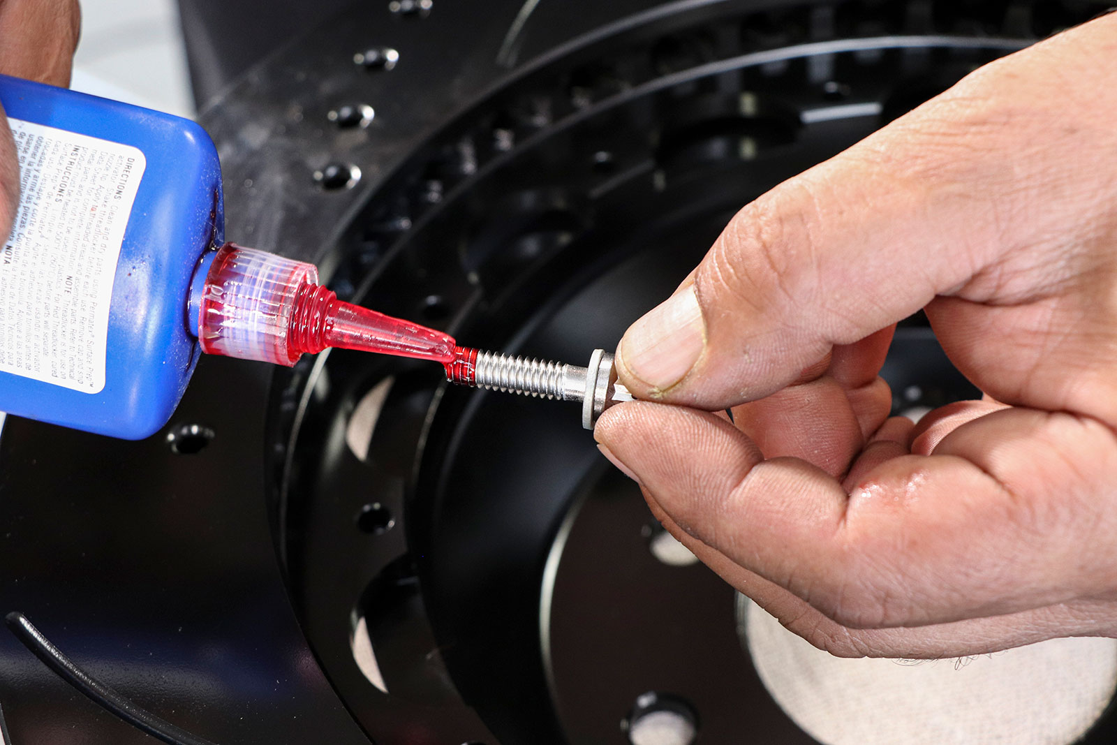
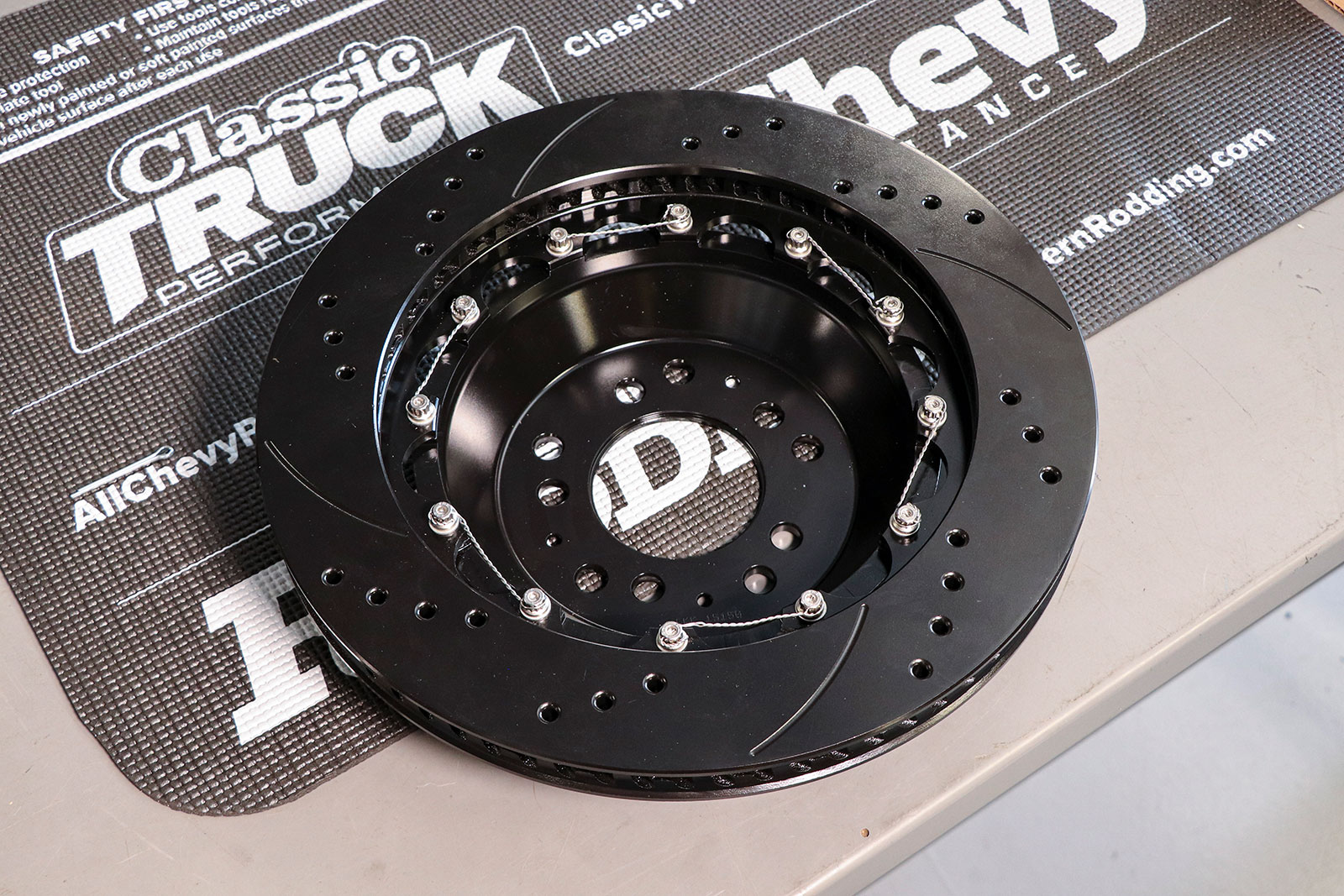
We started by installing the 14-inch rotor to the aluminum hat using the supplied hardware. Make sure to use a high-temp thread locker on all the bolts and torque to just 180 in-lb.
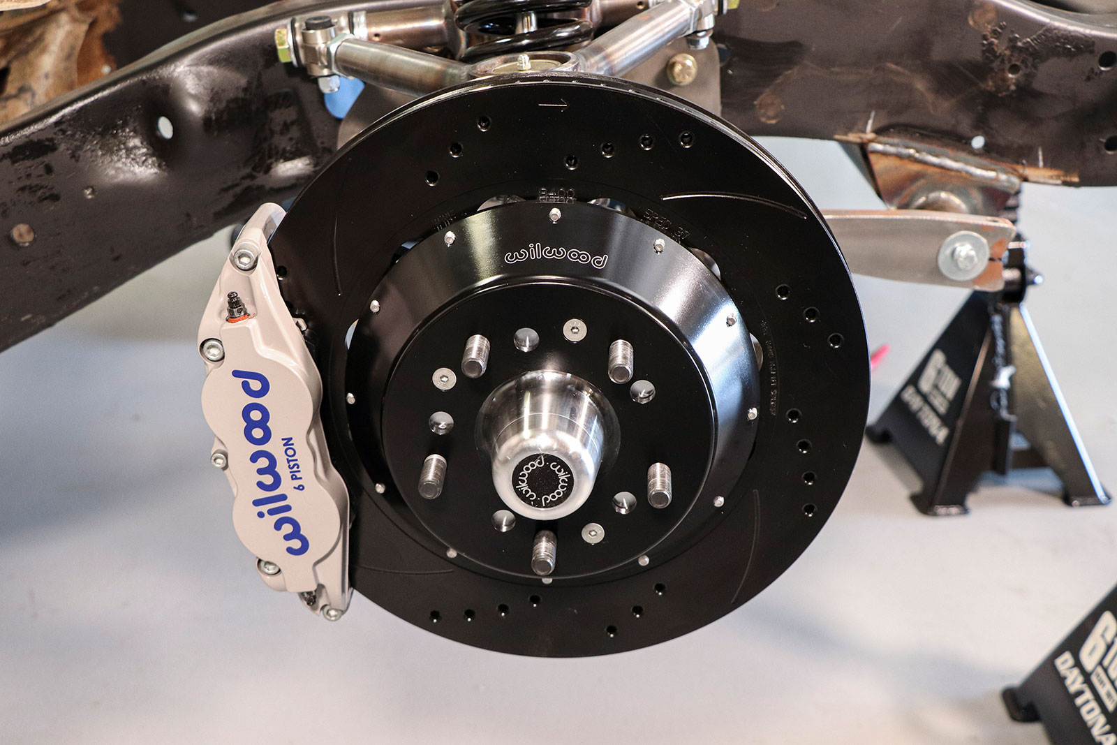
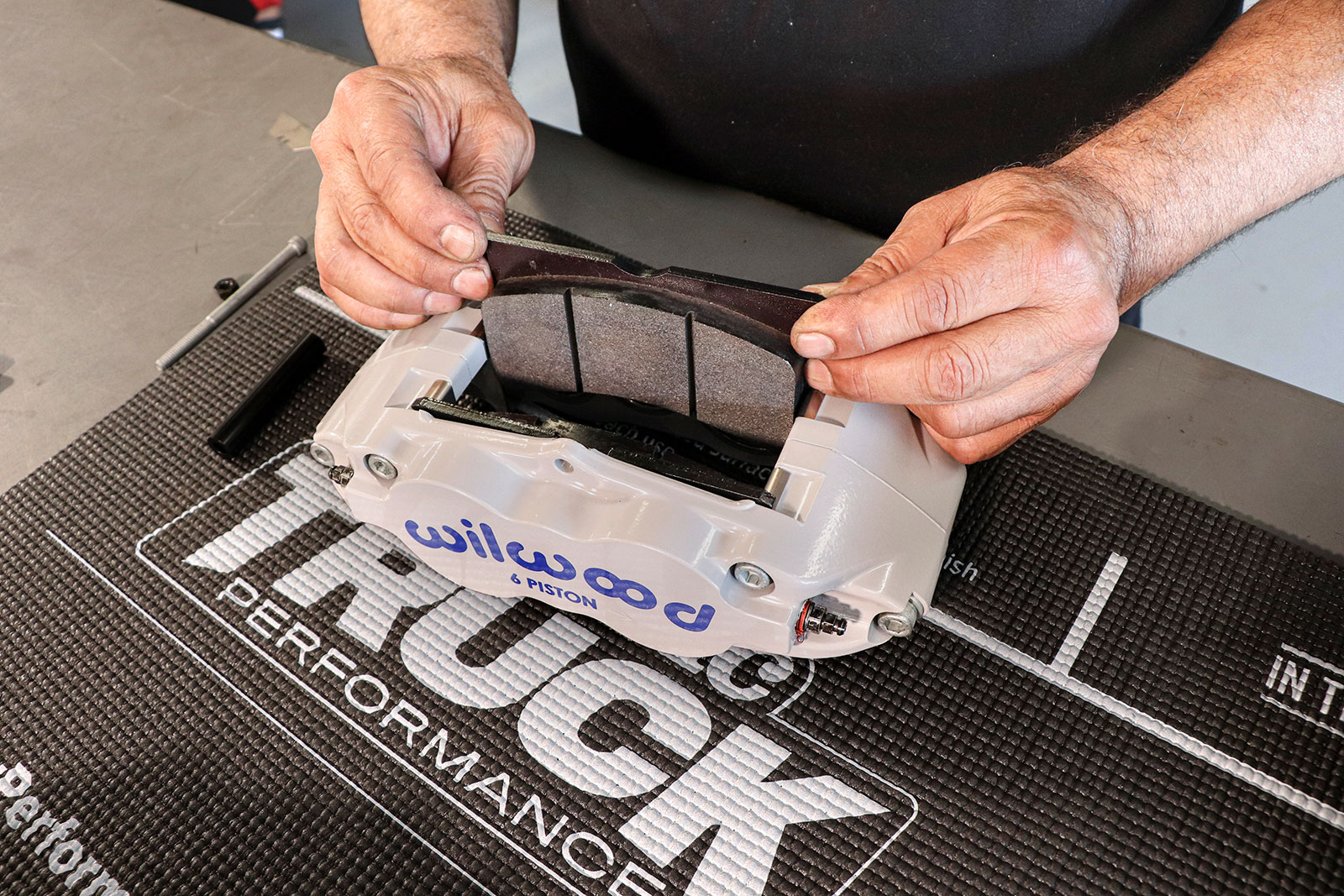
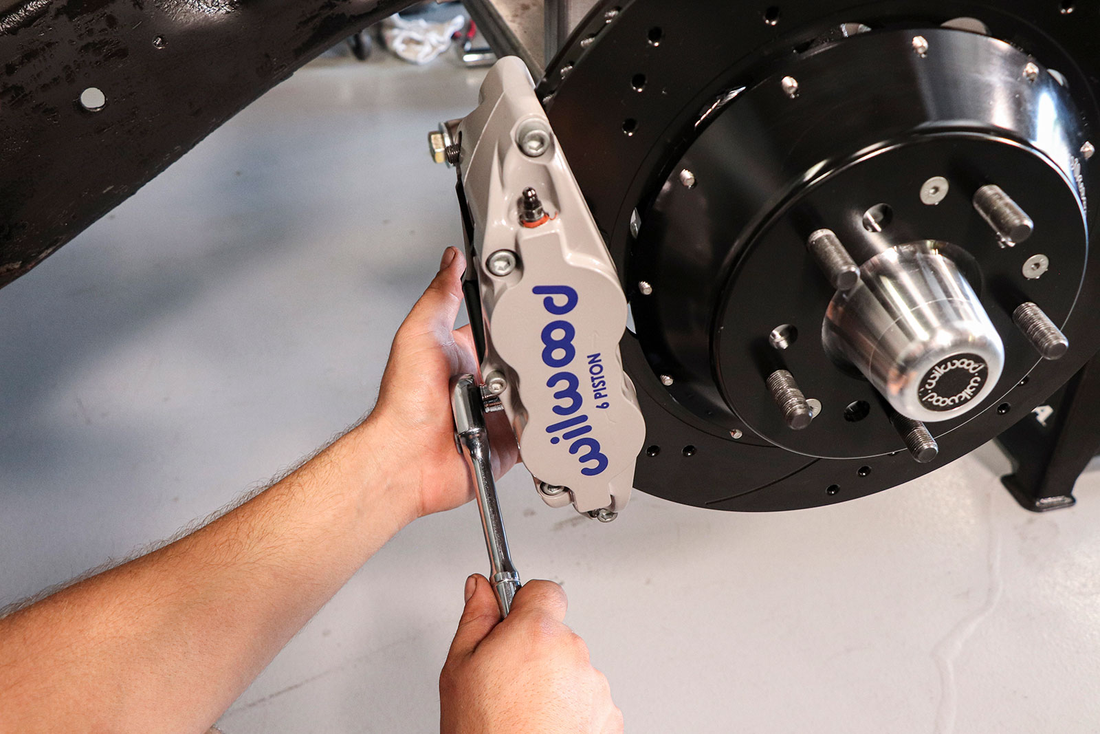
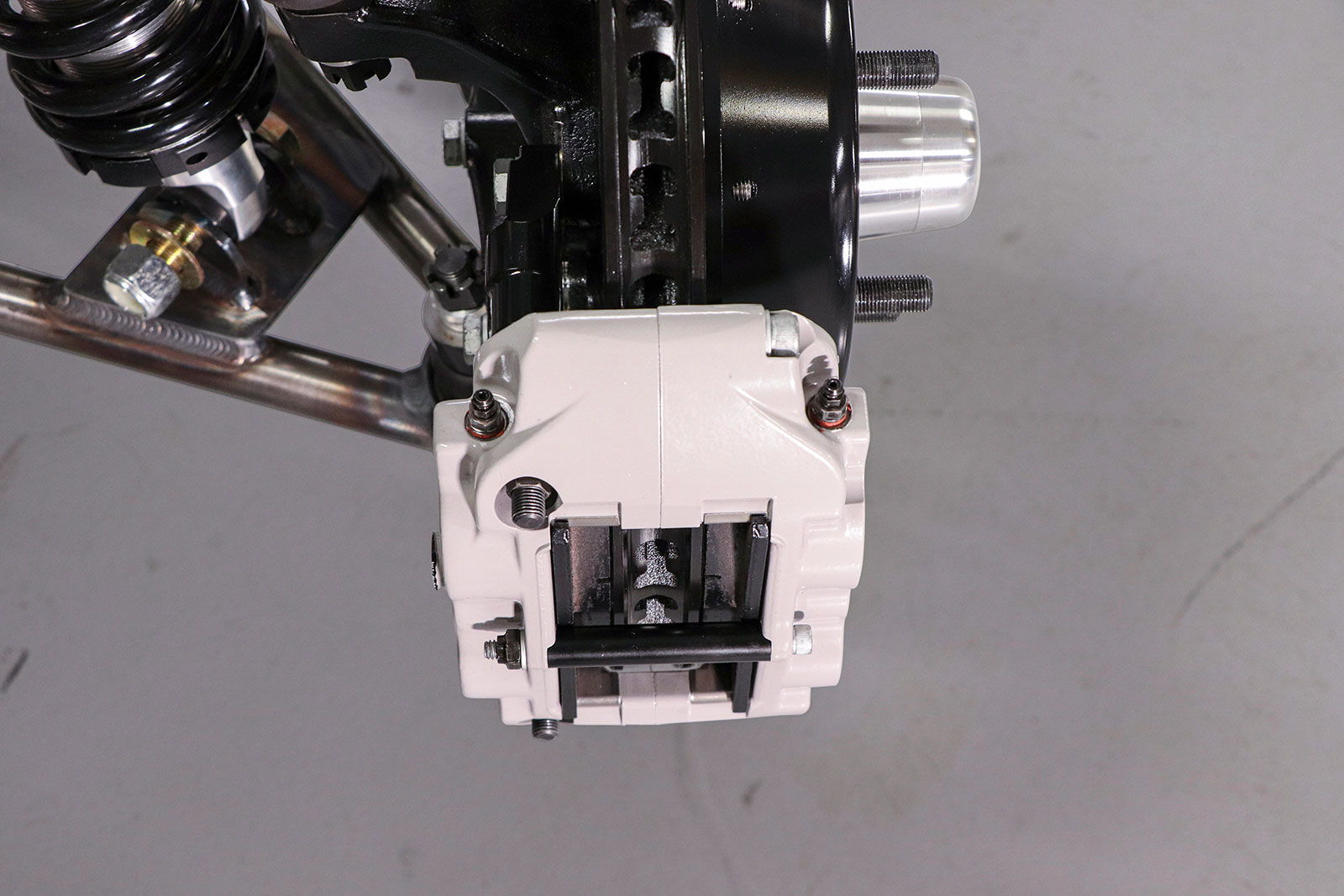
The combination we went for included six-piston forged aluminum calipers clamping down on a set of two-piece, 14-inch, drilled-and-slotted brake rotors. It all mounts up to Wilwood ProSpindles with aluminum hubs that add up to a strong yet lightweight package. These brakes will be able to rein in all the power we can throw at them. We’re also betting they’ll look pretty sweet behind the spokes of some modern 18- or 20-inch wheels.
Note: When using the Wilwood ProSpindles on different frontend/chassis applications, you need to make sure you use the correct square area calipers, brake pads, and rotors for the customer’s use.
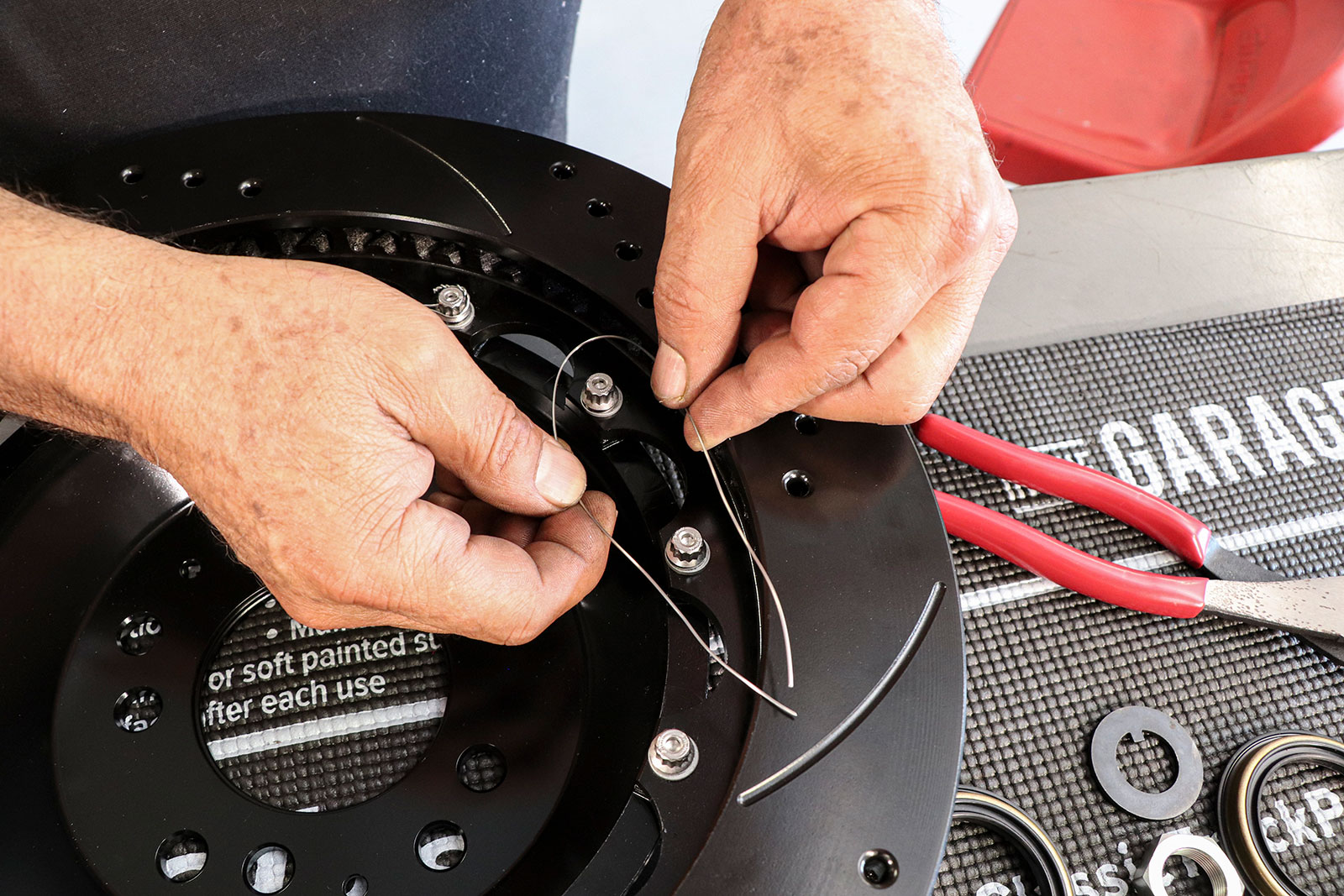
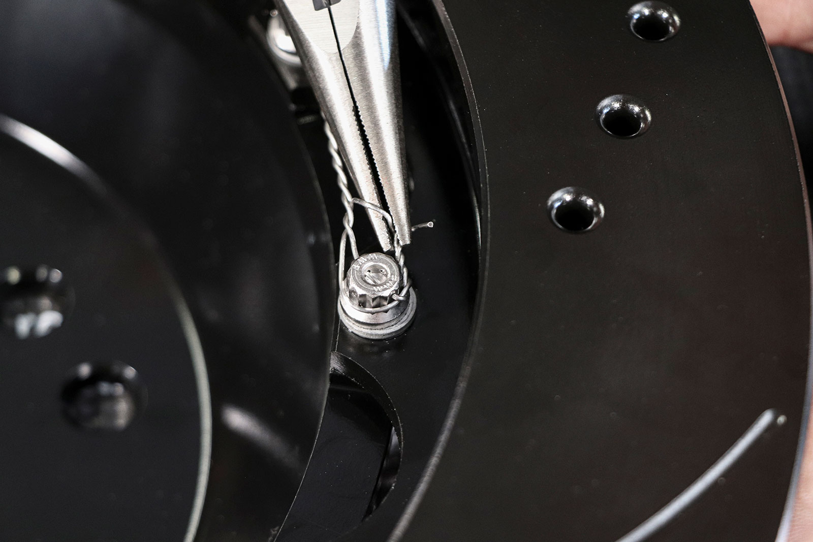
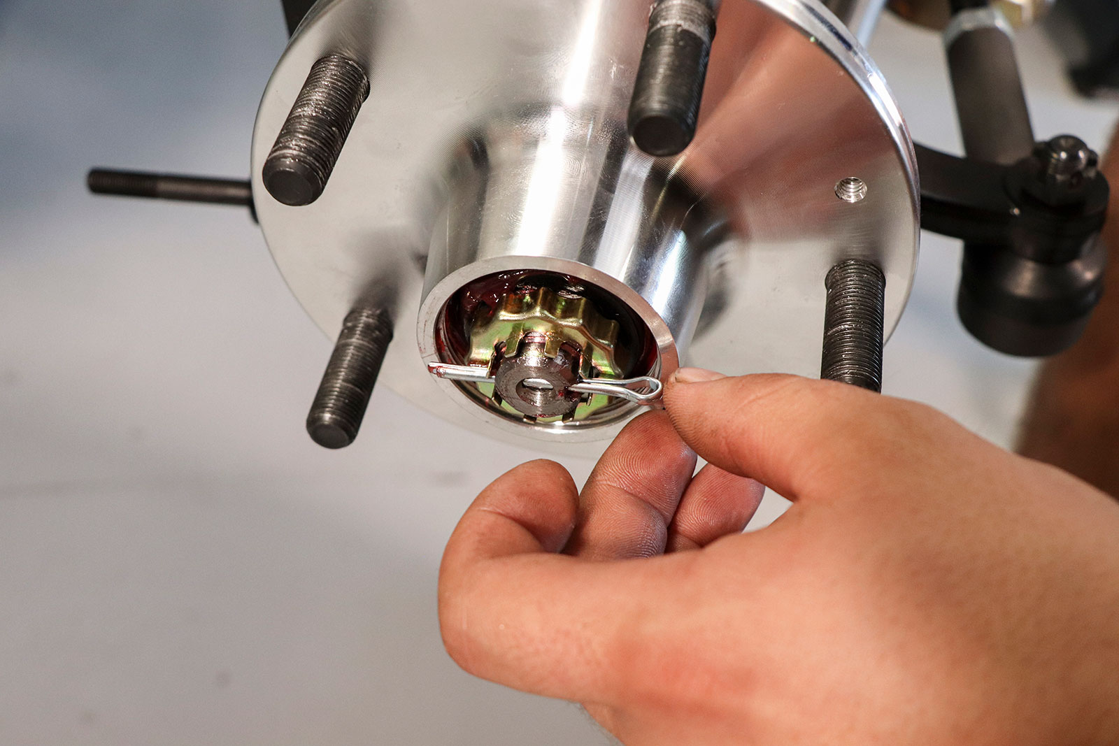
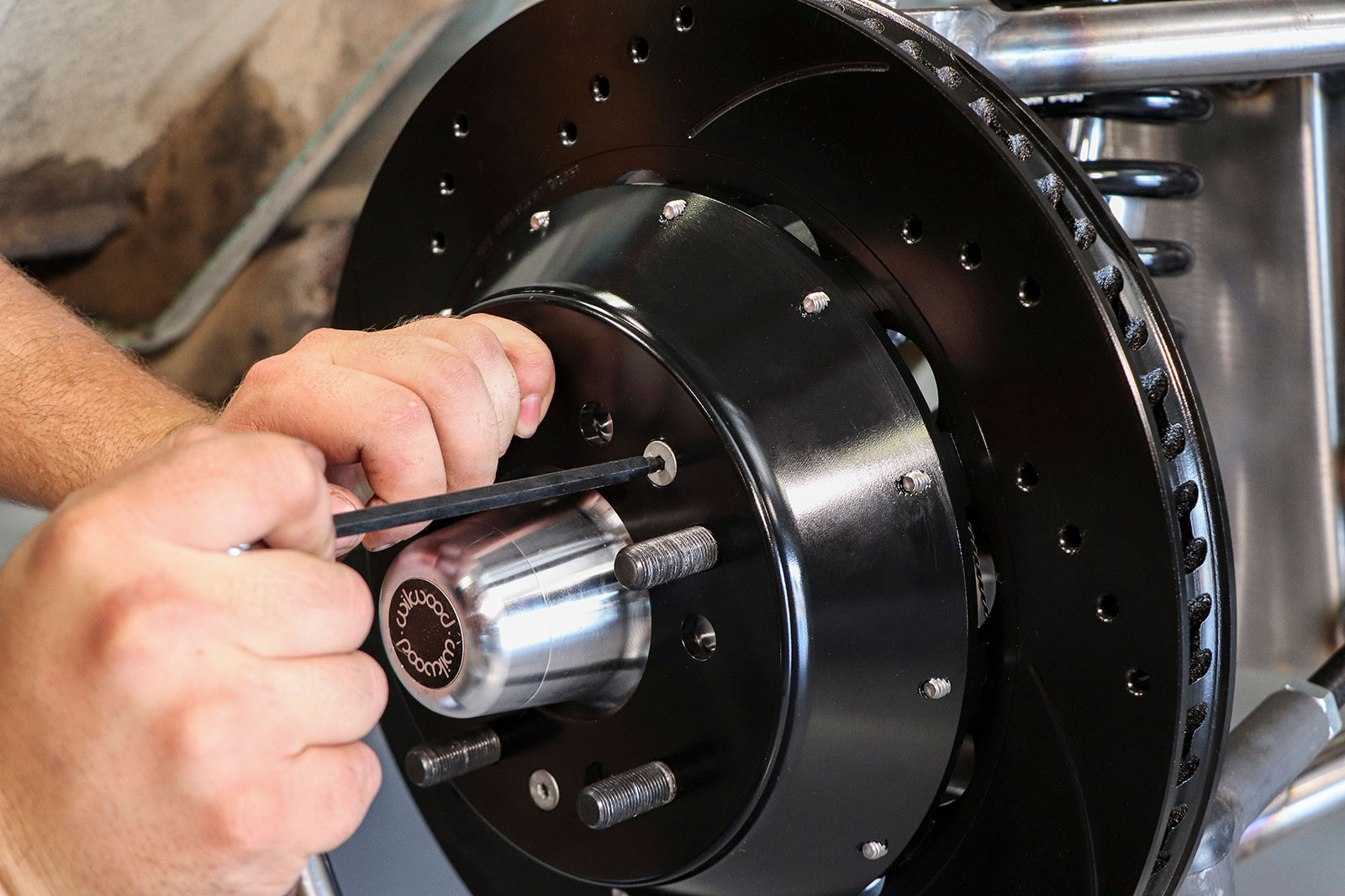
Time for safety wire. If you’ve never done this before just know that it’s OK if it takes a few tries before getting the technique down. Begin by picking two adjacent bolts and cut a piece of safety wire that is about 1-1/2 times longer when folded in half.
For example, if you purchase a frontend using a Wilwood ProSpindle for a ’66 Mustang or ’69 Camaro, the brake kit from Wilwood comes with square area calipers (if it’s a 13-inch or larger brake kit) of 4.06 inches. Great for a street car. But if you purchase a frontend/chassis for a C10 truck, upgrading to either the 4.860-inch Superlite or 5.40-inch Aerolite is in order.
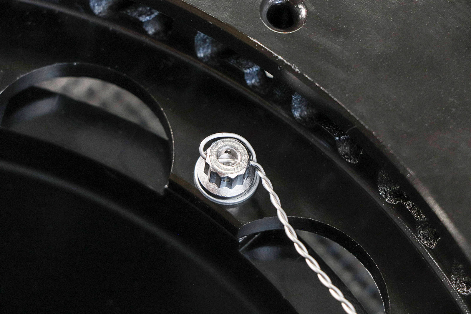
Feed the wire through the small hole in the bolt, bending it around the head clockwise. This ensures the tension from the wire is pulling the bolt tighter. If we ran the wire around counterclockwise the tension would be trying to loosen the bolt.
Why? Because the C10 truck weighs much more than these two street cars, we need the added clamping force of the larger piston calipers to help stop the truck easier and more efficiently.
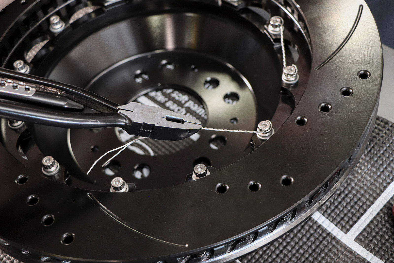
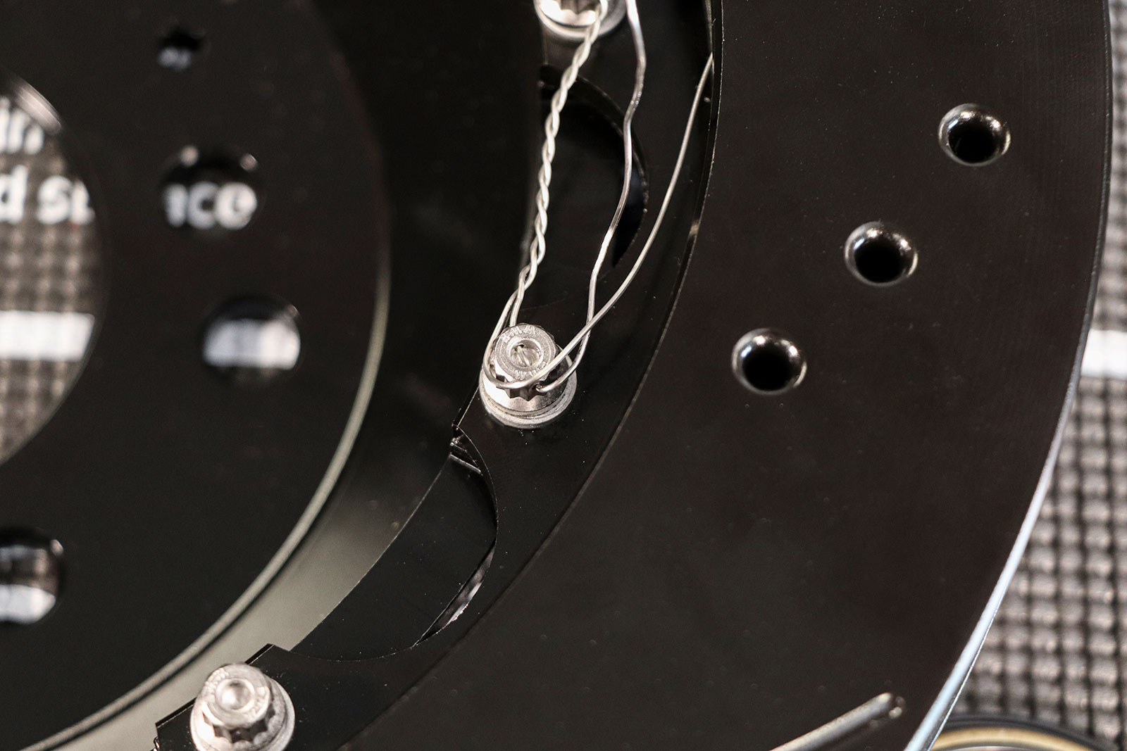
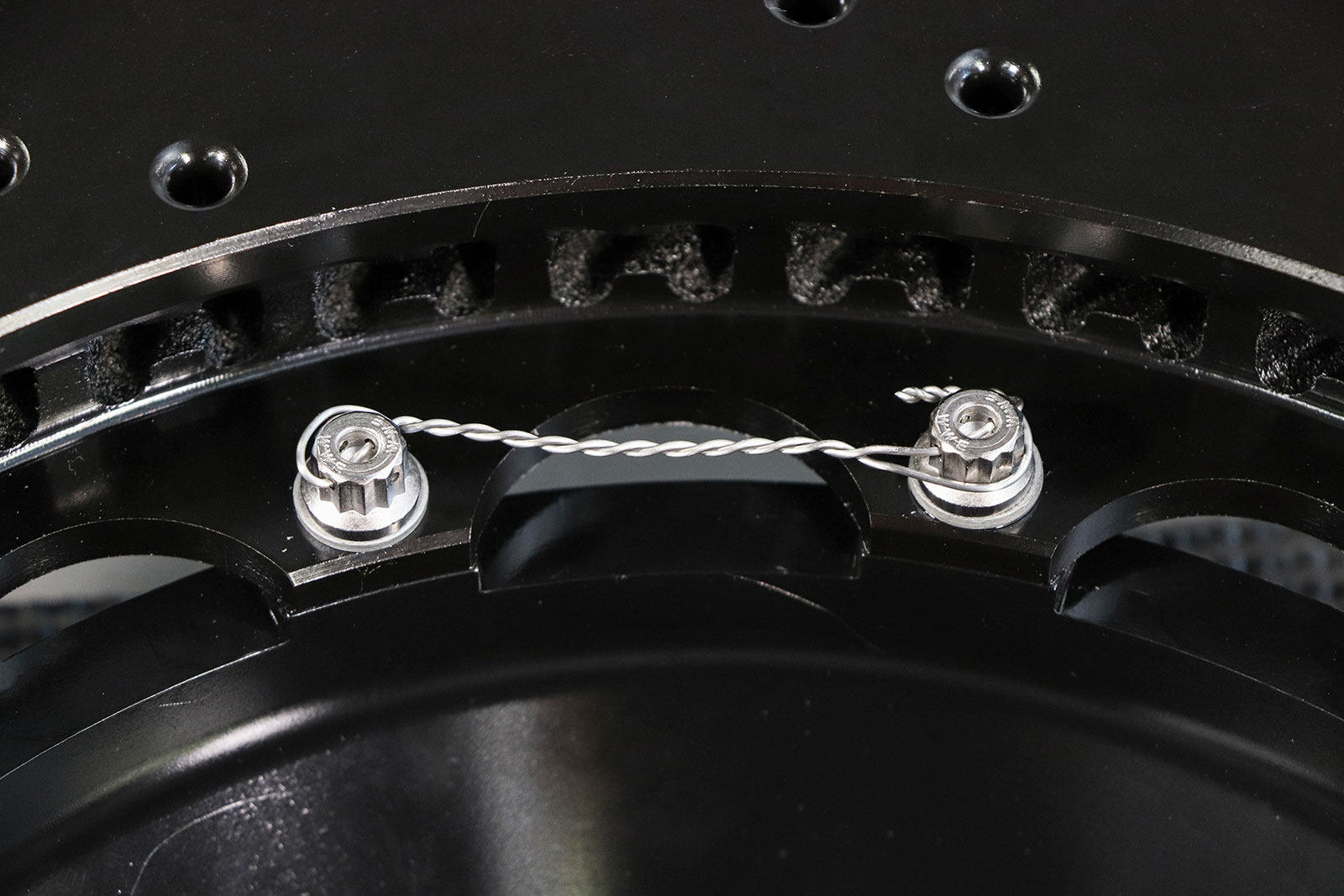
Then use a set of safety wire pliers to twist together the two ends, holding the wires at a distance just shy of the next bolt.Feed one side of the wire through the next bolt and bring the other side around the bolt counterclockwise, again ensuring the tension on the wires is “trying” to tighten the bolt and not loosen it.Finish off the loose ends by twisting them together with a set of needle nose pliers a few times and then clip off the excess.The end result should be a reasonably tight wire that is holding clockwise tension on each bolt, like shown. Proceed to safety wire the rest of the bolts on both rotors in the same fashion.
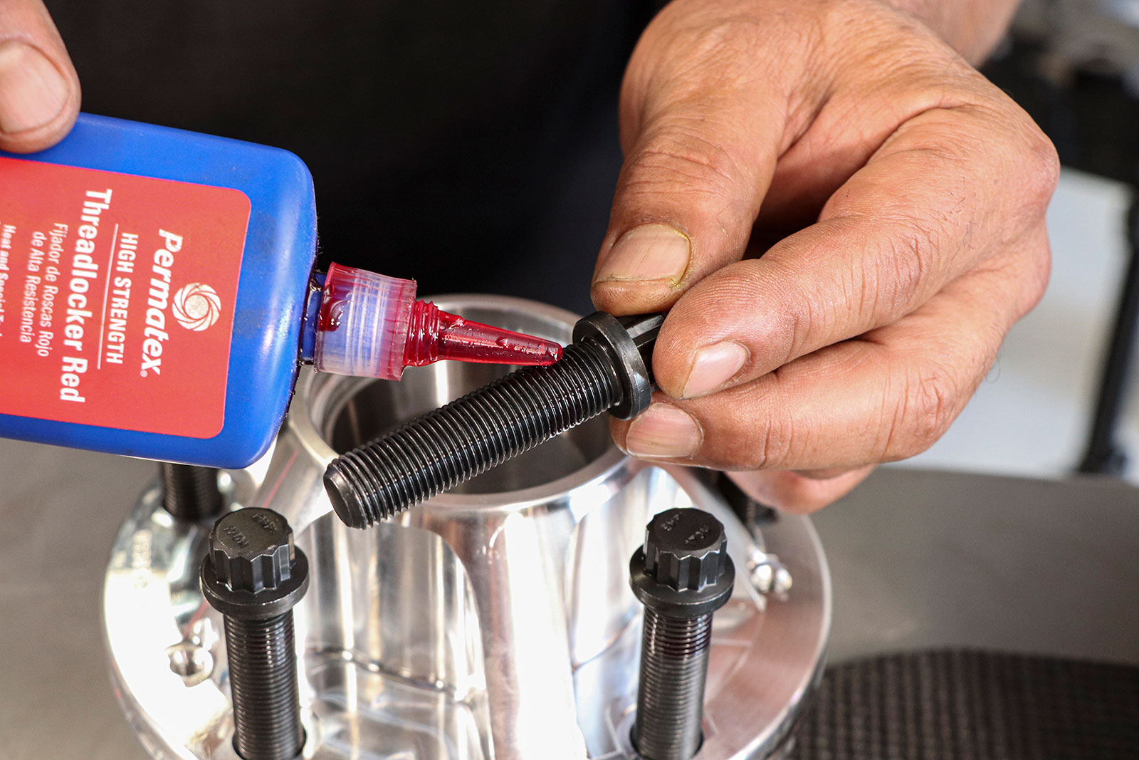
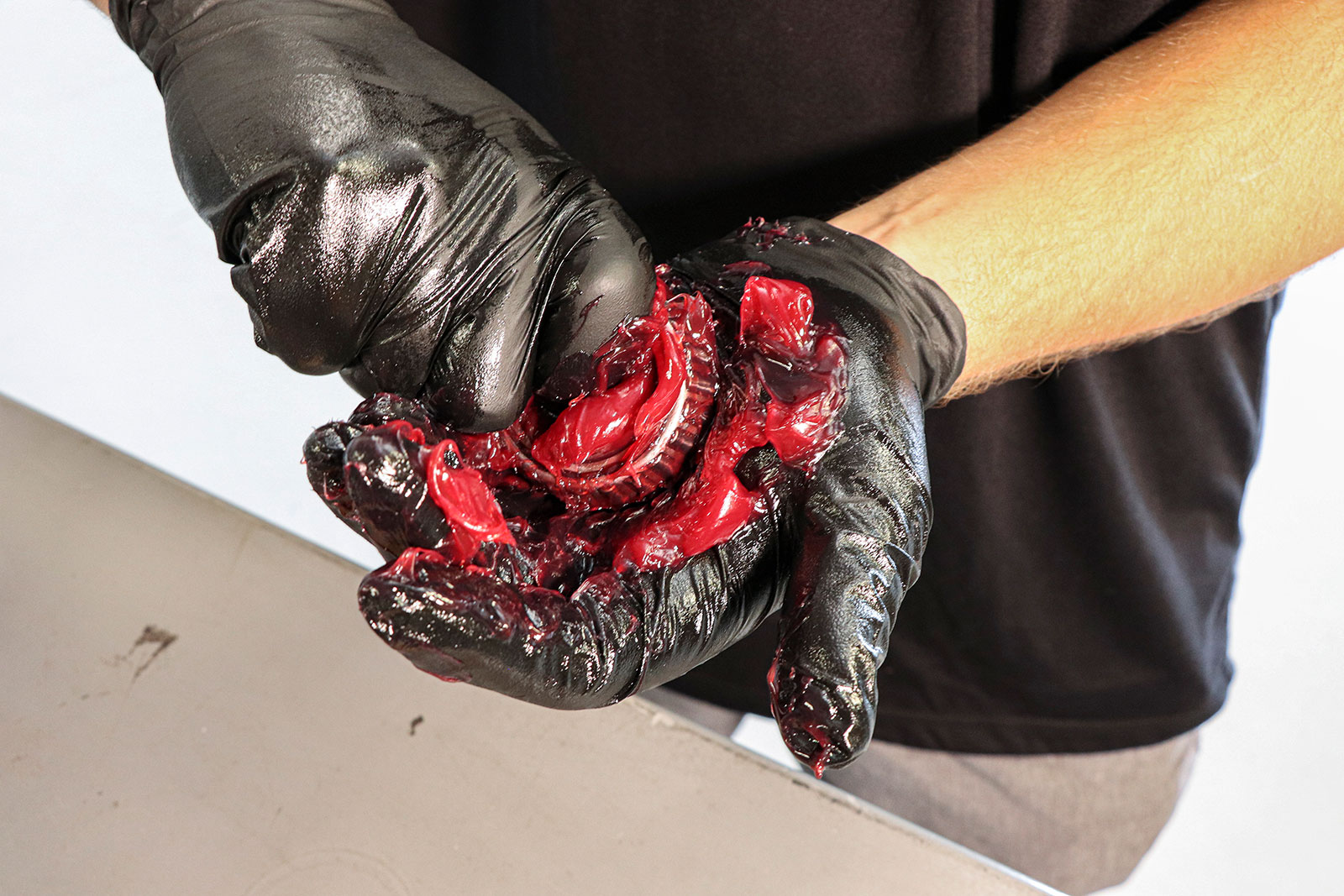
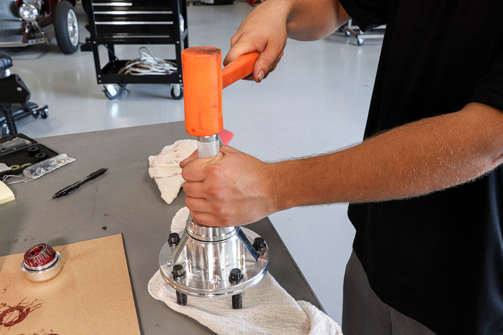
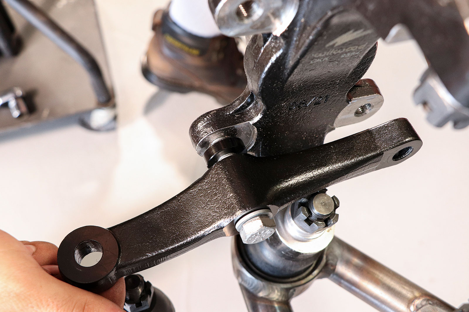
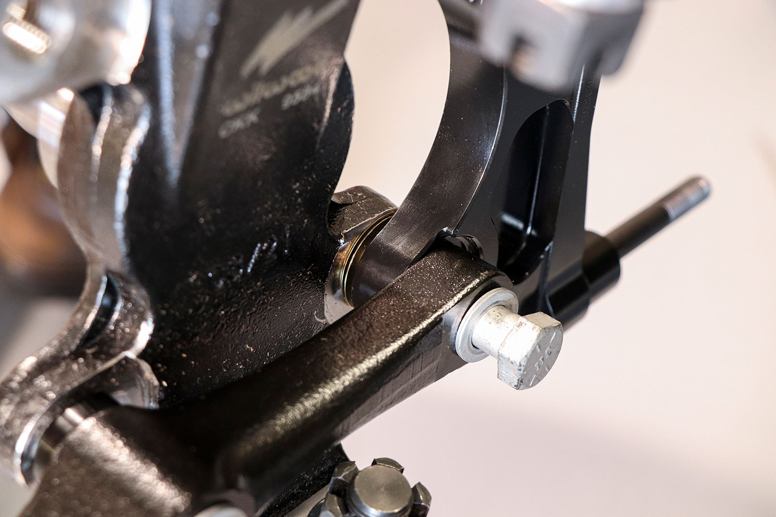
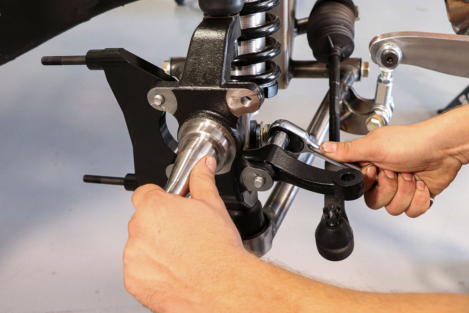
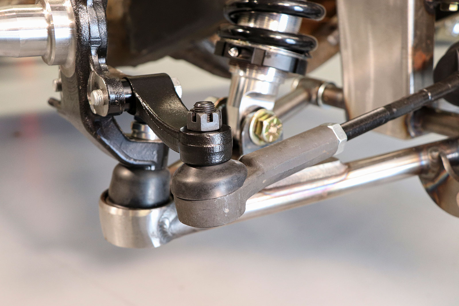
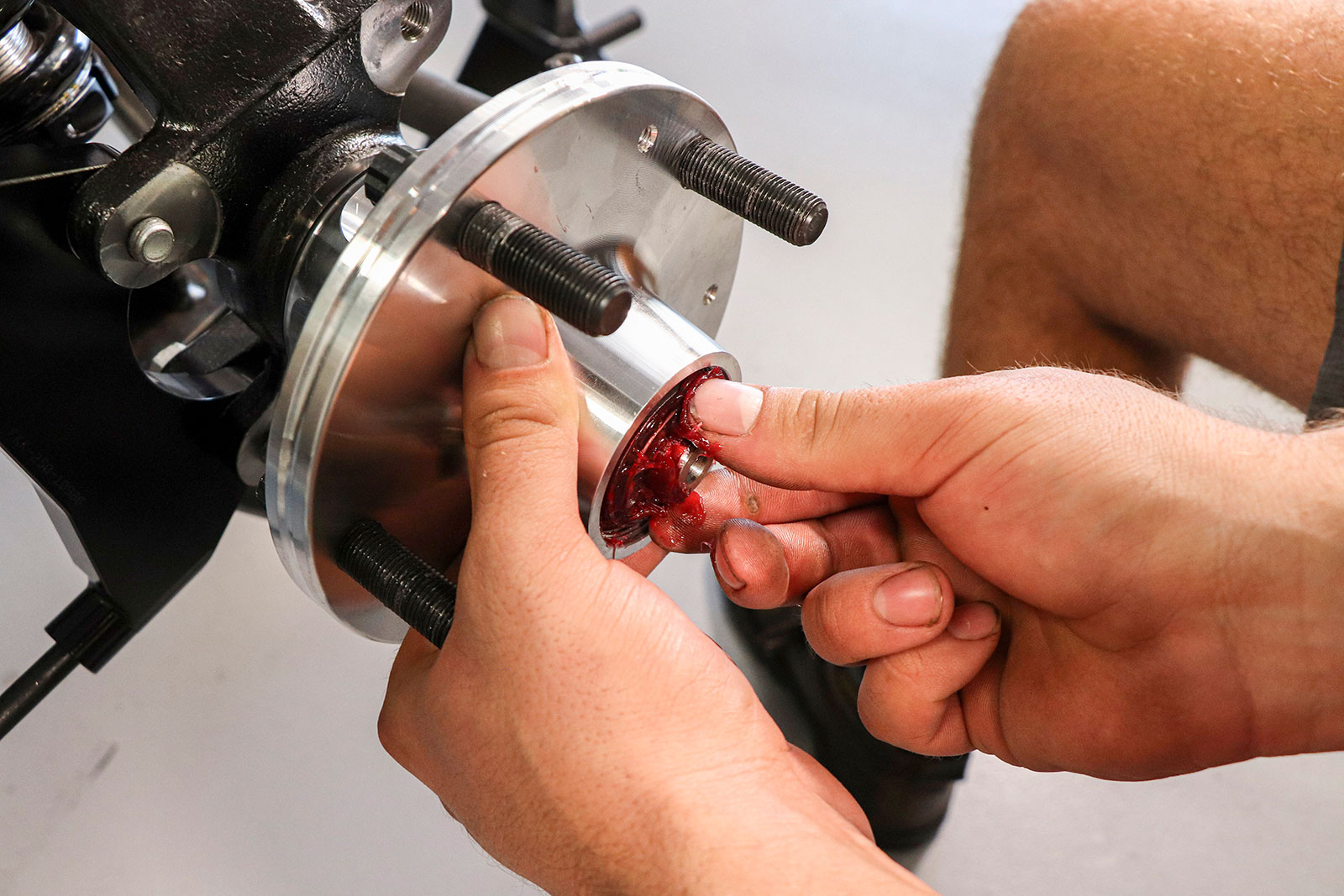
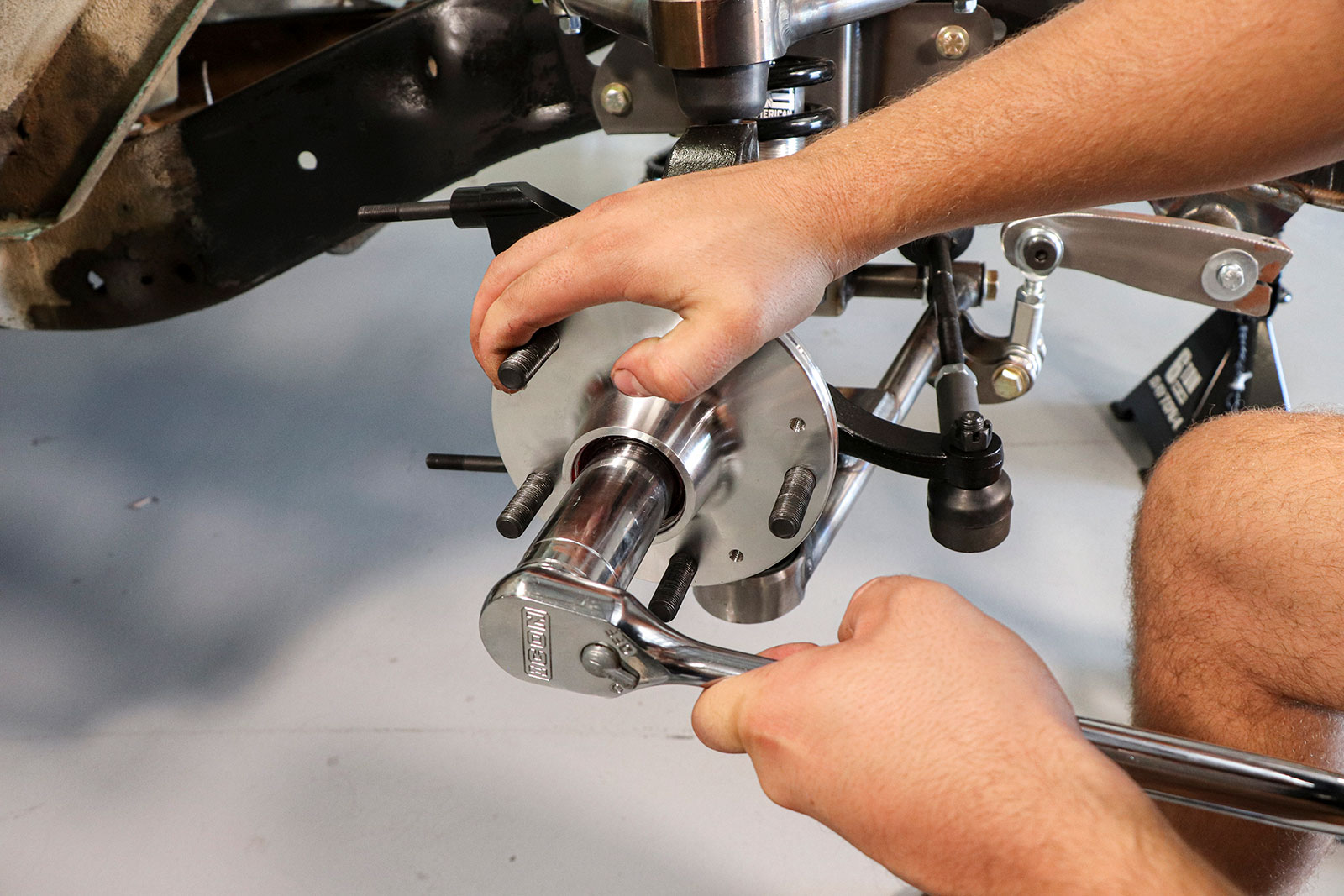
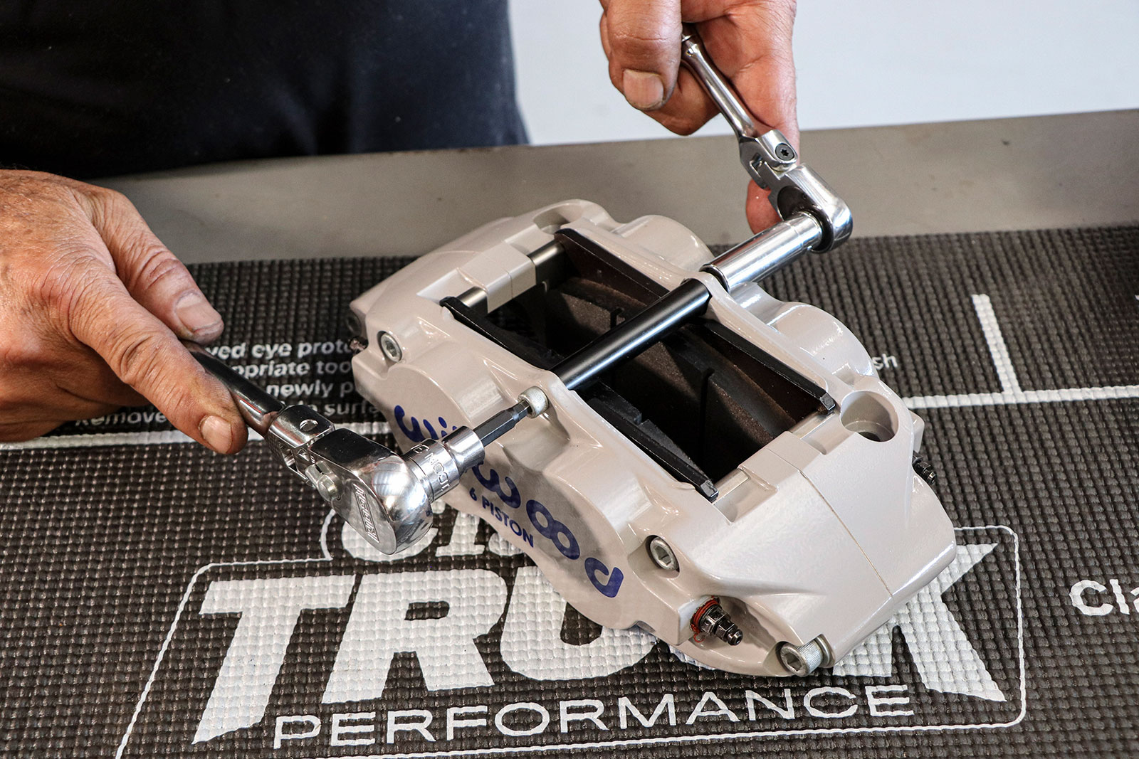
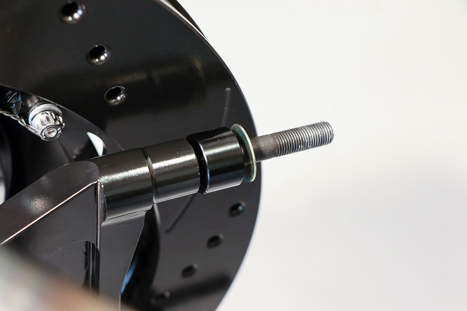
Next we moved onto installing the studs in the aluminum hubs using a high-temp thread locker and torquing to 77 lb-ft.We packed each of the four tapered roller bearings with high-temp bearing grease.After inserting the larger inner bearing into the back of the hub, we installed the seal. A seal installer is best, but a properly sized large socket or block of wood can also be used.Before installing the hub, we attached the steering arm using the provided spacer between the arm and spindle, as shown.Then on went the radial caliper mount with two shims between the mount and the spindle on both the top and bottom bolts.We made sure to use thread locker on the three bolts attaching the caliper mount and steering arm to the spindle and then torqued them all to spec.Next we reattached the tie-rod end to the steering arm. Don’t forget your cotter pins!Then we slid the aluminum hub onto the spindle pin along with the outer wheel bearing we’d greased earlier.After installing the indexed washer and spindle nut, we tightened the nut while rotating the hub until it was fully seated, then backed it off just a bit.The spindle nut is secured using a nut cage and cotter pin before sealing everything up with the dust cap.Next we moved our attention to the pistons, removing the center cross bolt, installing the brake pads, then reinstalling the cross bolt.
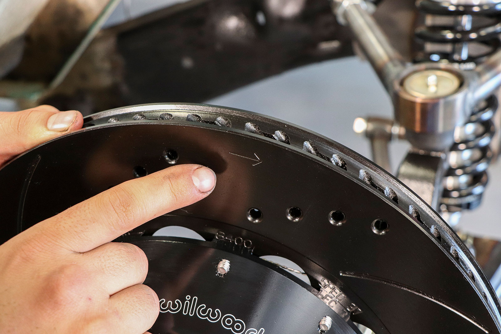
Before installing the rotors, note the arrows etched in the rotor face that show the proper direction of rotation.Three Allen head screws are used to secure the rotor to the aluminum hubs before installing the caliper.One spacer and one washer go on each radial mount pin to properly space out the caliper on the rotor.Torque the caliper bolts to spec and then make sure the caliper is squared on the rotor and that the rotor spins freely.
We use cookies to ensure that we give you the best experience on our website. If you continue to use this site we will assume that you are happy with it.