In a world of twin-turbo LSX engines making upwards of 1,200 hp, we might come across as a bit antiquated—who’s even building small-block Chevys anymore? Scrolling through Instagram and catching up on the latest SEMA builds, you’d be forgiven for forgetting the good ol’ 383ci Chevy. But scroll through your favorite online hot rod parts store like Speedway Motors and you quickly realize the humble small-block is far from dead. With the wide variety of complete rotating assemblies, top-end kits, and engine dress-up kits available on SpeedwayMotors.com, it’s never been easier to build your own stroker engine at home.
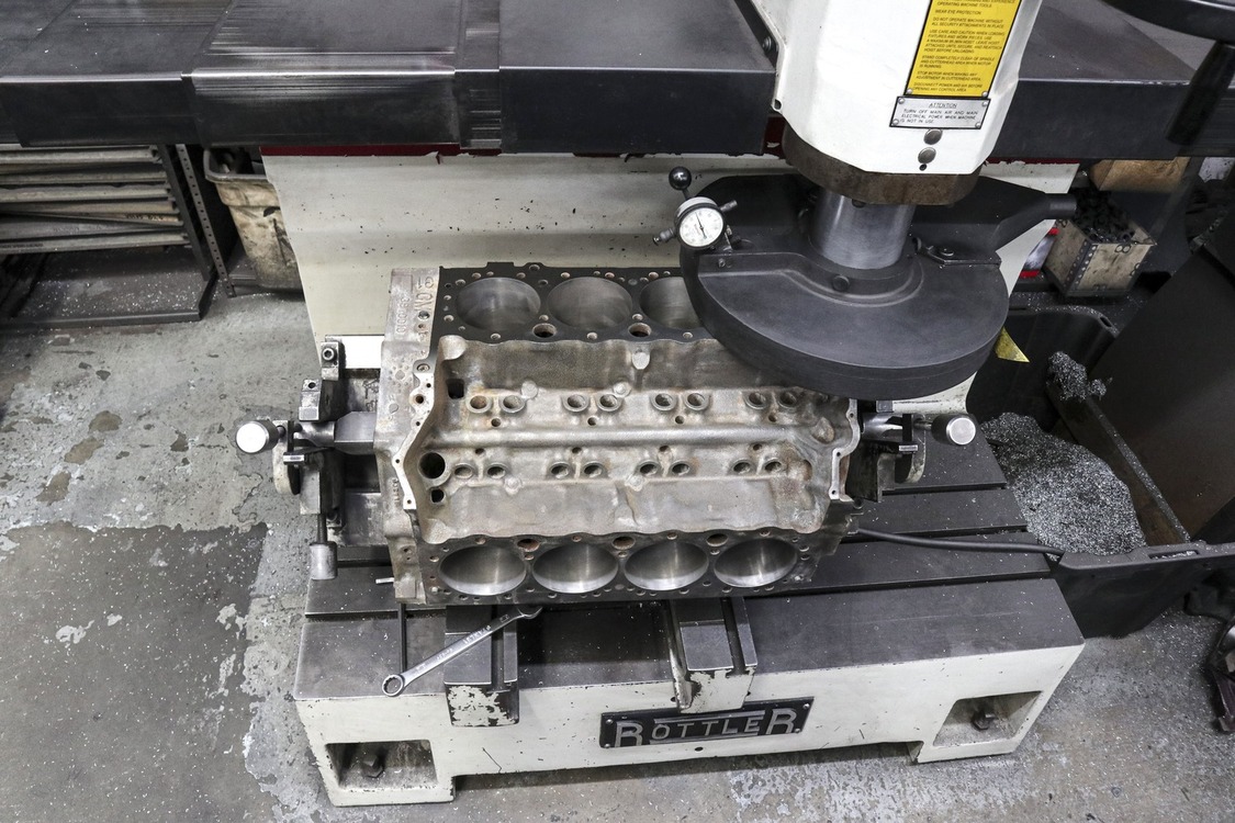
After tearing the engine down to a bare block, they threw it in the hot tank to clean off all the grime. Next, they magnafluxed it to check for cracks before proceeding to the bore and hone.
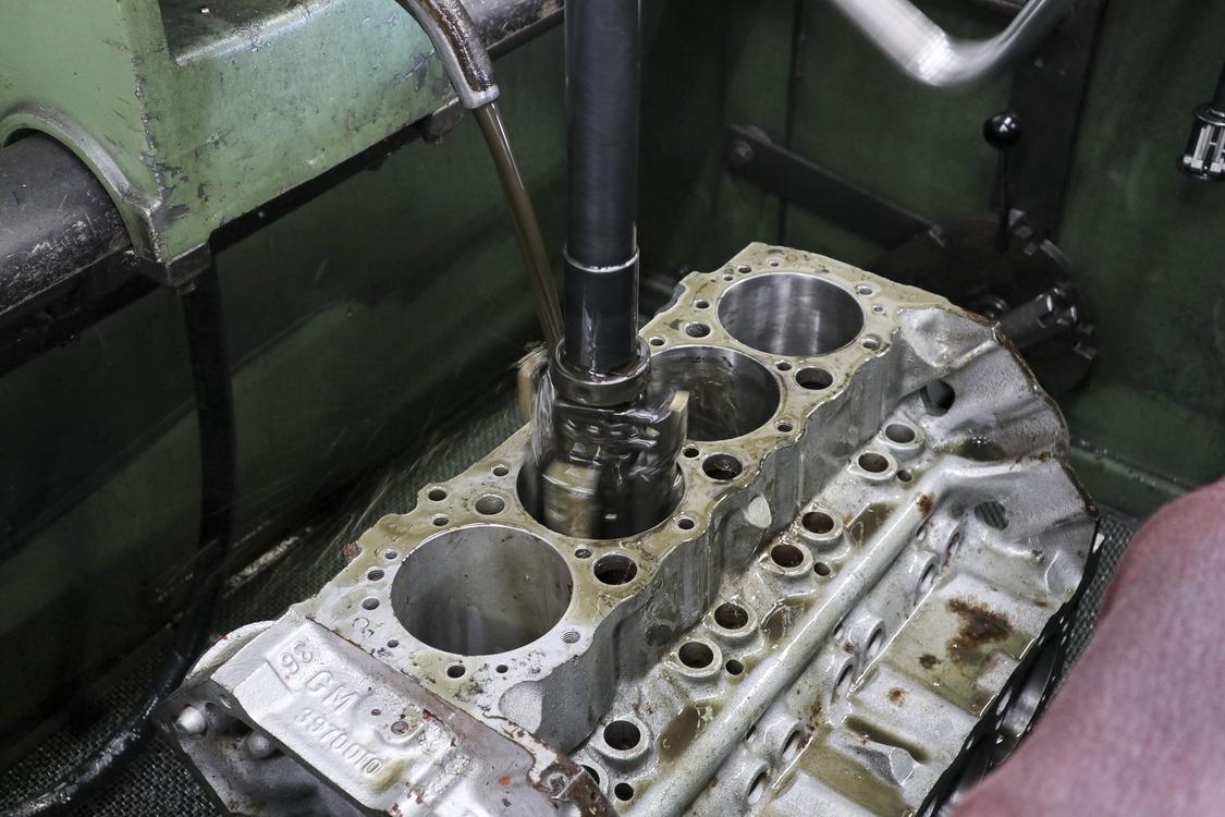
To get the ball rolling, we sourced a used small-block 350 with four-bolt mains that someone was getting rid of on OfferUp for a couple hundred bucks. While we’ve heard that a two-bolt main block is just fine for a mild 400- to 500hp build, we wanted to do some future proofing. Plus, four-bolt main blocks aren’t all that tough to come by. We also got lucky finding a block that had yet to be rebuilt, so we would only have to go 0.030 inch over when boring the cylinders.
The guys at L & R Engine also decked our block—another step that is not technically required but is generally a good idea. This makes sure the top of the block is perfectly square for optimum sealing against the cylinder heads. They even checked to see if our block needed a line hone (it didn’t) and then went so far as to primer and paint it for us.
With the foundation for our build in hand—er, on a stand—we got onto the fun part and start shopping for speed parts. Speedway Motors makes it way too easy with their array of 383 stroker rotating assemblies.
The first decision was whether we wanted a 5.7- or 6.0-inch rod. What’s the difference? The longer 6.0-inch rod offers a less-aggressive angle compared to the shorter 5.7. This means, theoretically, less side load and thus less wear on the cylinder walls. The tradeoff is that the piston needs to be shorter to compensate. That results in the bottom oil ring land needing to be notched to fit the wristpin. This makes some engine builders nervous when it comes to long-term oil control, but we’ve never heard of it causing a real-world issue.
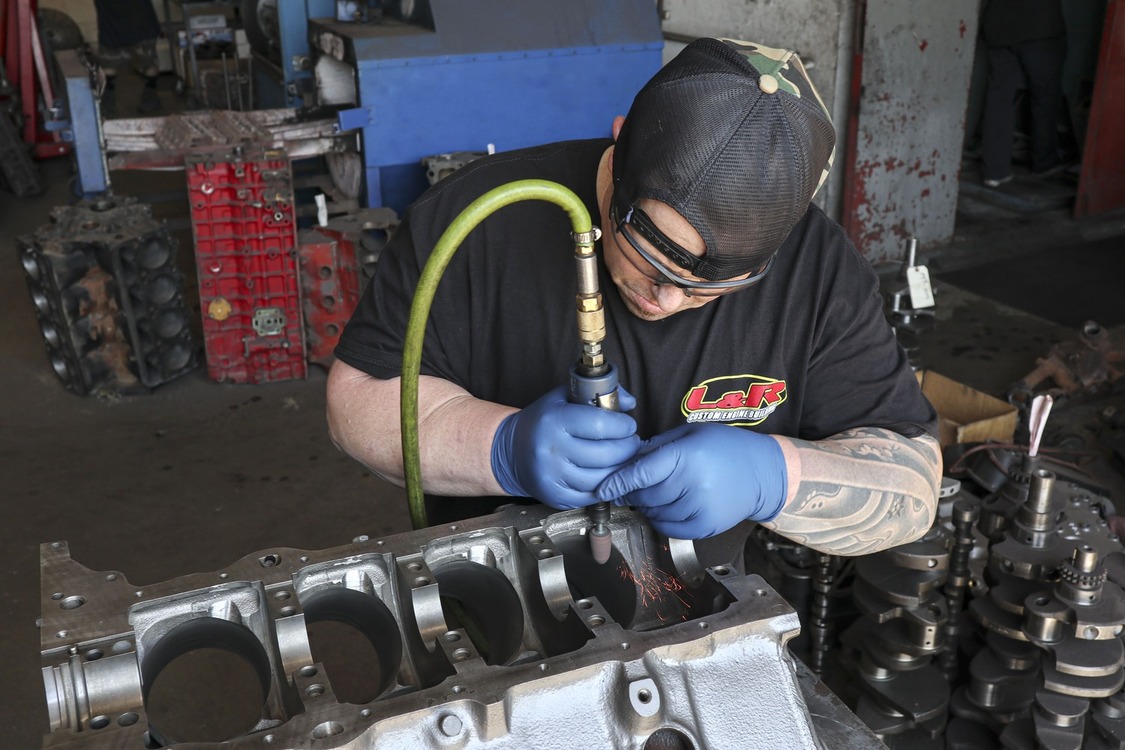
To use a 350 block with increased stroke, the main modification needed is notching the bottom of the cylinders for added rod clearance. More clearance is necessary for use with 6.0-inch rods compared to 5.7 rods and if you take off too much material you can hit a water jacket. Just let your machine shop know what rod you will be using (length and manufacturer) and they should know how much clearance is needed.
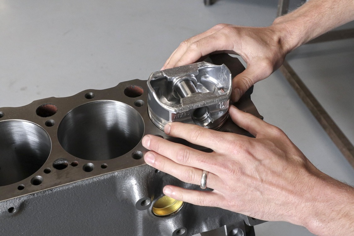
With the pros and cons weighed, we decided on the longer 6.0-inch rods. We also decided the standard kit with a cast crank, forged I-beam rods, and hypereutectic pistons would work well for us. The pistons are a flat-top design with two valve reliefs that when paired with a set of 64cc heads should give us a healthy 10.1 compression. Oh, and another neat service Speedway Motors provides is fully balancing your rotating assembly of choice for a few extra bucks before sending it out. We definitely opted for that one.
Some extra precautions the guys at L & R Engine like to take include deburring the bottom of the cylinders to avoid wearing on the pistons when they rock. They also chase all the head bolt threads and install a test camshaft after fitting the block with new cam bearings.
As for the machine work, we gave some thought to the DIY dingle ball hone and pray method but quickly decided to give our block to a professional. L & R Engine in Santa Fe Springs, California, has a history working with many industry friends, so we gave them a call. Shop Foreman and second-generation engine machinist, Derek Ranney, answered the phone and said they’d be happy to help out.
After a final bath in the hot tank and a good clearing out with compressed air, they installed the expansion plugs and sent us on our way.
We dropped the block off with Derek and his guys at L & R Engine, then caught back up with them later once they’d done most of the requisite cleaning, inspection, and basic machine work. Derek’s son, Derek Jr., would be showing us the ropes and completing the final steps on our block to prep it for its stroked rotating assembly.
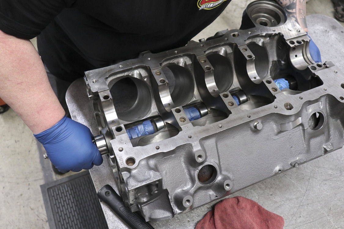
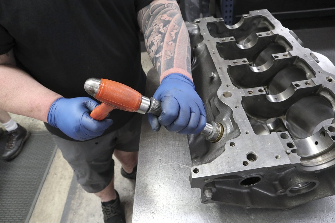
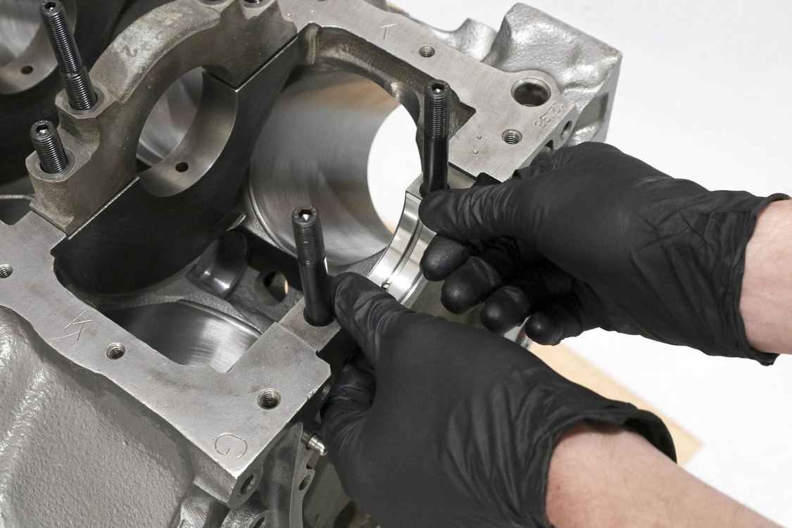
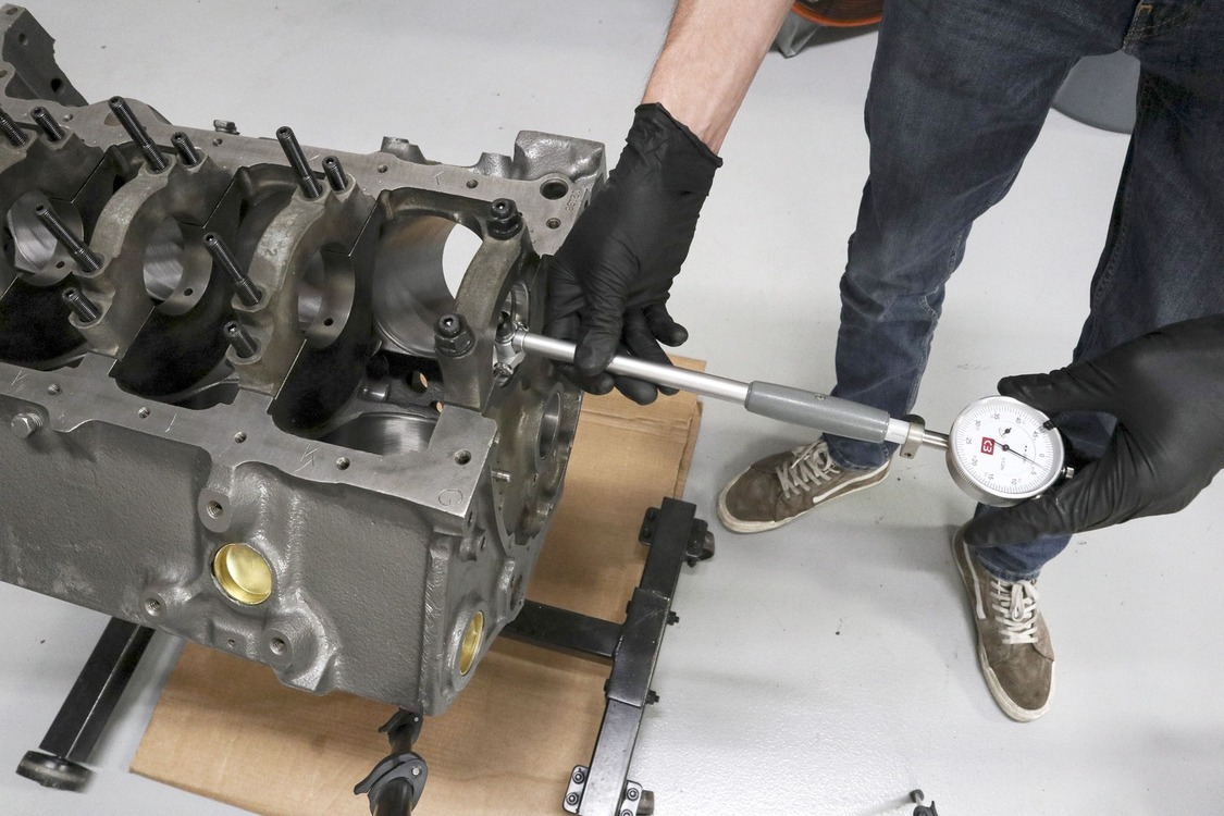
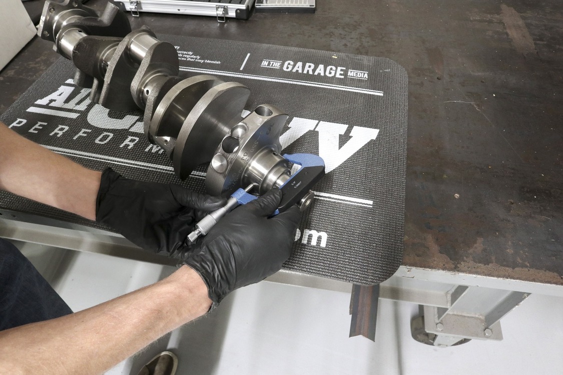
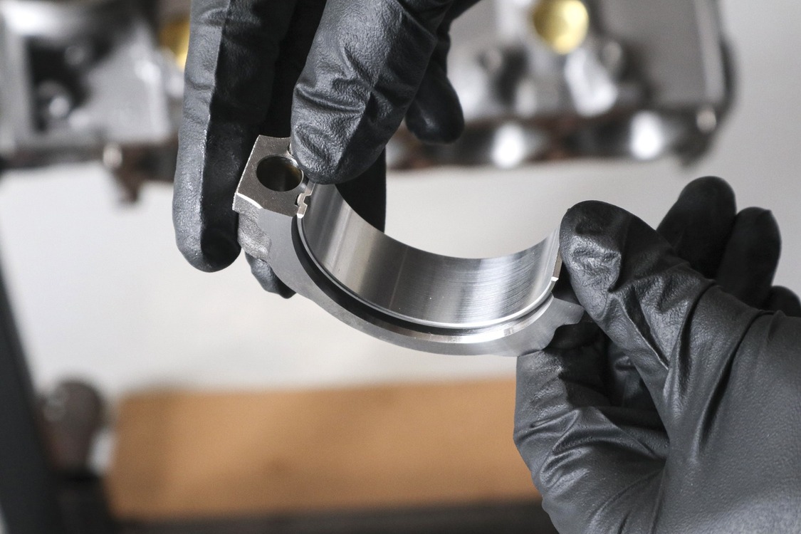
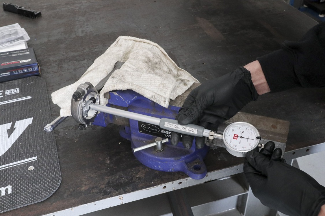
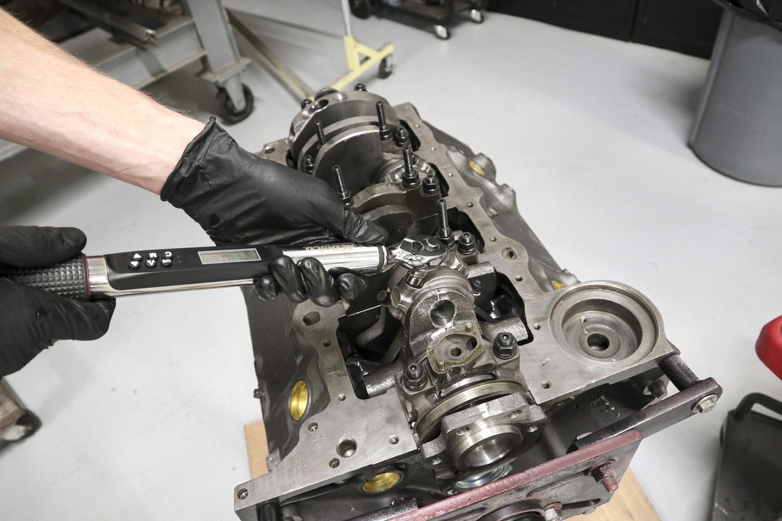
With the engine back at the In The Garage Media Tech Center we got to work assembling the short-block, beginning with installing our ARP main studs and the 0.030-inch over main bearings provided by Speedway Motors.We used a micrometer to measure the crankshaft journal diameter and, after torquing the first main cap to spec, a dial bore gauge to measure the bearing clearance. As it turned out, the bearings Speedway Motors provided with their rotating assembly were a perfect match.
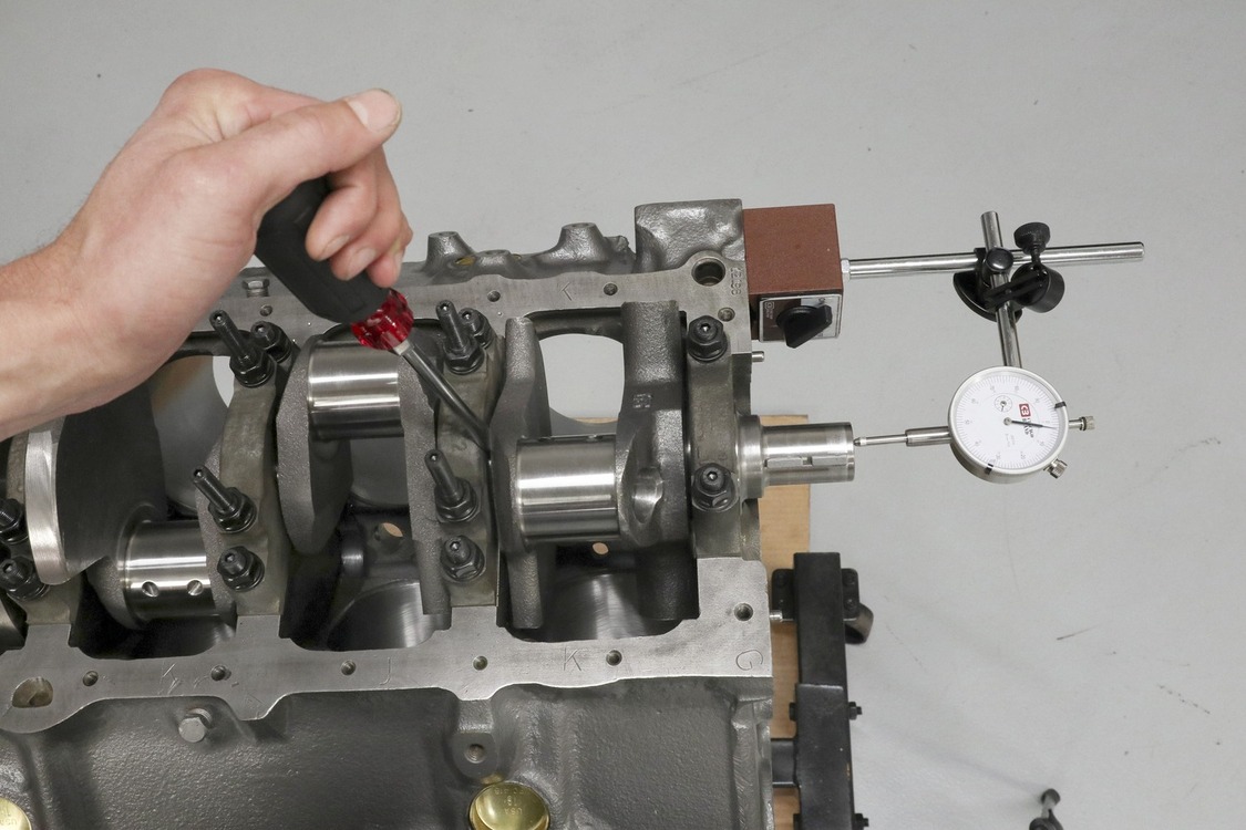
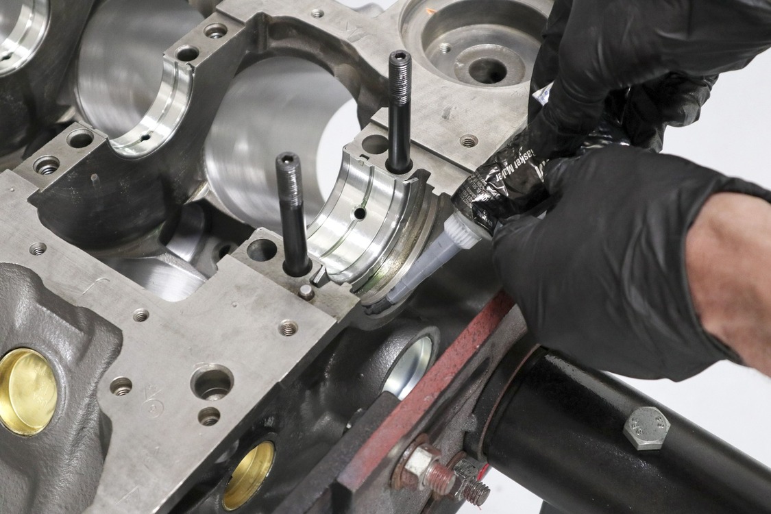
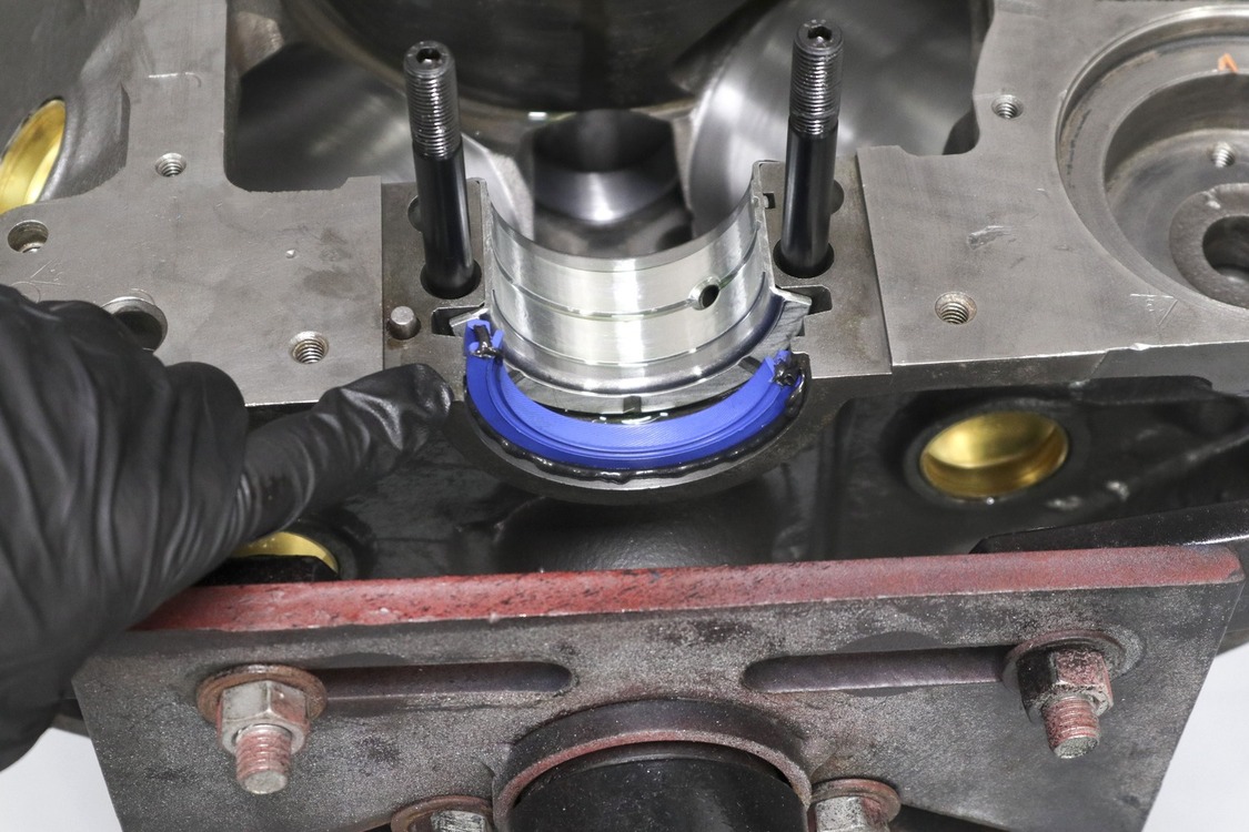
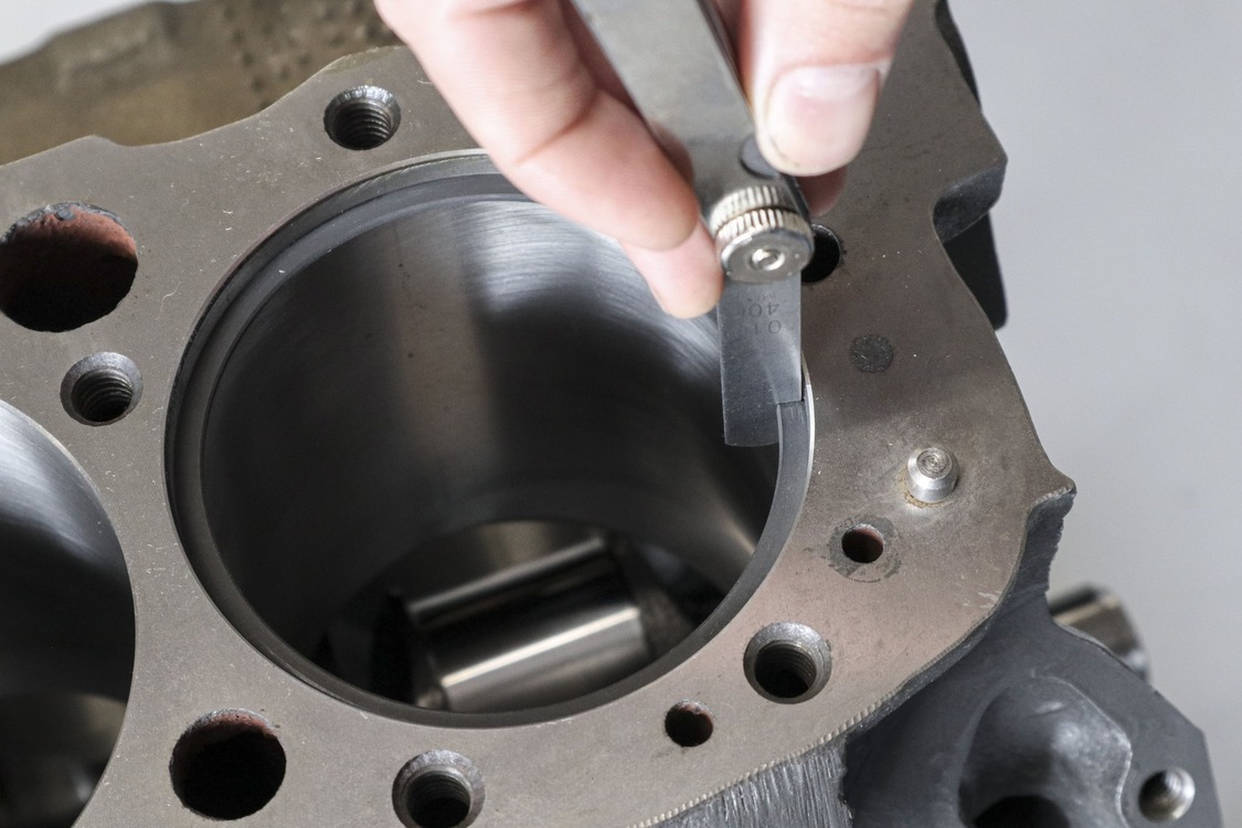
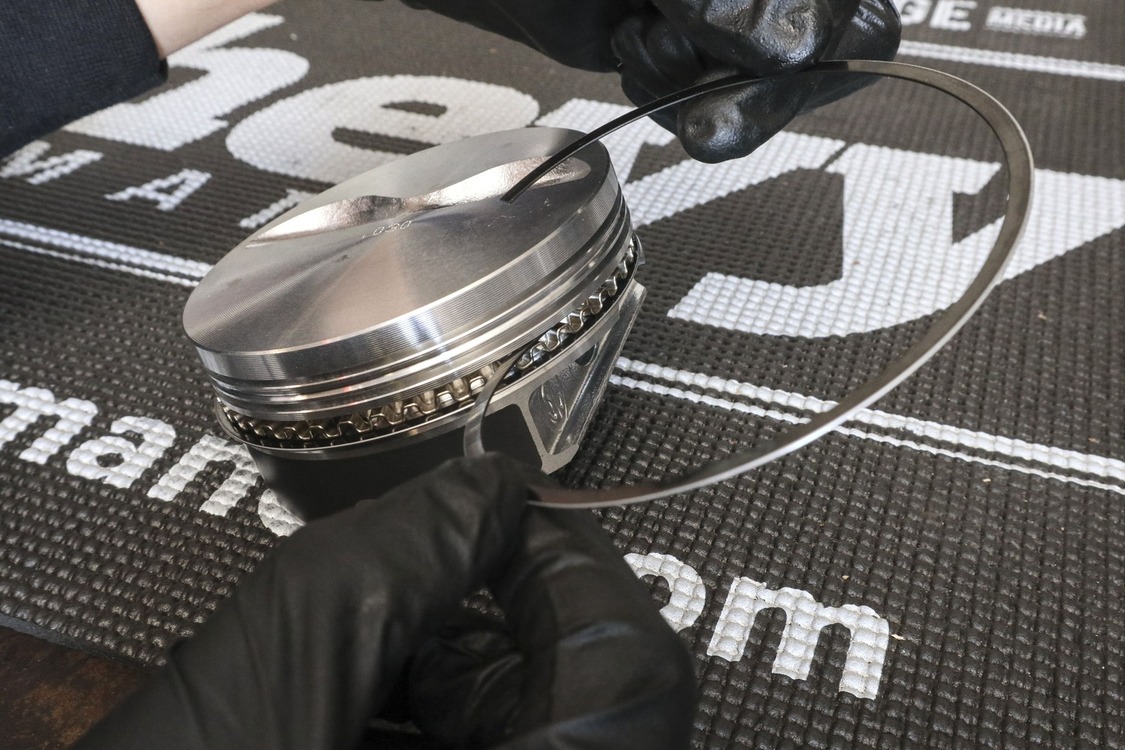
The next clearance to verify was the crankshaft endplay. With the crank installed and main caps properly torqued using ARP Fastener Assembly Lubricant, we fitted a dial gauge on a magnetic base squared to the crankshaft snout. Then, we used a long screwdriver between one of the main caps and crankshaft blades to pry the crankshaft fore and then aft, noting the amount of lateral movement on the dial indicator.With the crankshaft removed and briefly set aside, we proceeded to install the two-piece rear main seal using a light bead of black RTV on the backside of the upper and lower seal.For even more confidence, we offset the ends of the seal and added a small dab of RTV to each end. Don’t forget to add some oil on the inside lip of both main seal halves to help the crank spin freely.Next, we set our sights on preparing the pistons to go in their respective homes. We started by verifying we had the proper ring endgap on the Speedway Pro Series plasma moly-coated rings (this high-tech coating has been proven to increase horsepower through reduced friction).
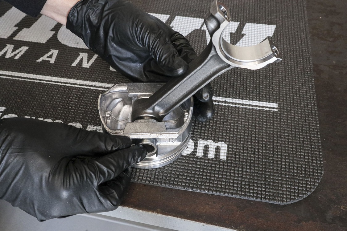
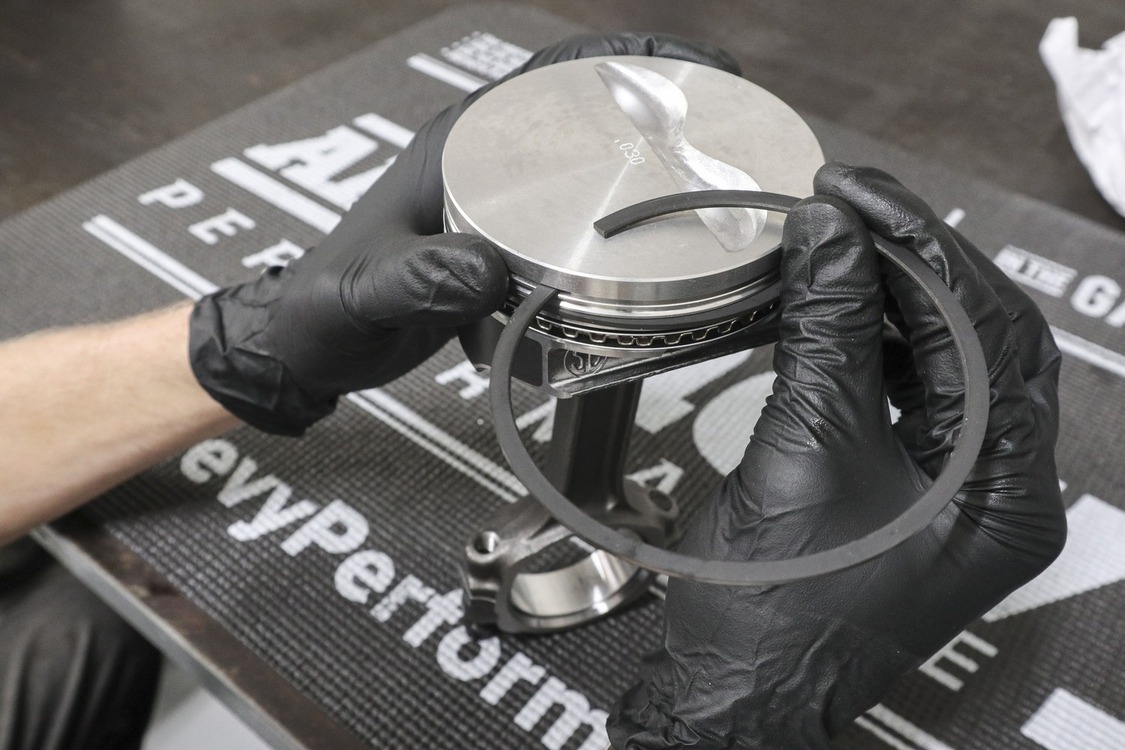
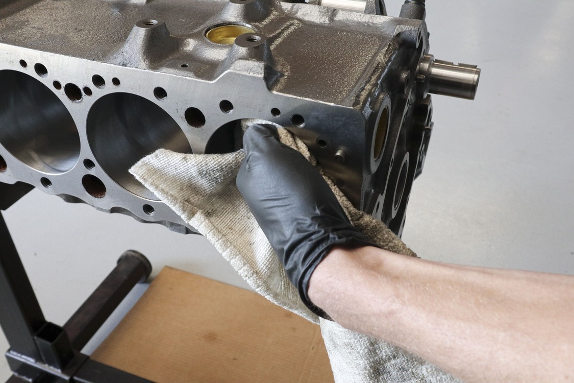
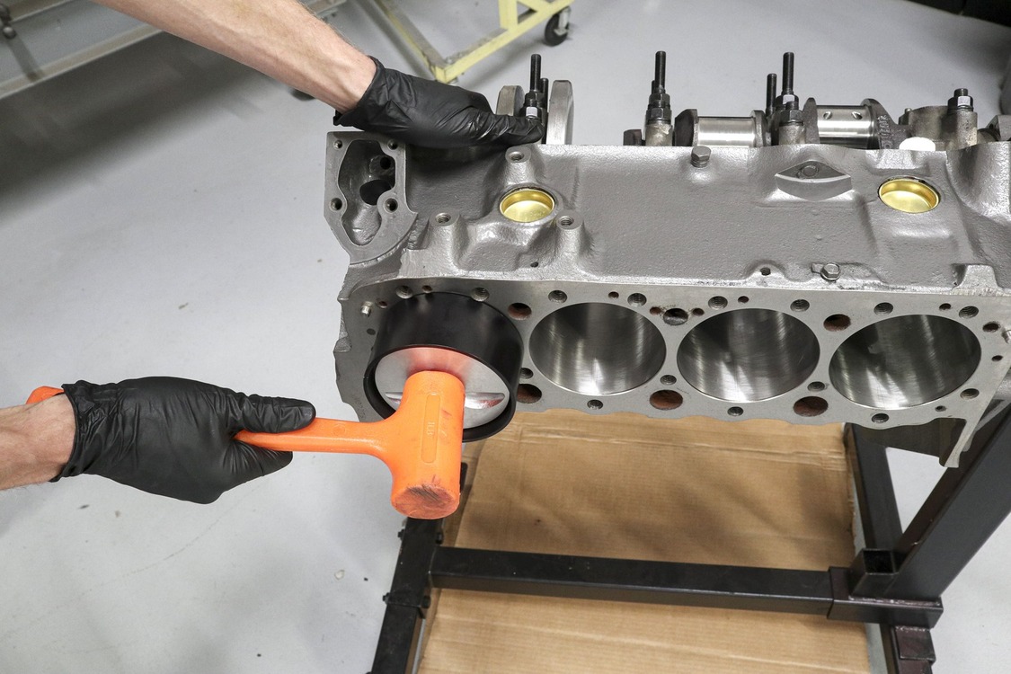
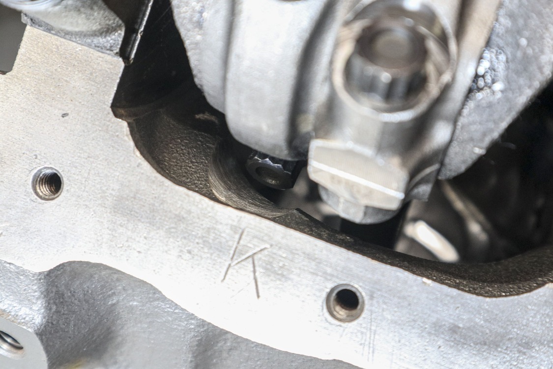
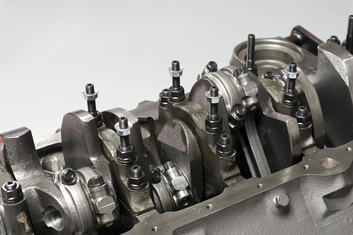
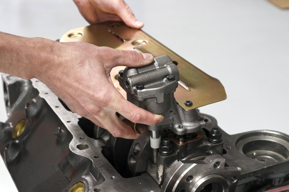
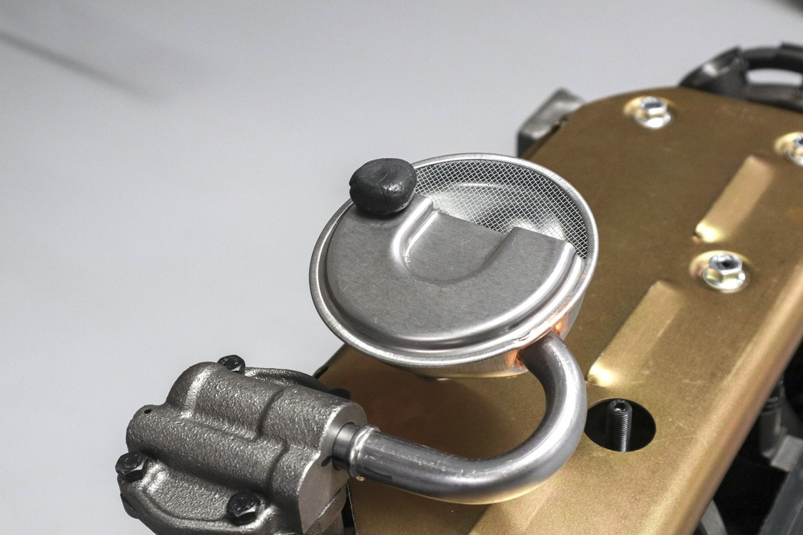
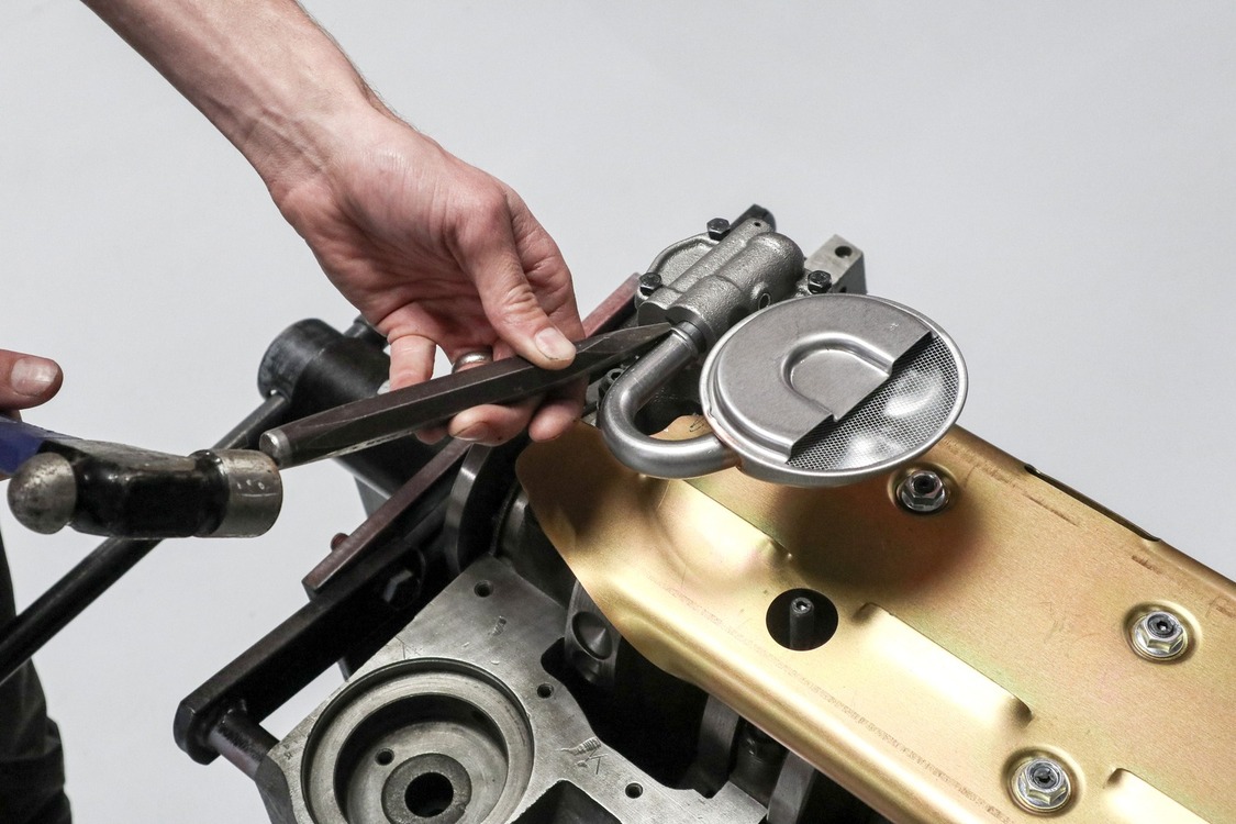
Then we installed the connecting rod bearings and double-checked the big end clearance using similar tools and techniques as we did for the main journals.A benchtop vise was necessary for securing the rod while torquing the bolts to spec and measuring the bearing diameter.Remember how we mentioned the piston pin eating into the oil ring land? Well, we didn’t! We had to carefully remove the oil rings we’d already installed on the first piston in order to actually fit the piston to the rod—oops!With that mishap sorted out, we proceeded to coat the wristpins with engine assembly lube, installed the rods on the pistons, securing them with the provided C-clips.We installed the rings on the pistons, making sure to offset each ring endgap for proper sealing. If the ring has a dot or dimple present that side faces the top of the engine. If there’s no marking, the chamfered side typically goes up.After a final wipe down of each cylinder with a lint-free rag and some acetone, we coated the cylinder walls with a healthy dose of engine assembly lube. This protects the bare steel from forming any rust in case the engine sits for a while after being assembled.It was finally time to send home the hypereutectic flat-top pistons. A billet piston installation tool sized for 4.030-inch pistons and a rubber mallet made this a step a breeze.Then we installed the connecting rod caps. After torquing the bolts on each cap to spec, we made sure the rotating assembly still turned over freely.Check out that rod bolt clearance. Derek Jr. really nailed the block modifications to give us just enough room for our longer rods.With the stroker rotating assembly installed in our small-block, we decided to finish off the lower portion of the engine by fitting our windage tray and Speedway Motors oil pump. We used the hardware provided with our ARP main stud kit to set the height of the tray.We fitted the other half of the oil pump shaft then dropped in the oil pump and windage tray together. With everything bolted down, we made sure to double-check our clearance when turning the engine over.To set our pick-up angle, we began by lightly tapping the tube into the pump. Then we used a small piece of putty to check clearance between the bottom of our oil pan and the lowest point of the pickup (with our oil pan gasket installed, of course!).Using the flat end of a chisel, we proceeded to fully seat the pick-up tube in the pump. Then, for a little extra peace of mind, we burned it in place with a little tack weld.
We use cookies to ensure that we give you the best experience on our website. If you continue to use this site we will assume that you are happy with it.