ITGMw
SUBSCRIPTIONtext
ProgressArrows
digital issues
ProgressArrows
online store
ProgressArrows
SUBSCRIPTIONtext
ITGMw
ACPnew header logo
CTP LOGOs
all cars

How To Make A Recessed License Plate Holder

Tin Man’s Garage’s Custom License Plate

By Ron Covell   –   Photography By Brian Limberg

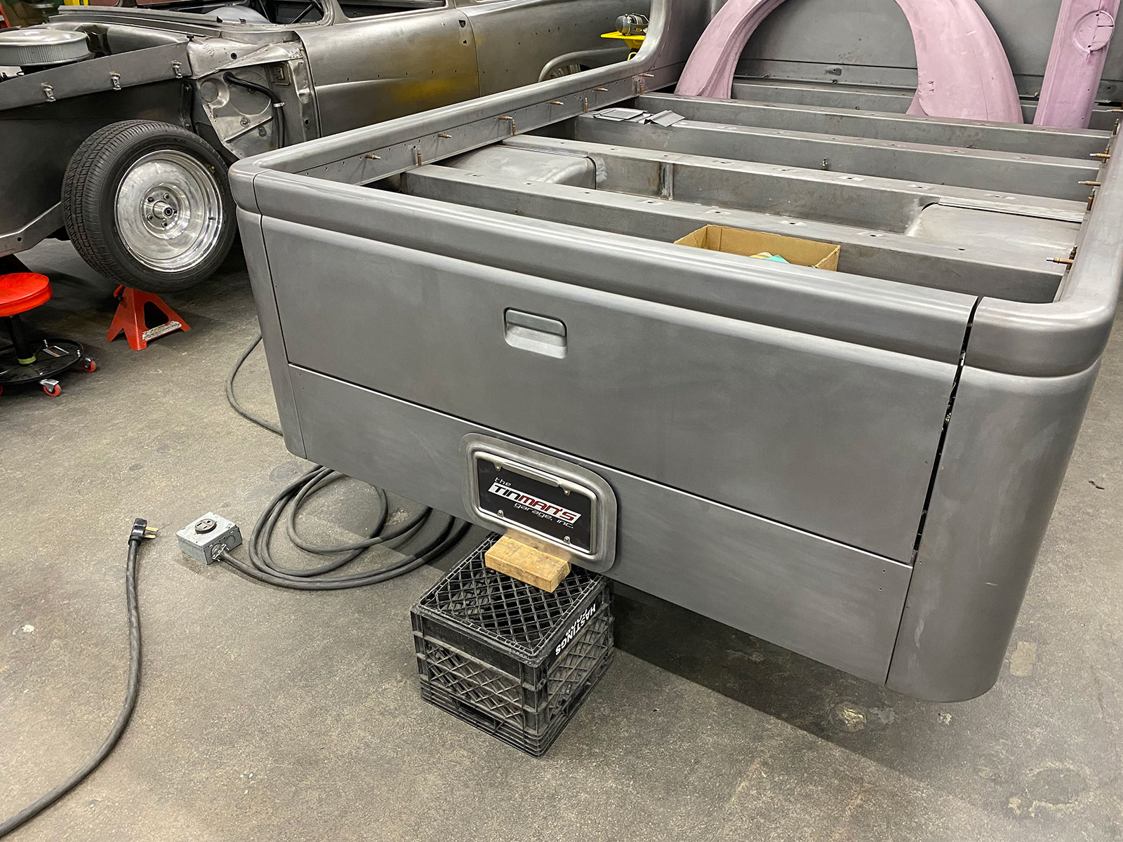
Brian Limberg, the founder of Tin Man’s Garage in Sycamore, Illinois, is no stranger to high-level metalworking. He has been refining his craft for many years, and his team has received some of the highest honors achievable. Last year they received the Al Slonaker award at the 2022 Grand National Roadster Show in Pomona, California, with the outstanding 1936 Willys pickup they built. In this article we’ll focus on a beautifully executed recess for a license plate, which Tin Man’s Garage crew member Elijah Schroeder fitted to the rear of a 1937 GMC cabover bed that they built from scratch.

Read More: 1936 Ford Coupe Turned AMBR Contender

02 The first step was hand carving a block of polystyrene insulation foam to visualize the proportions
The first step was hand carving a block of polystyrene insulation foam to visualize the proportions of the raised rib and the recess for the license plate.

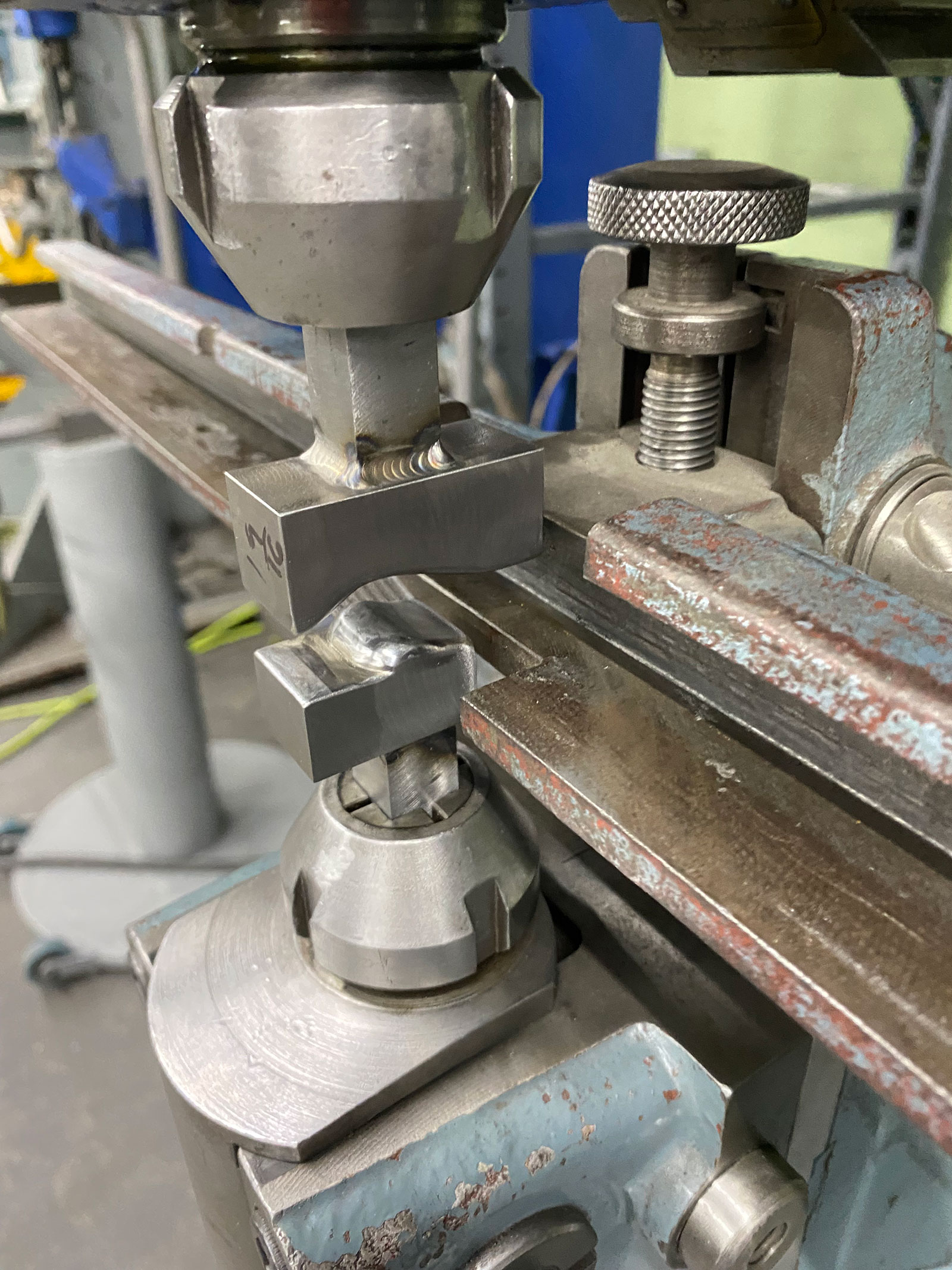
The main forming tool used for this project is a Pullmax machine, and while there are other tools that could do this job, an “electric reciprocating” machine has several advantages—one of the most important being the ease of making specialty tooling to precisely create the desired profile on the panel.

03 Once the desired profile was finalized two blocks of steel were contoured to make the male and female dies
Once the desired profile was finalized, two blocks of steel were contoured to make the male and female dies.

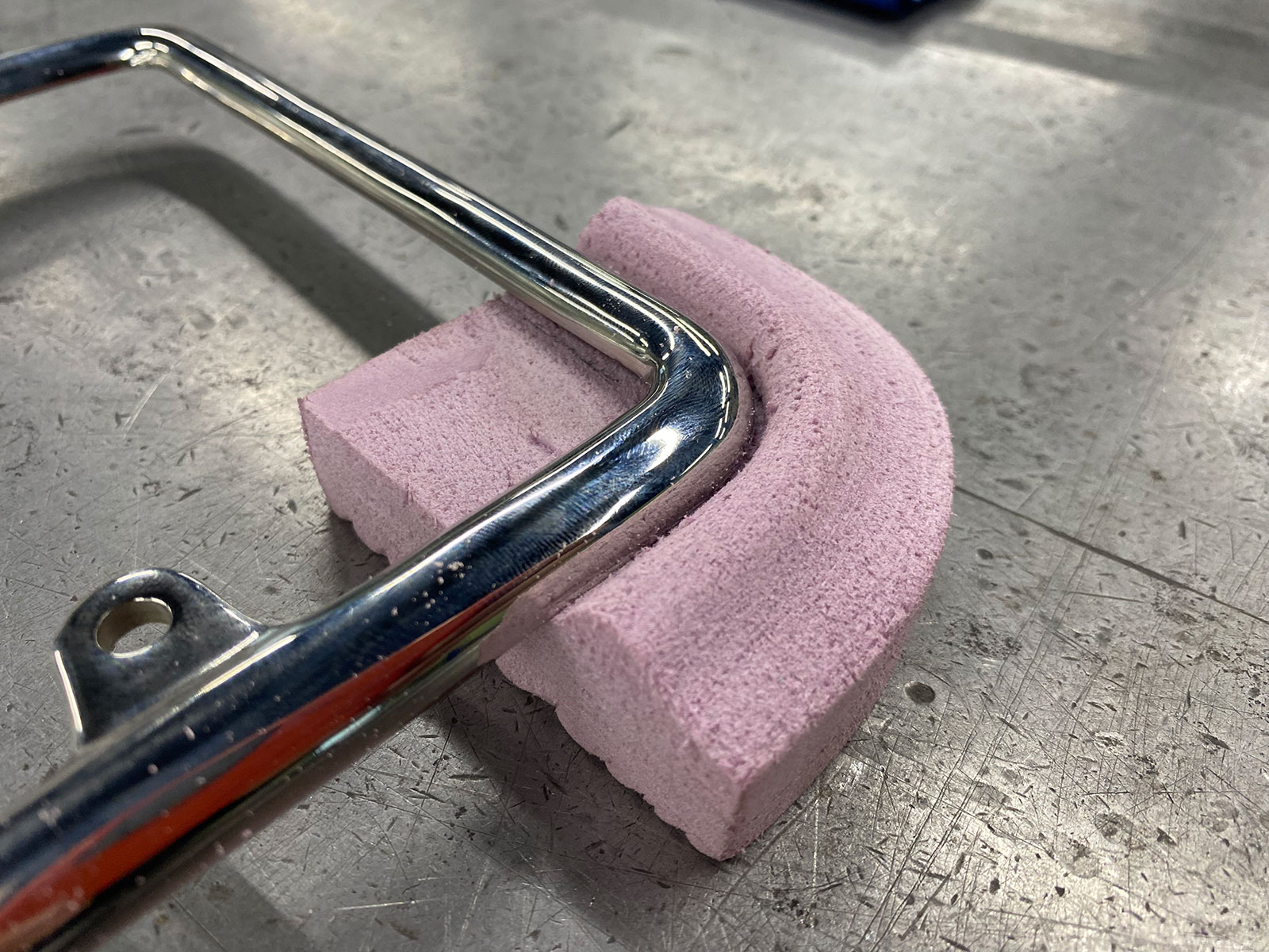
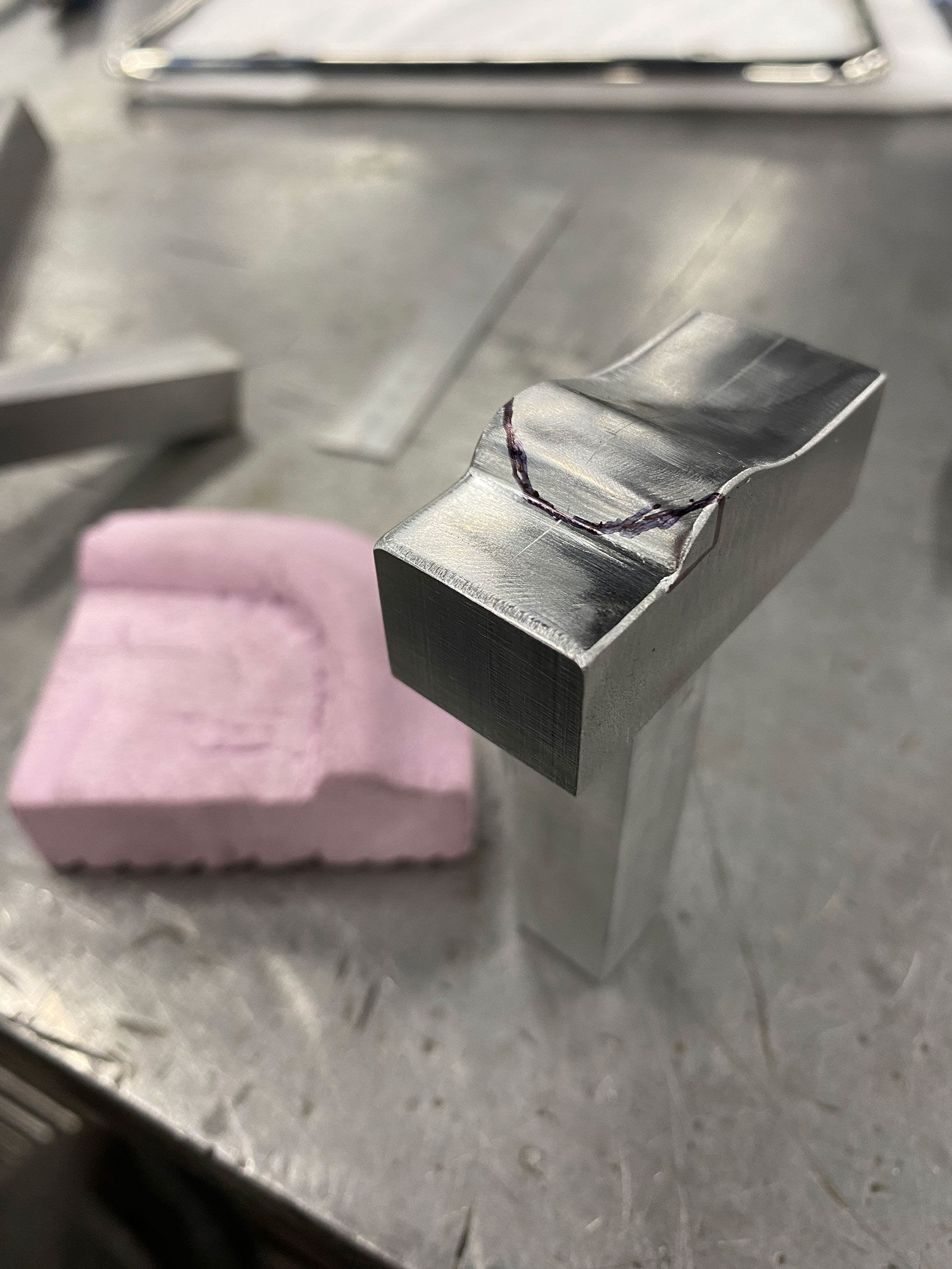
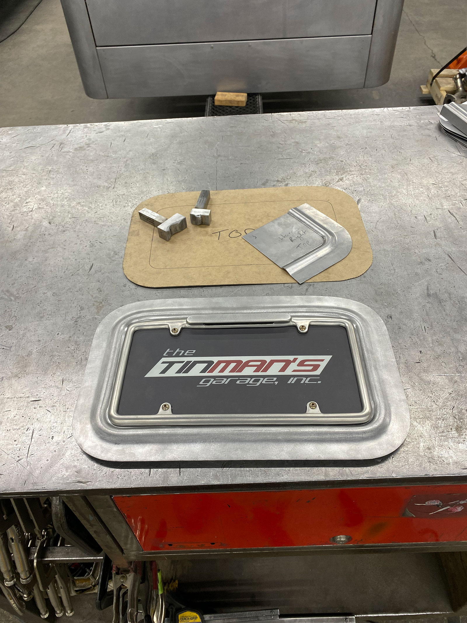
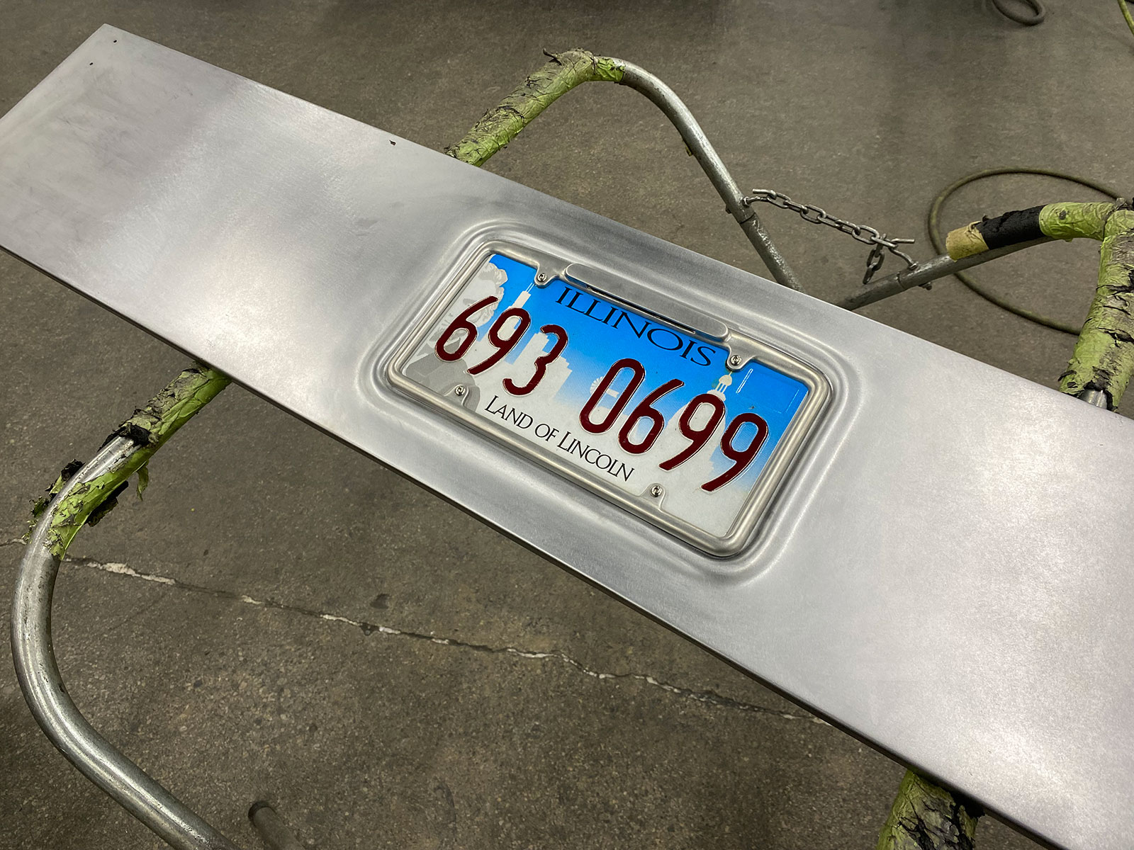
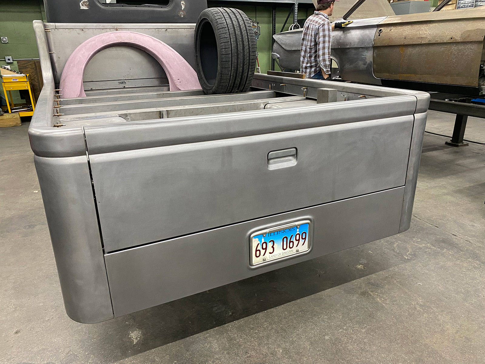
Elijah started by making a simple foam mockup for one corner of the recess, which allowed him to visualize the fit with the illuminated license plate frame they selected. The goal was to put a raised rib in the panel, leaving a recess just slightly larger than the frame’s outside dimensions, with the rib nearly as high as the frame. The rib profile has a soft lead-in on the outside, with the inside a bit sharper to complement the design of the license plate frame. He sanded the foam mockup by hand, and once he was satisfied with the contours, it was used as a guide to make the tooling to do the forming.

Read More: How To Cut and Buff Like a Professional

04 jpgThese dies are designed to work in a Pullmax machine
These dies are designed to work in a Pullmax machine. A fixture is being used here to ensure the alignment of the stems that hold the dies in the machine.

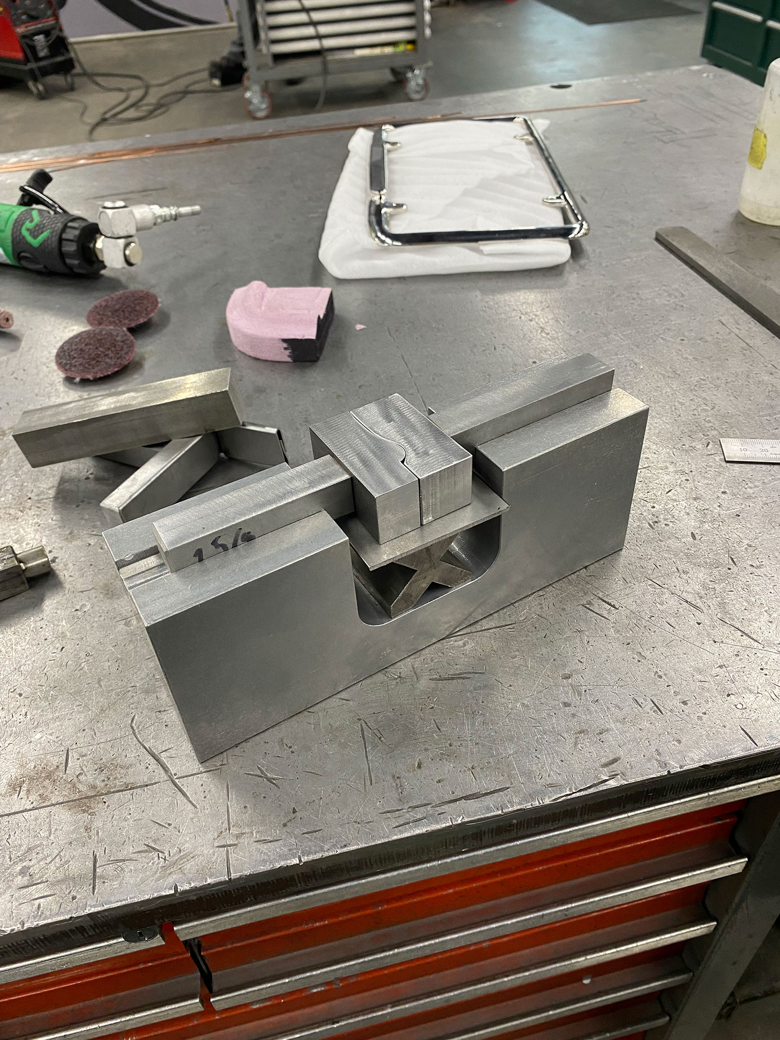
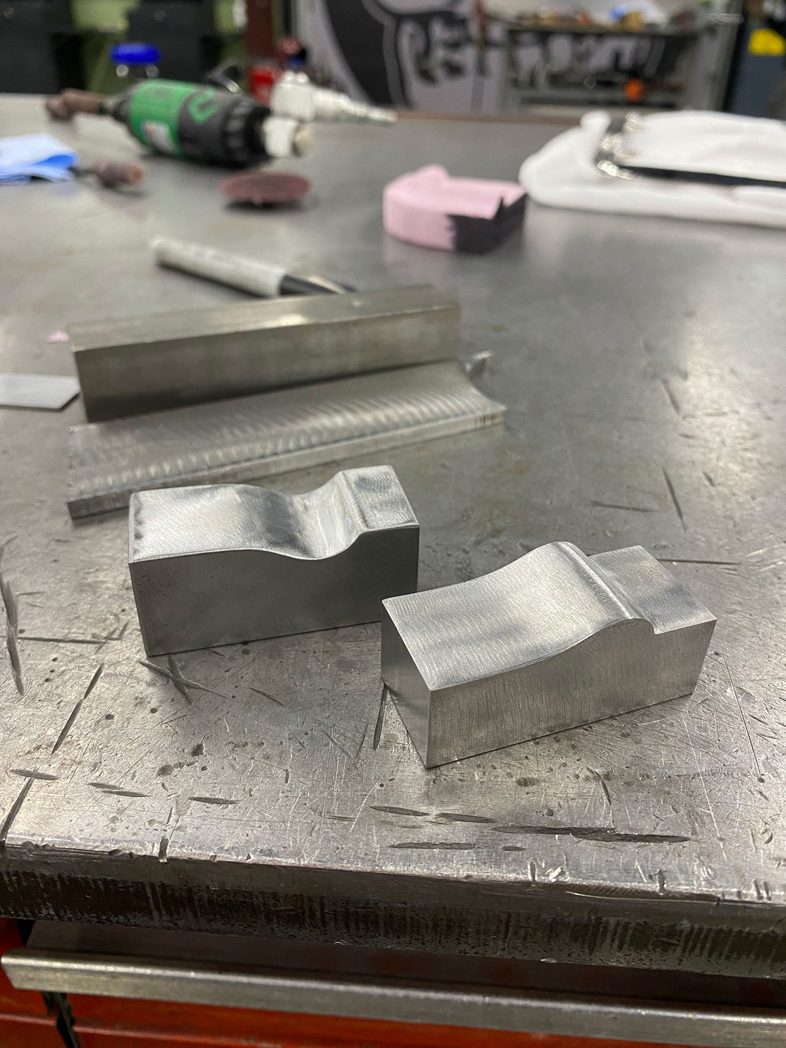
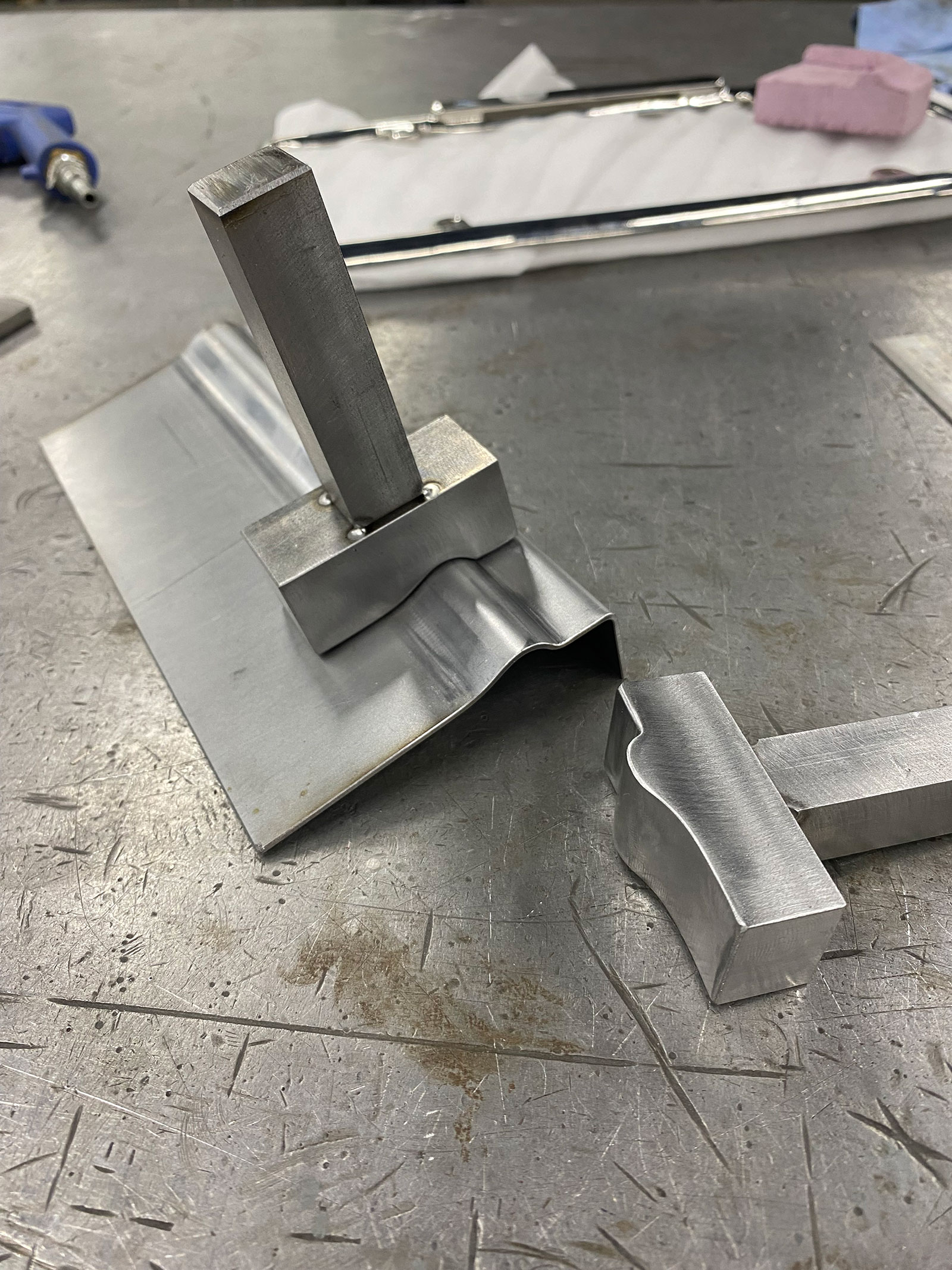
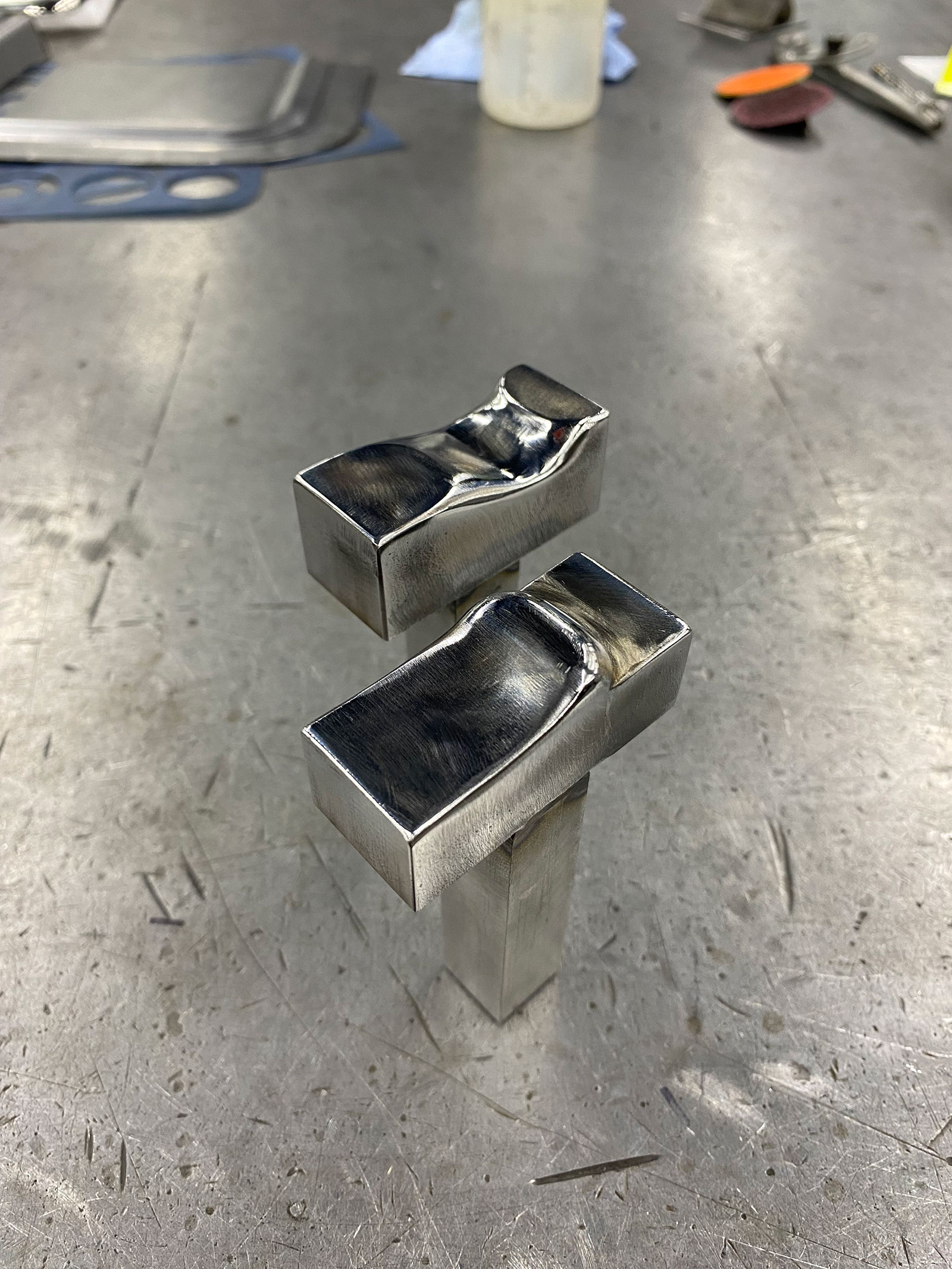
The tooling consists of two blocks of steel, one male and one female, that fit together with a one material thickness gap between them. Mounting shafts were tack welded to the dies to match the square collets in the Pullmax machine. The dies were tested on a straight strip of scrap material and once they were tuned to form the profile exactly as desired, they were finish welded to the shafts. The male die had to be relieved to traverse the tight-radius corners. This was carefully done with hand tools, then the dies were polished.

05 The shafts are only tack welded at this stage in case any adjustment is required
The dies are tried out in the machine. The shafts are only tack-welded at this stage in case any adjustment is required.

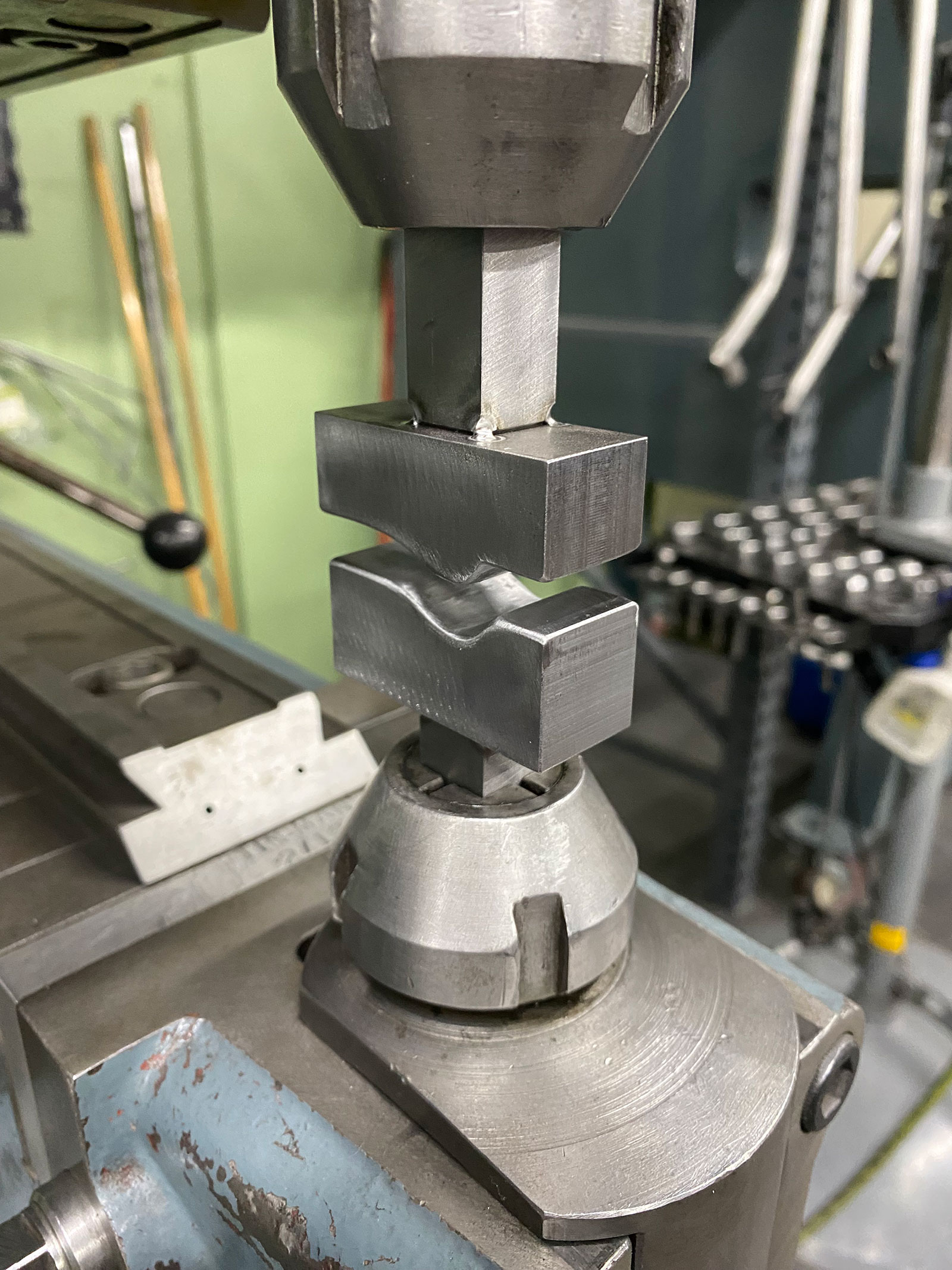
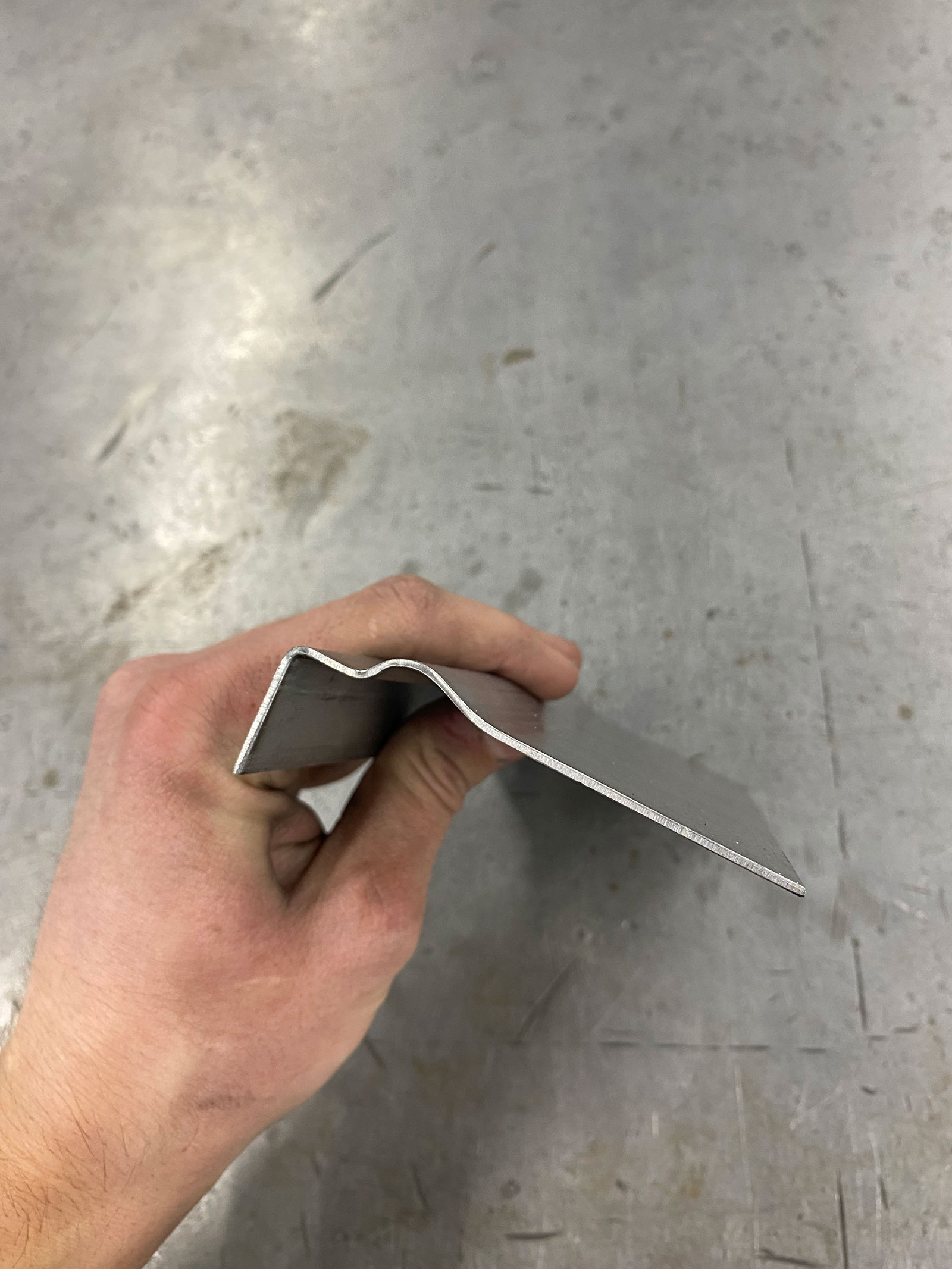
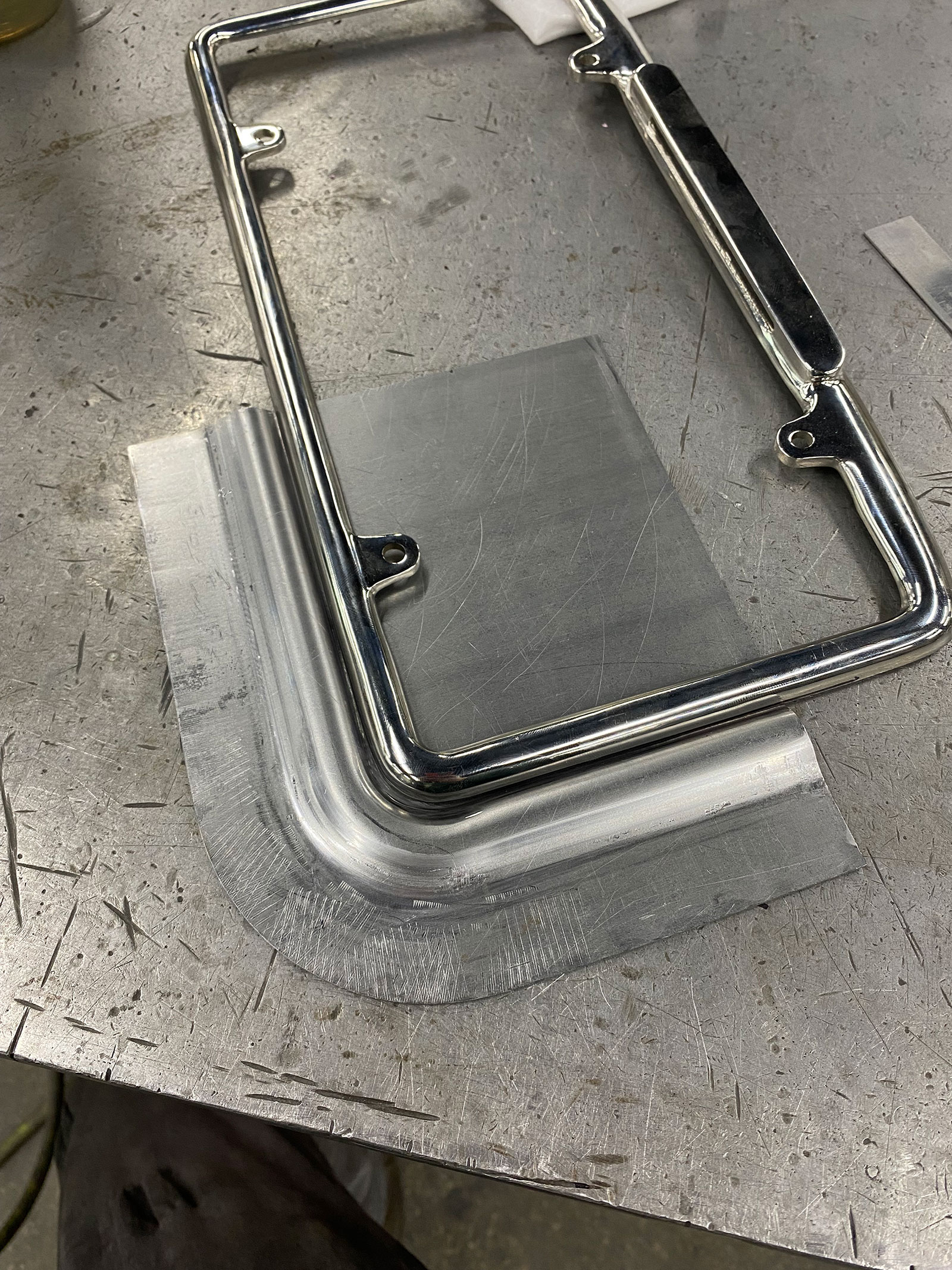
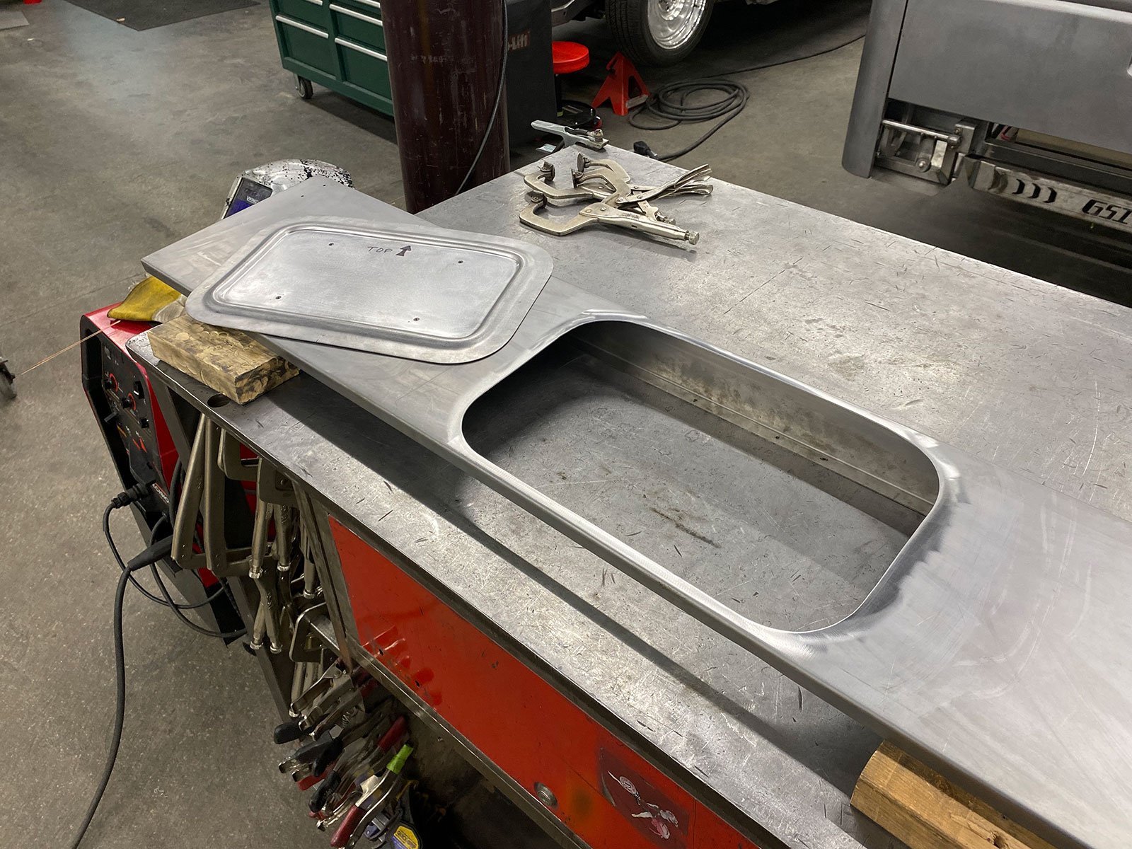
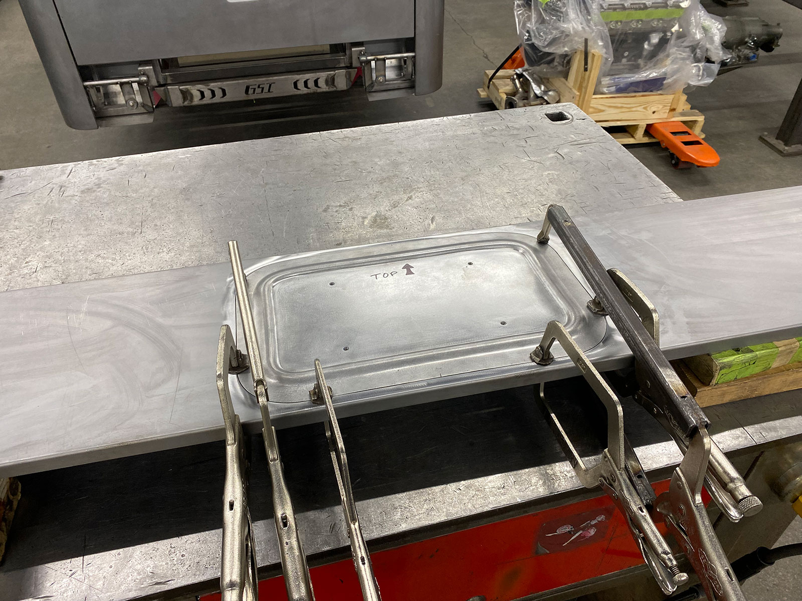
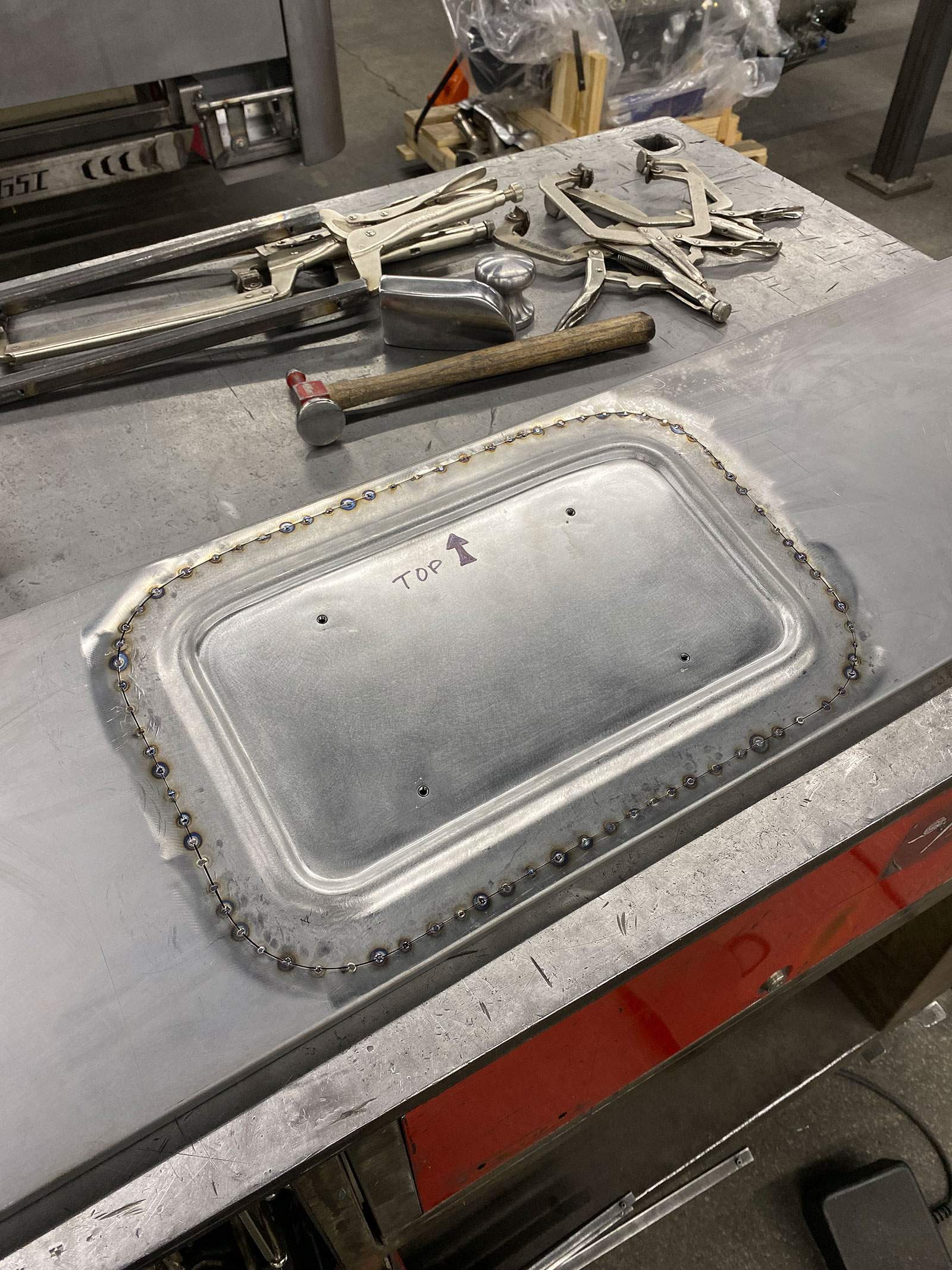
When forming details like this in a Pullmax machine, the blank needs to be moved precisely, allowing the feature to be formed to the right size and contour. This was accomplished by using a fence on the Pullmax machine. A blank was made with a 1-9/16-inch border outside the raised rib. The edge of this blank was held tight against the fence, and the lower die was raised a little each time the part was rotated through the oscillating dies, until the full depth was reached. As you can see in the photos, the rib was formed so cleanly that very little tune-up work was required.

Read More: Jimmy Summers’ Timeless Ford Custom

06 Here’s a test strip of metal that’s been run through the dies
Here’s a test strip of metal that’s been run through the dies. The flange on the left guides the metal in a straight line as it runs through the dies.

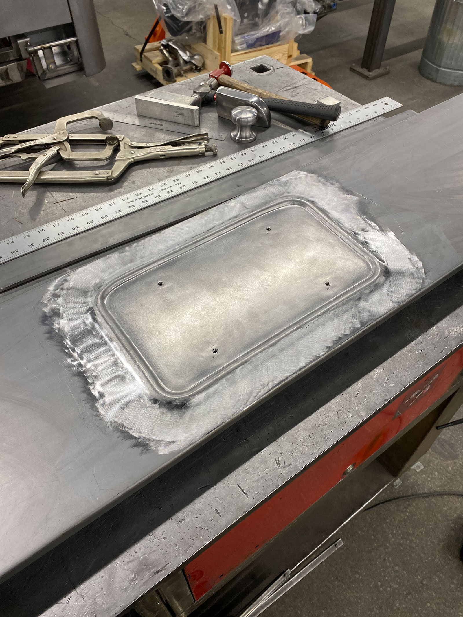
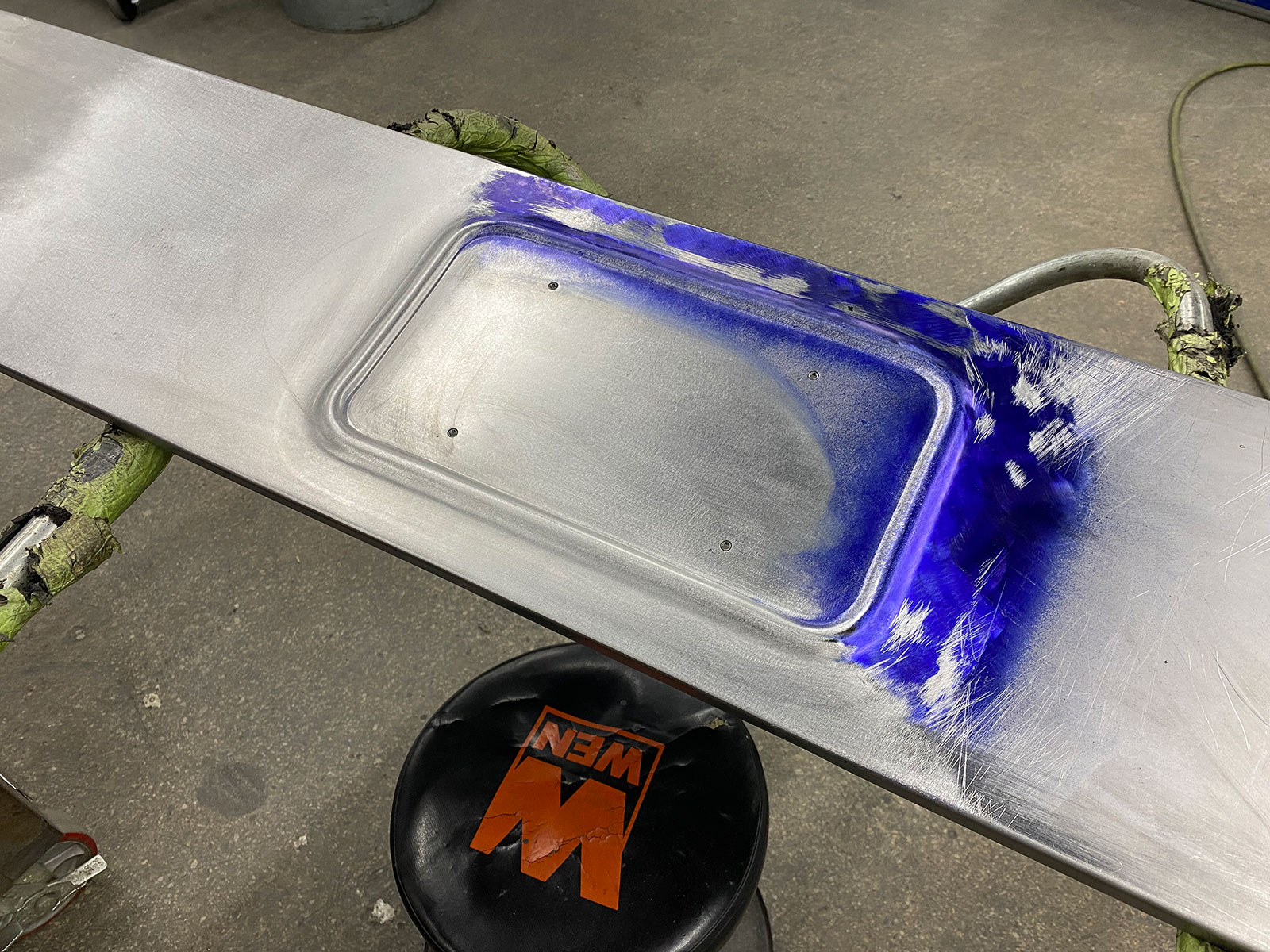
The final step was to cut an opening in the rear panel of the truck, then weld the newly formed panel into place and metal finish it. As you look through the photos you’ll see the key steps in the process. MR

07 The test shows that the dies are meshing perfectly
Another view of the dies and the test piece. The test shows that the dies are meshing perfectly.
08 The male die needs to be relieved to allow it to make the tight radius curves in the corners
The male die needs to be relieved to allow it to make the tight-radius curves in the corners. The material to be removed is outlined with black ink.
09 Here’s a test piece used to check the die’s action as they navigate the tight corner
Here’s a test piece used to check the die’s action as they navigate the tight corner. In this case, the edge of the panel is guided by a fence on the machine.
10 After the dies are shaped tested and proven the working surfaces are polished so they will leave a smooth finish on the panel
After the dies are shaped, tested, and proven, the working surfaces are polished, so they will leave a smooth finish on the panel.
11 Here’s the fence used to guide the edge of the metal for both the straight runs and the curves
Here’s the fence used to guide the edge of the metal, for both the straight runs and the curves.
12 You can see the fit against the license frame is spot on
This is the finished piece after running the panel through the dies repeatedly, working incrementally toward full depth. You can see the fit against the license frame is spot-on.
13 The formed piece of metal is tested to find the perfect location on the rear panel
The formed piece of metal is tested to find the perfect location on the rear panel. Then it’s clamped into place and the edges are scribed for trimming.
14 The center of the panel is trimmed out here in preparation for butt welding the license recess into place
The center of the panel is trimmed out here in preparation for butt-welding the license recess into place.
15 Clamps are used to align and secure the panel for the tack welding
Clamps are used to align and secure the panel for the tack-welding.
16 A TIG welder is used to tack weld the panel with the tacks spaced about 5 8 inch apart
A TIG welder is used to tack-weld the panel, with the tacks spaced about 5/8-inch apart. After tacking, the joint is worked with a hammer and dolly to stretch the tacks, straightening any distortion.
17 After welding and hammering the welding bead is sanded flush
After welding and hammering, the welding bead is sanded flush.
18 Blue Dykem is used to show the low spots as the panel is carefully metal finished
Blue Dykem is used to show the low spots as the panel is carefully metal finished.
19 With the metal finishing completed it’s impossible to see the welded joint
With the metal finishing completed, it’s impossible to see the welded joint.
20 The finished panel is mounted back on the bed of the truck
The finished panel is mounted back on the bed of the truck. This is a cool detail that really adds a lot of class to the project.

Source
Tin Man’s Garage
(815) 991-5308
tinmansgarage.com

Related Articles

Search Our Site