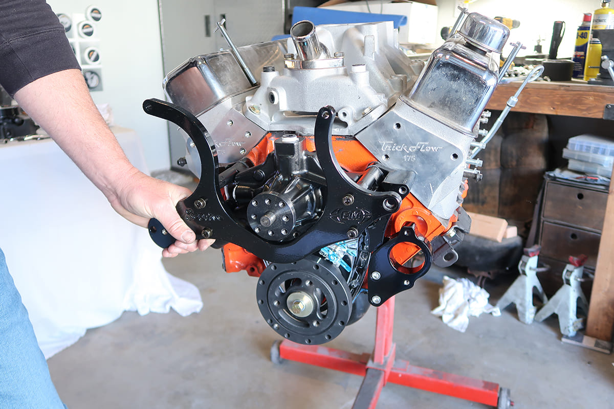
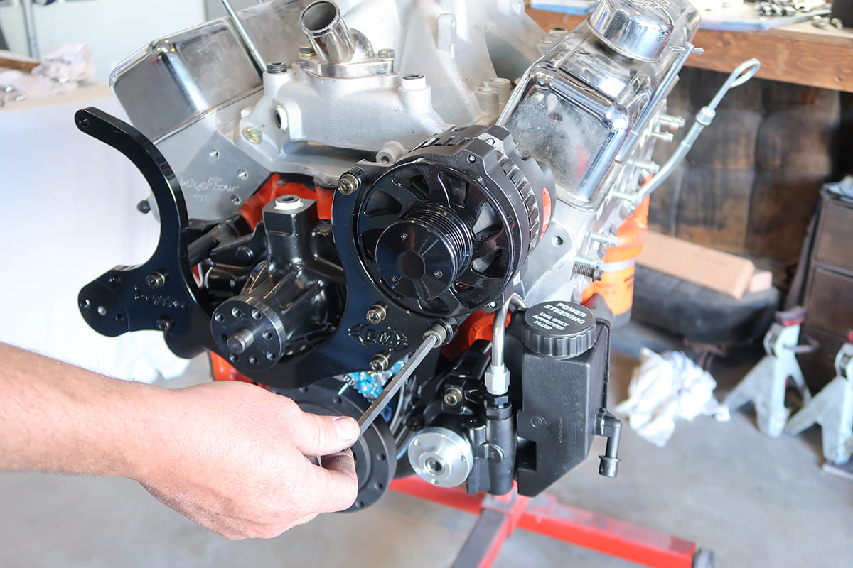
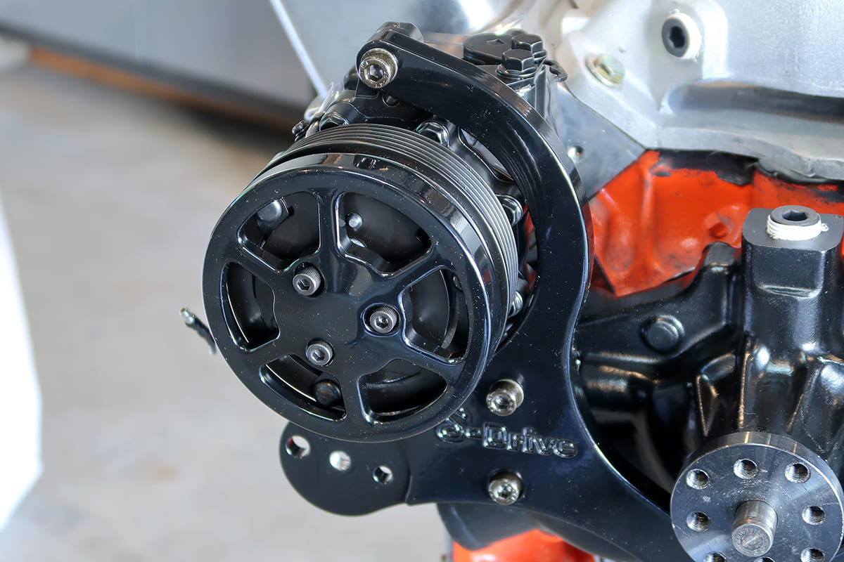
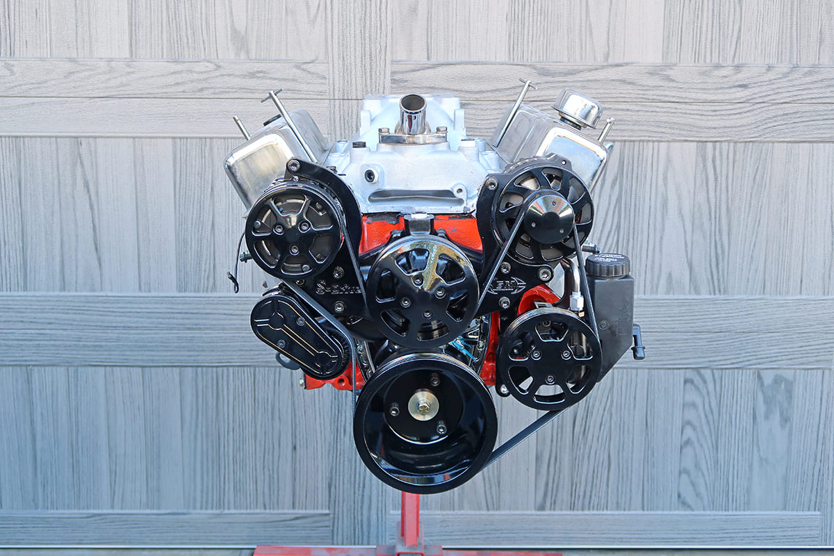
Eddie Motorsports offers their S-Drive serpentine belt kits in a variety of finishes. This is the new all- black Raven Series being installed on a small-block destined for a 1967 Chevelle.
Say Goodbye to Multiple V-belts with an Eddie Motorsports Serpentine System
Many of our favorite cars wearing a Chevrolet nameplate were produced decades ago, but while we may love those vintage vehicles, there’s no disputing they can often benefit from more recent technology. Things like electronic ignition, fuel injection, and an overdrive transmission are common updates. Of course there are less-complicated improvements that can also have a big impact. One example is a serpentine accessory drive system.
Rather than multiple V-belts and the stacked pulleys that are often required to spin engine-driven accessories, a serpentine system uses a single belt. The obvious advantage is that a lone belt with all the pulleys on the same plane takes up much less room on the front of the engine. There are also a number of other reasons to make the switch. A single, flat belt is much more efficient than multiple V-belt drives due to reduced friction. And the use of an automatic tensioner reduces maintenance and allows all the engine-driven accessories to be mounted solidly, as they don’t have to be moved to tighten the belt. Another benefit is the spring-loaded tension absorbs harmonics that occur in the drivebelt in operation. In addition, if a serpentine belt has to be changed it eliminates the need to remove and readjust a number of other belts, which is often the case with V-belts.
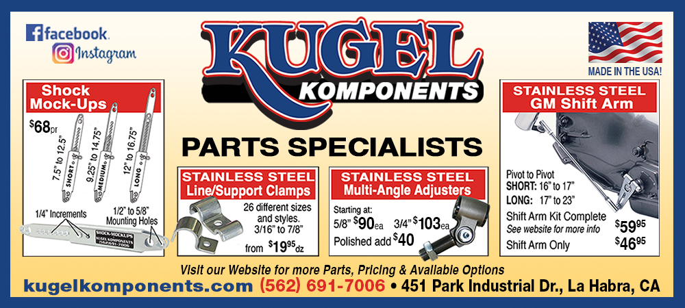
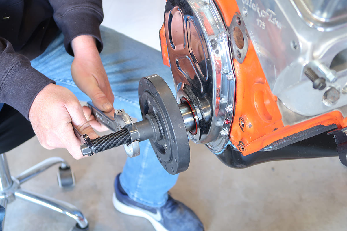
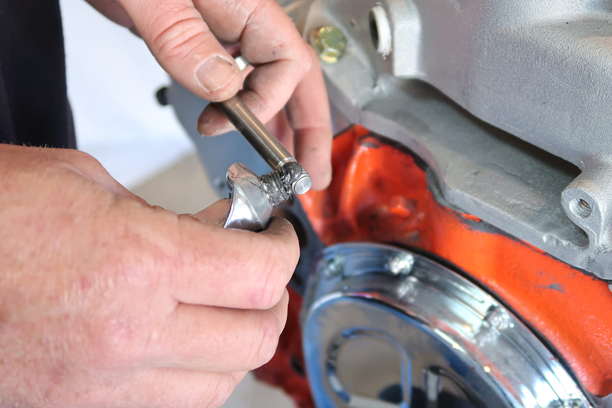
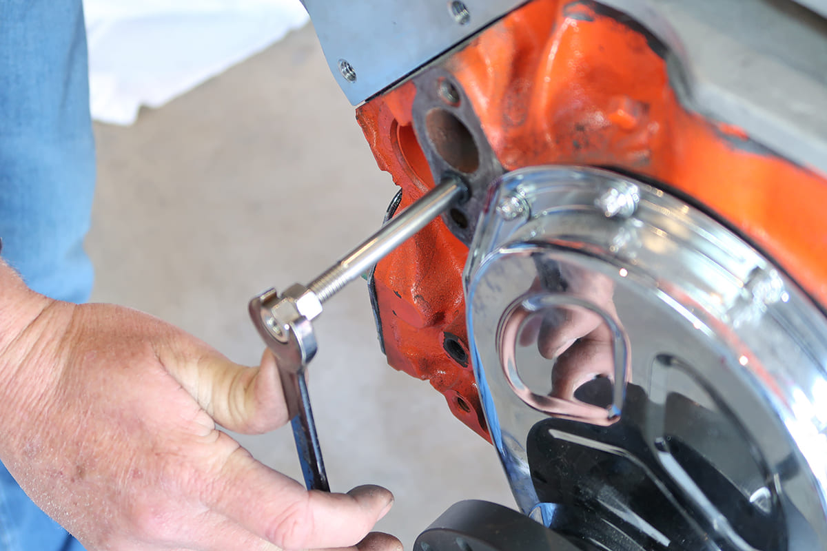
The only special tools required to install an S-Drive system are pullers to remove and replace the vibration damper. Never pull on the outside ring of the damper and resist the urge to drive it back on with a hammer.
While it may come as a shock to the red, white, and Bowtie Brigade, it was Ford that first introduced serpentine drivebelts on production cars. According to an article published in a Kansas newspaper, Great Bend Tribune, a native of that state by the name of Jim Vance developed the serpentine drive system in 1974 while working for the Gates Rubber Company. The design received a patent and was offered to General Motors, but they passed. However, Ford thought it was a better idea and introduced serpentine belts on Mustangs in 1979. By 1982 GM followed suit and today virtually every new car and truck is so equipped. Fortunately for those who want to add a serpentine drivebelt system to a Chevrolet engine without one, be it a small-block, big-block, or LS, Eddie Motorsports has everything you need to make the switch.
All the hardware included in the S-Drive kits is made from stainless steel. To prevent galling of the fasteners, apply anti-seize compound to any threads not calling for sealer.
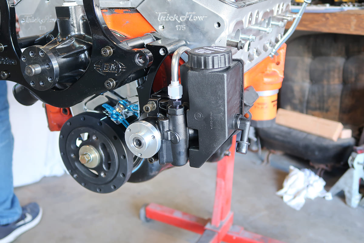
All of the Eddie Motorsports serpentine kits contain CNC-machined billet aluminum brackets and pulleys, all of the necessary stainless steel fasteners, an aluminum water pump, Powermaster 170-amp alternator, Gates tensioner and serpentine belt, Sanden A/C compressor, and a GM Type II power steering pump. Standard S-Drive kits come with a six-rib belt and pulleys while the S-Drive Plus series feature an eight-rib belt and pulley set. Designed for high-performance applications, the S-plus series will handle 33 percent more torque and horsepower than standard six-rib systems. All S-Drive kits are available in raw machined or highly polished finish as well as a variety of anodized or Fusioncoat colors.
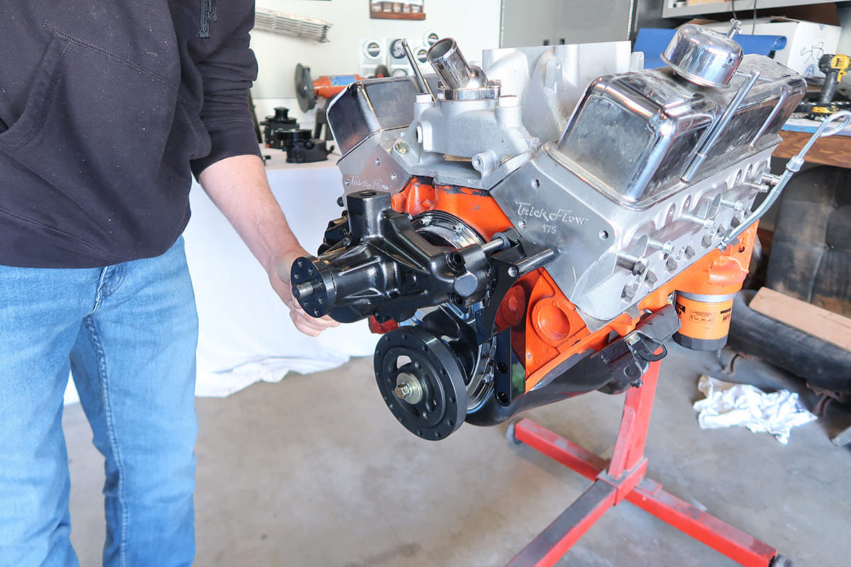
In addition to being beautifully executed and engineered, Eddie Motorsports S-Drive systems are simple to install. All Chevy engines retain the stock timing chain cover and small- and big-block kits use the water pump attachment points and existing holes in the block and heads as mounting points. LS engines require the drilling and tapping of one hole. Regardless of the engine involved, installing an S-Drive kit is the easy way have all the benefits of a serpentine drivebelt—and say goodbye to those multiple V-belts and hello to the single scene.
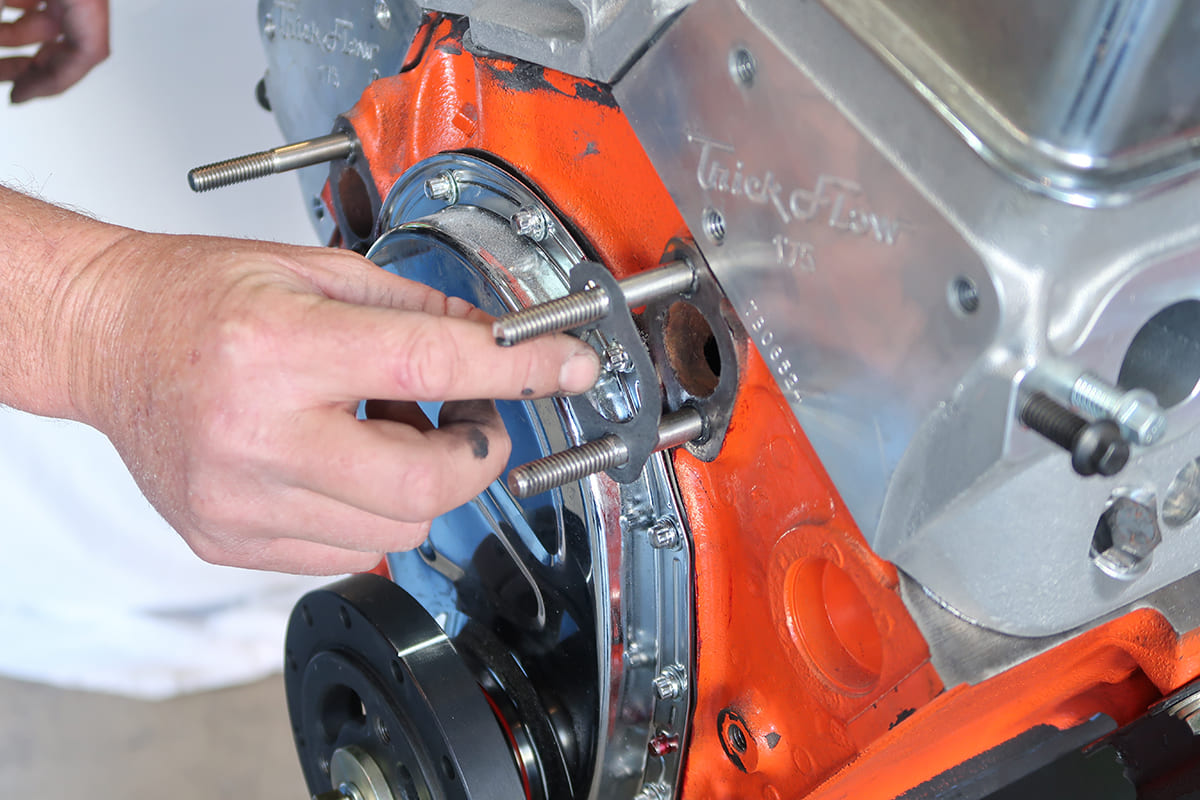
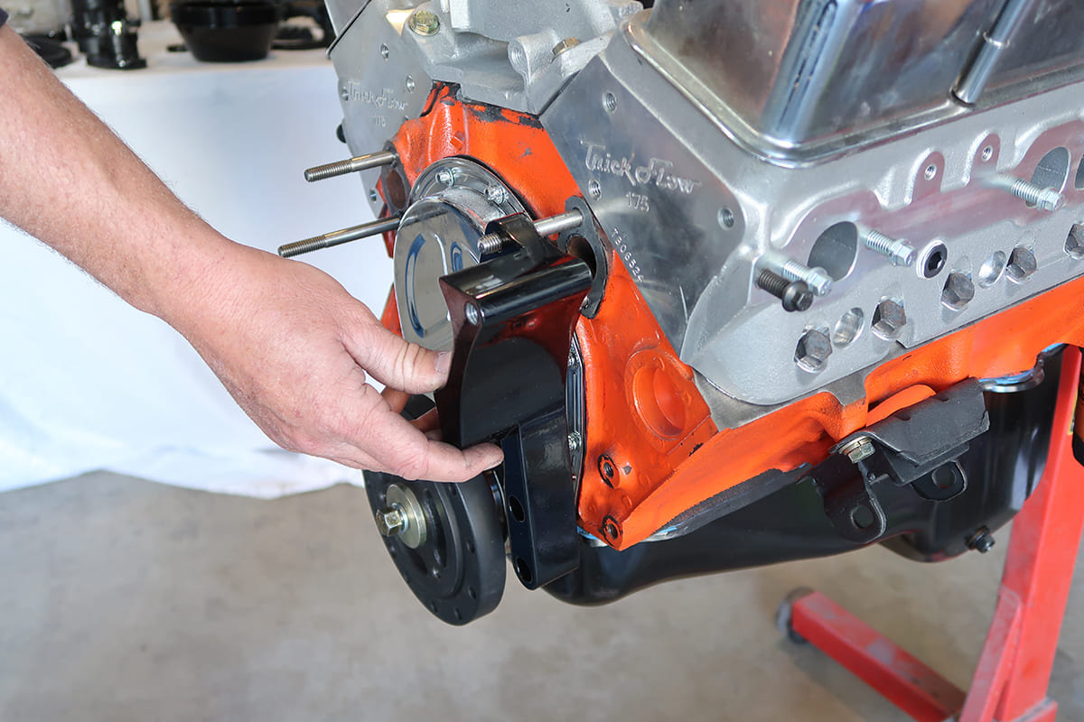
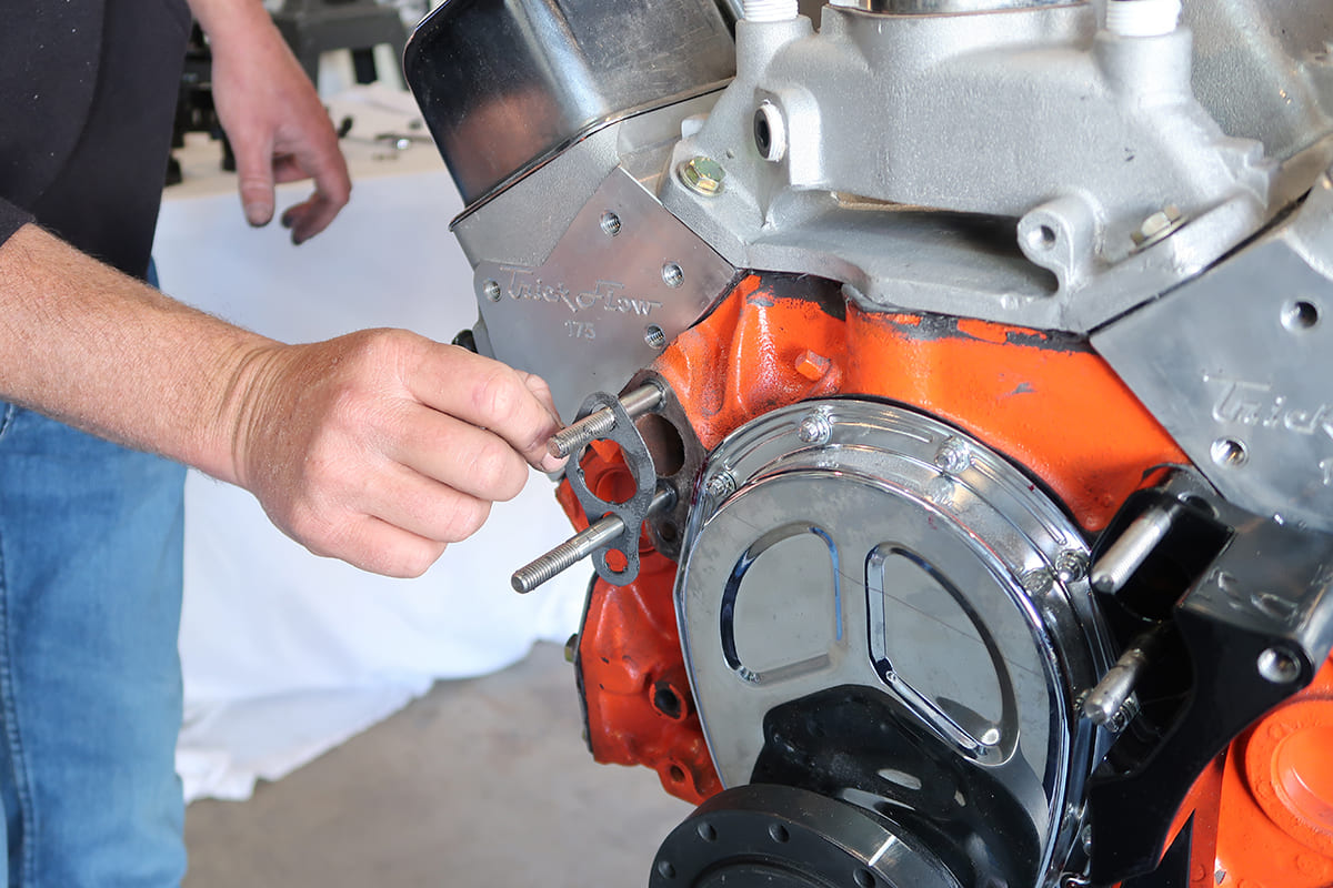
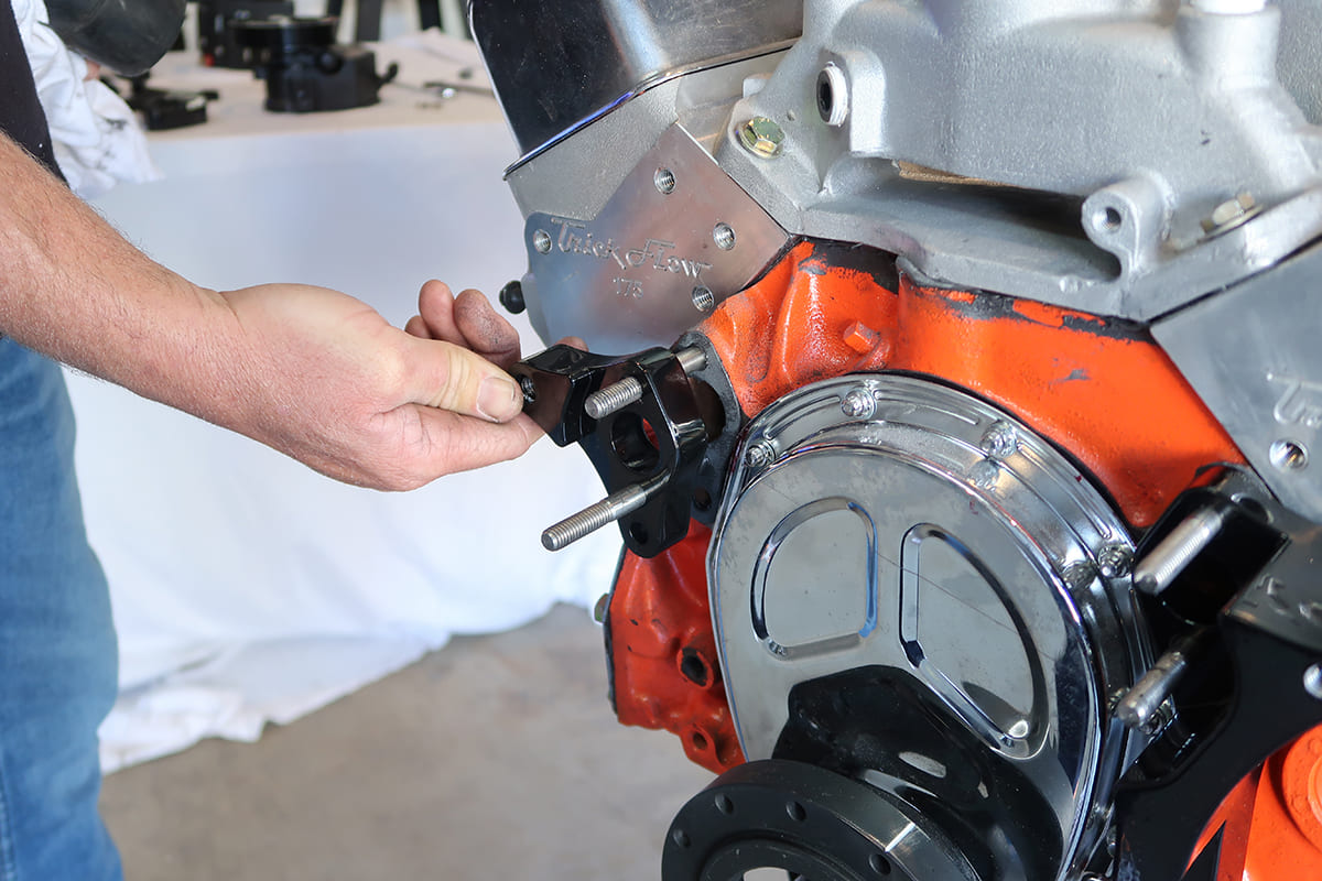
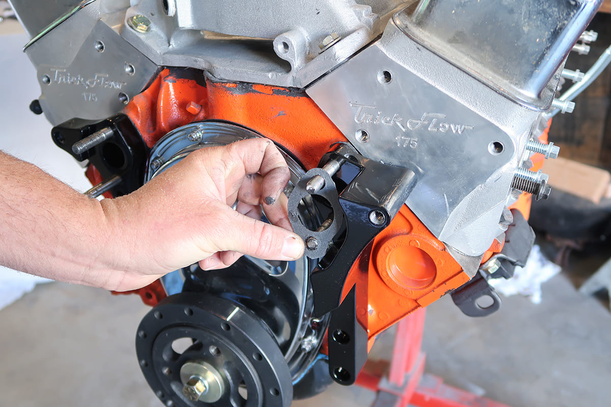
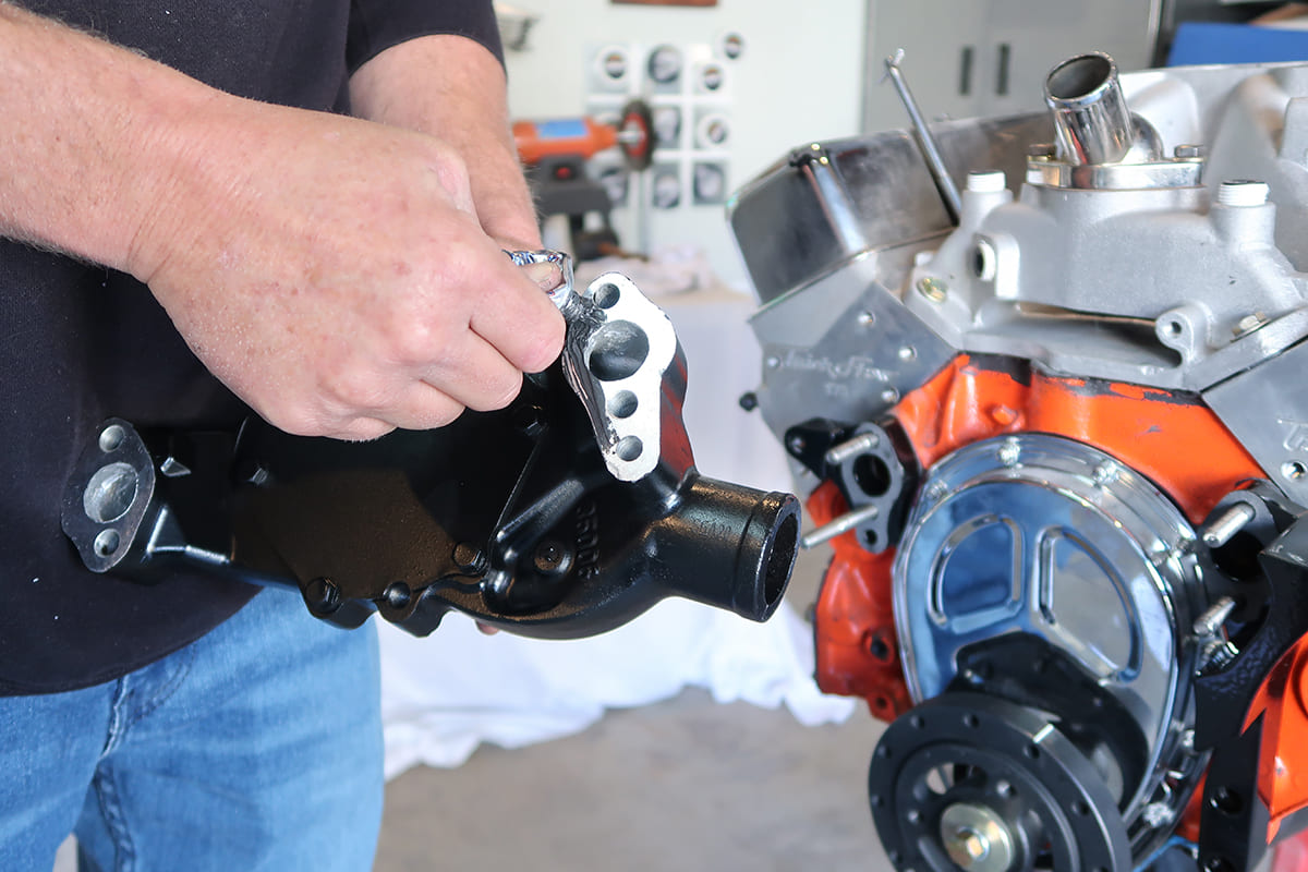
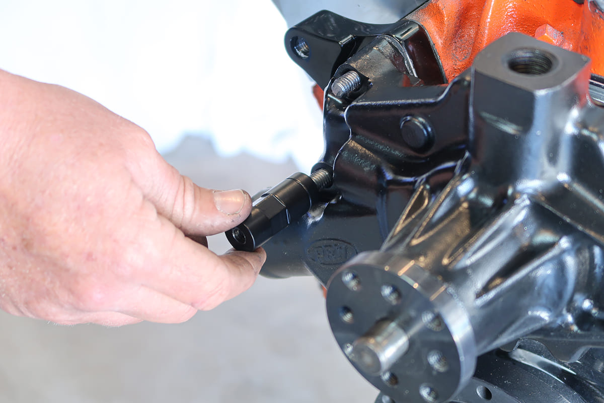
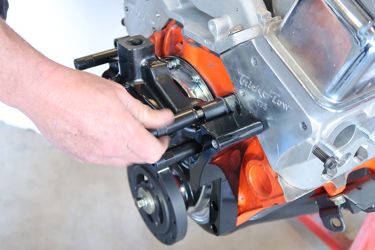
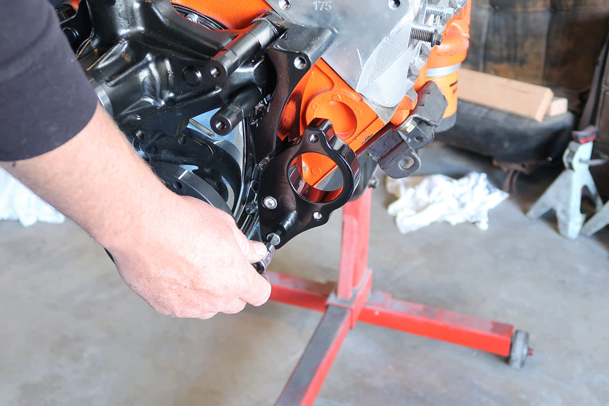
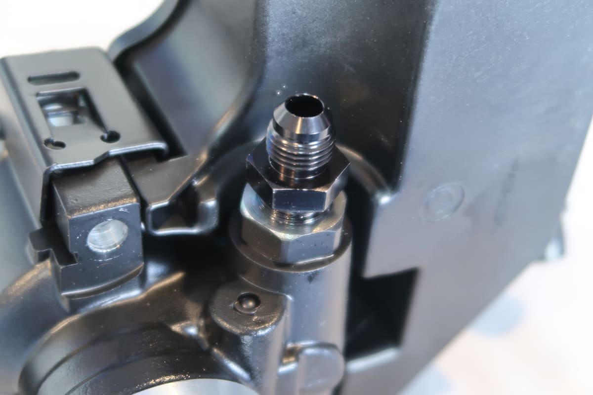
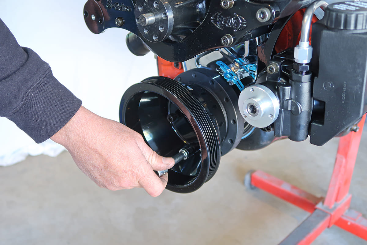
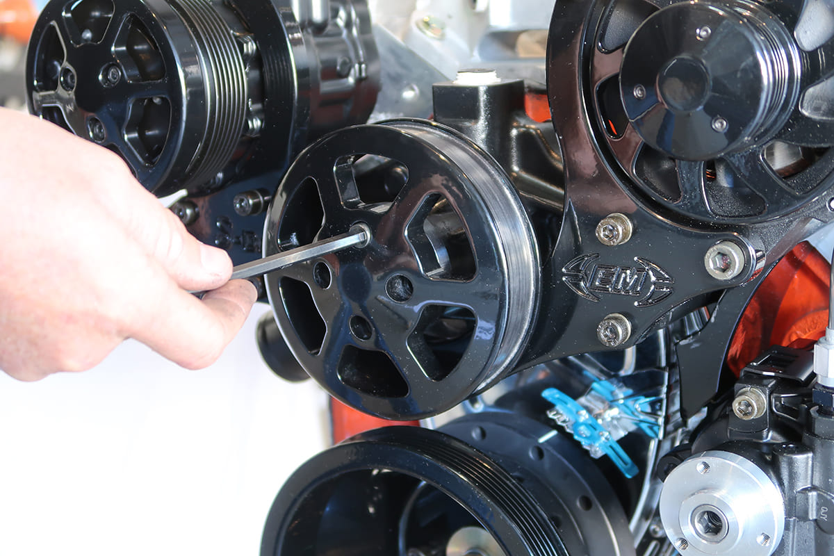
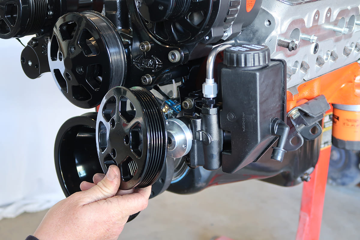
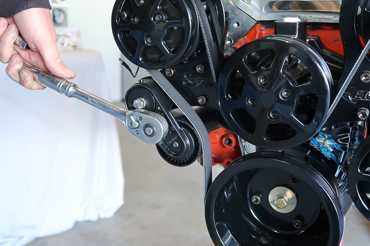
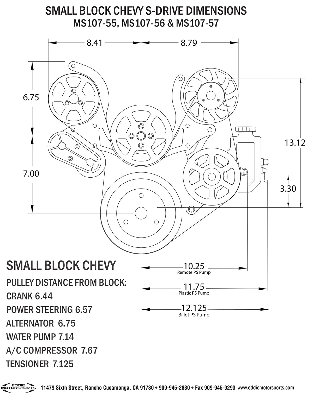
There are four 3/8-inch mounting studs that go into the block. As they penetrate the water jackets they are coated with RTV silicone. By tightening the supplied nuts together, the studs are installed in the block with the longest one in the lower passenger side hole.A thin coat of RTV silicone sealer is applied to the water pump gasket that is installed on the driver’s side of the block.The alternator bracket slides over the driver’s side studs; a pair of socket head screws will secure the bottom of the bracket to the two factory holes in the front of the block.Another water pump gasket is installed on the passenger side. It has an additional small hole in the bottom for the water pump bypass. The purpose is to allow water to circulate when the thermostat is closed without building up excessive pressure in the system.For applications with A/C, the compressor bracket is installed in the air compressor bracket over the passenger side studs followed by a water pump gasket. Again add a thin coat of RTV silicone to both sides of this gasket.Another water pump gasket is installed on the driver’s side. Notice the water pump gaskets on this side only have two small holes for the studs.A bead of sealer is applied to the water pump’s mounting surface. Here, the extra hole for the bypass can be seen.The new water pump slides in place on the studs—the previously installed brackets will now be sandwiched between the pump and the block.After applying anti-seize to the studs the stainless steel stand-offs are installed. The shortest stand-off attaches to the bottom passenger side stud.It’s critical that the stand-offs are installed with the end marked with a groove facing the water pump as the opposite ends have metric threads. At this point the stand-offs are just hand tightened.The power steering bracket can now be installed using the socket head cap screws that go through the lower holes of the alternator bracket and into the block.This is why the stand-offs have to be oriented correctly. They have to accept the four M8 xby 25mm metric socket head cap screws that retain the main bracket. At this stage the fasteners are just snug.For power steering applications S-Drive kits include a GM type II pump with one of two pressure fittings. For GM power steering gear the fitting required supplies 3 to 3.5 gallons of fluid at 1,500 psi. For rack -and- pinion steering, a fitting limiting the pump to 1.5 to 2 gallons per minute at 1,200 psi is used.Three different power steering pump reservoirs are available: —the attached OEM-style plastic tank (shown here), an attached billet aluminum tank, and a remotely mounted aluminum tank in a variety of finishes.The alternator is installed using one M10 byx 80mm socket screw with AN washer through the bottom bolt hole and one M8 byx 25mm socket screw with AN washer through the top hole. To ensure proper grounding, the alternator and A/C compressor should have dedicated ground wires to the block.For secure and vibration- free installation, the A/C compressor attaches to the main bracket with two socket head screws and the previously installed rear bracket with a shoulder bolt. At this point all the stand-offs and the main bracket fasteners are tightened.The crankshaft pulley is installed with three 3/8-24 cap screws and Belleville washers. A thread locking compound should also be attached to the fasteners.When installing the water pump pulley use thread locker on the screws. Keep in mind that with a serpentine belt system the water pump is the reverse rotation style—it spins in the opposite direction of the crankshaft.Again, thread locker is used on the fasteners for the power steering pump pulley. When installing an S-Drive kit pay particular attention to the power steering tank to A-arm clearance. In some cases a remote reservoir will solve clearance issues.To install the belt the tensioner is rotated against the spring. It’s always easier to install the belt around the large crankshaft pulley last.The last step is installing the aluminum tensioner cover. Then it’s time to stand back and appreciate how much cleaner and more compact the engine looks.This diagram shows the how compact the Eddie Motorsports S-Drive systems are as well as showing how the single belt is routed.
We use cookies to ensure that we give you the best experience on our website. If you continue to use this site we will assume that you are happy with it.