


Choosing and Installing The Right Driveline Components
By Ron Ceridono – Photography By the Author & Brian Brennan
It’s been said that “the devil is in the details,” which is another way of saying that many things are more complicated than they appear and overlooking all the factors involved are sure to cause problems. That more or less describes building a hot rod in general and is especially true when choosing and installing drivetrain components.
What Does a Driveshaft Do?
It connects the transmission to the differential. The universal joint accommodates the changes in driveshaft angle as the suspension moves up and down. A slip joint absorbs changes in the distance between the transmission and the differential as the axle housing moves up and down and rotates during acceleration and braking. But while none of that seems all that complicated, the wrong parts and/or improper installation can cause problems ranging from an annoying vibration to total failure that may result in a crashed car and injured occupants.
What Is A U-Joint?
Mark A. Byford P.E. who is an expert on driveline components and design, tells us the universal joint as we know it (technically described as a Cardan-style joint) was designed in 1545 by Gerolamo Cardano and the first working unit was produced by Robert Hooke in 1676, so they’ve been around for a while and the same issues that plagued them then exist today. As Byford describes its operation, “When a Cardan-style joint is operated at an angle, non-uniform motion output is generated, which produces a variety of unwanted vibrations.”
Parting Shot: The California Kid … The Hot Rod and The Movie

What Does A U-Joint Do?

Basically, that means as the U-joint operates at an angle, the ends of the cross where the bearings attach travel in an ellipse. Greg Frick of Inland Empire Driveline adds, “For the joint to rotate through the ellipse it must speed up and slow down twice per revolution. As the angle of operation increases the abruptness of the speed change also increases.” Although it seems driveshaft vibration is inevitable, in reality, with a pair of U-joints, the speed variation of one is canceled out by the other. But regardless of how well this is done, the driveshaft is pulsating twice per revolution all the time. The trick to compensating for this is to have the U-joint angles as close to the same as possible.
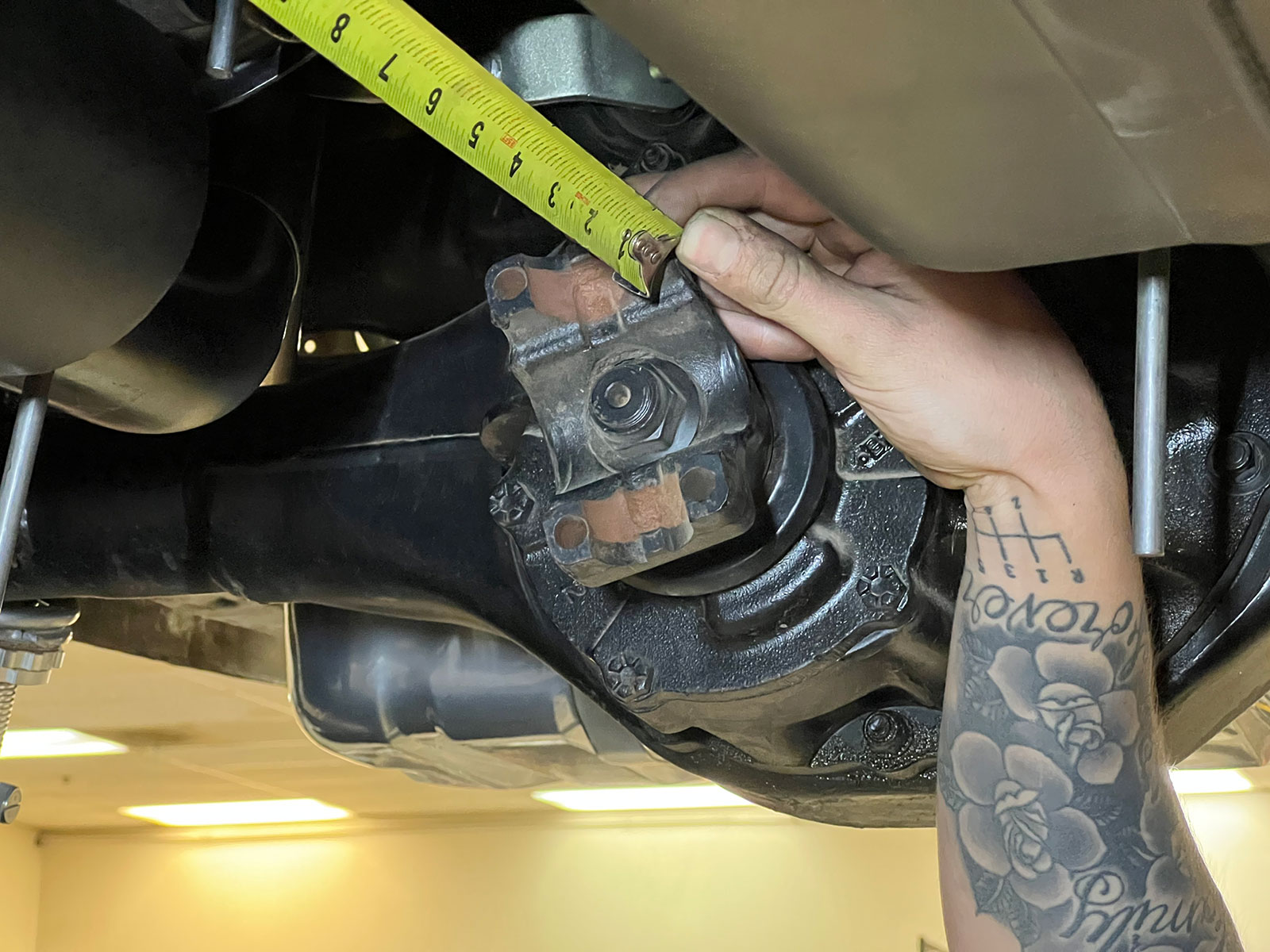
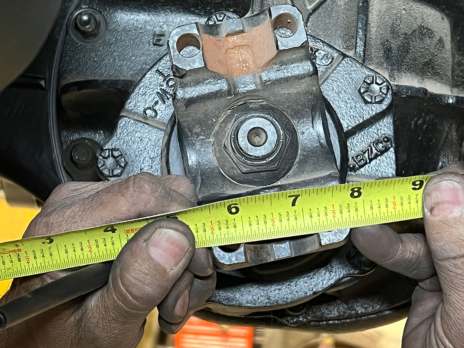
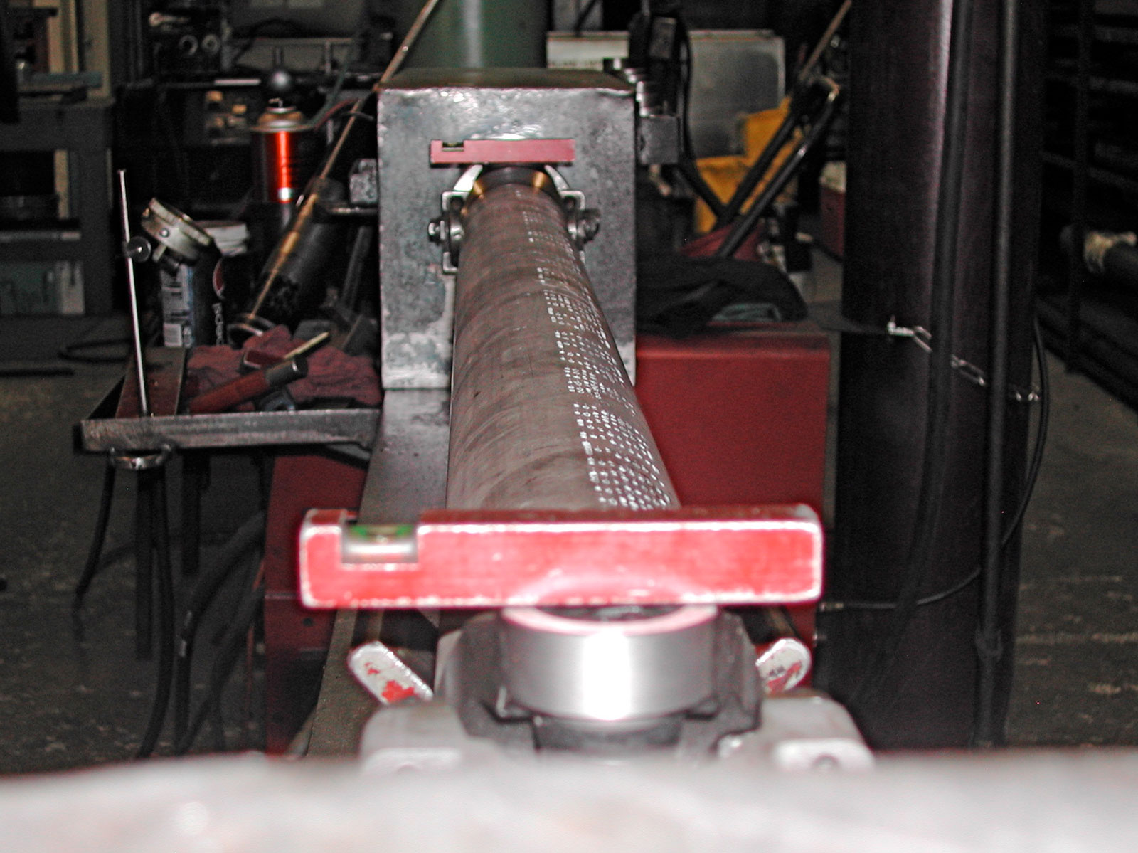
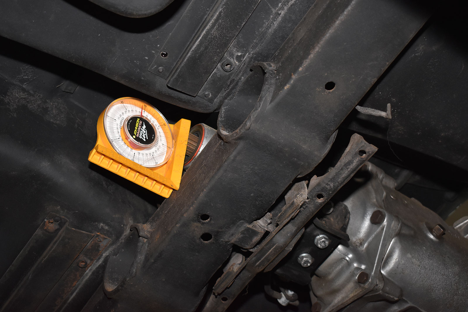
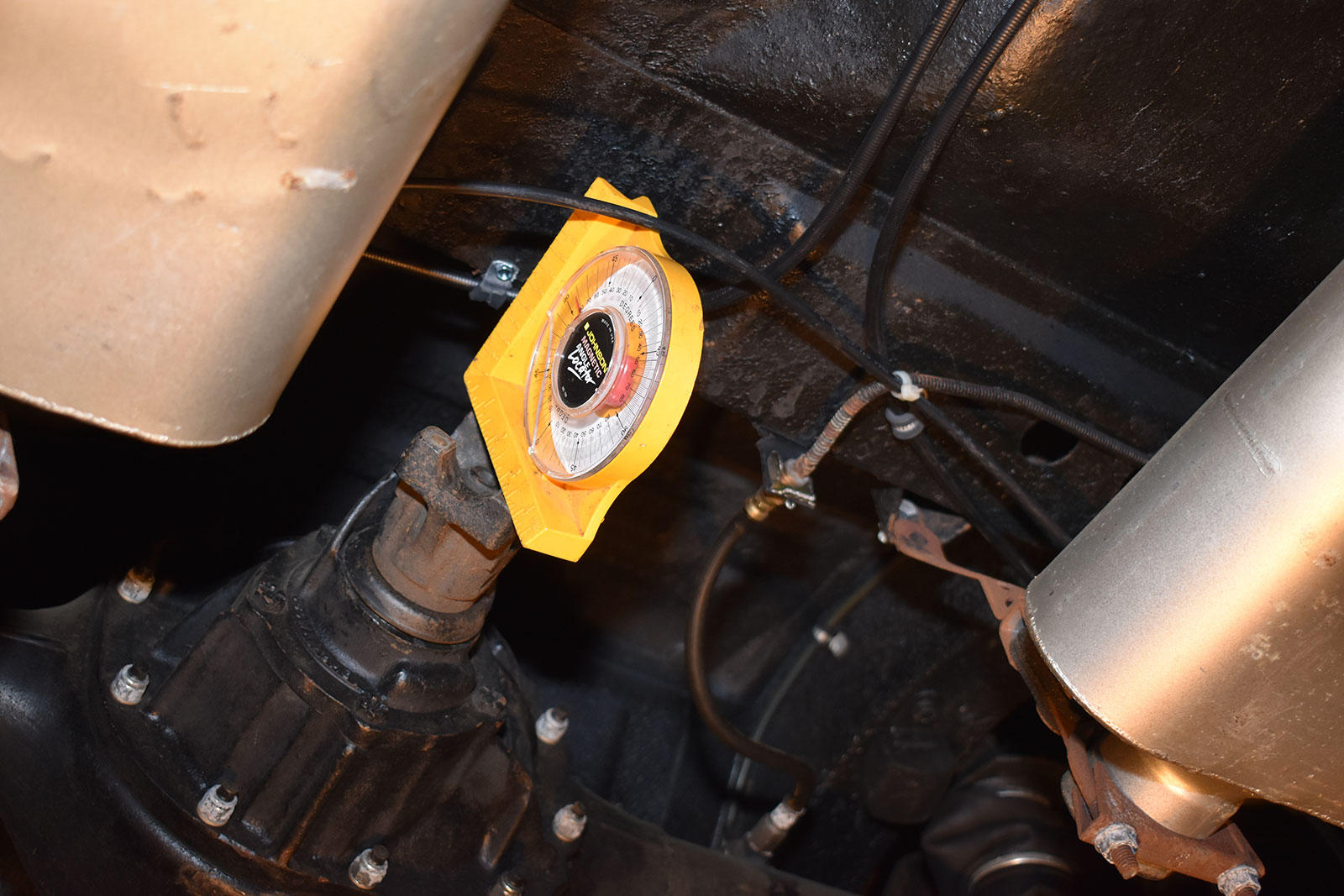
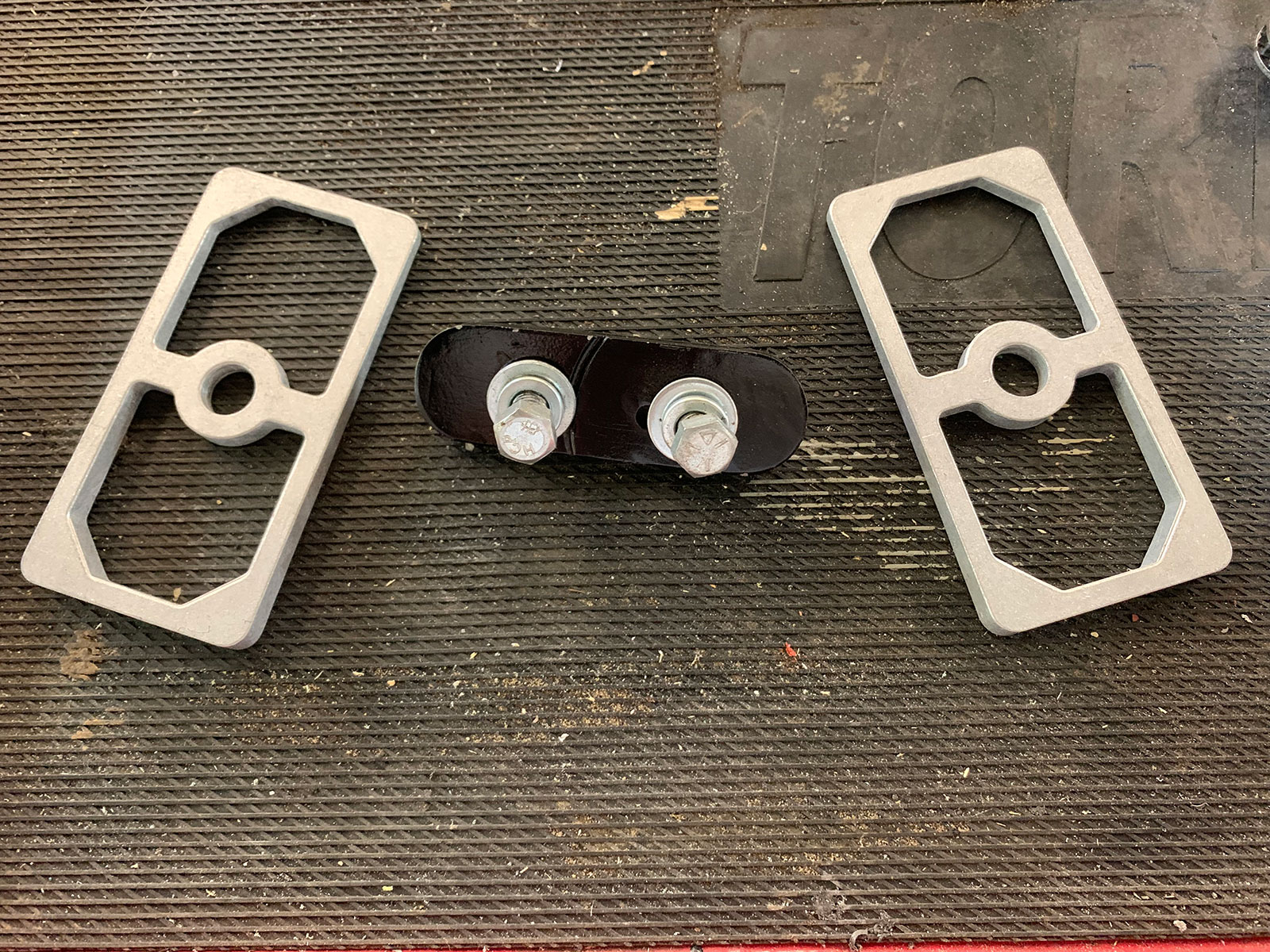
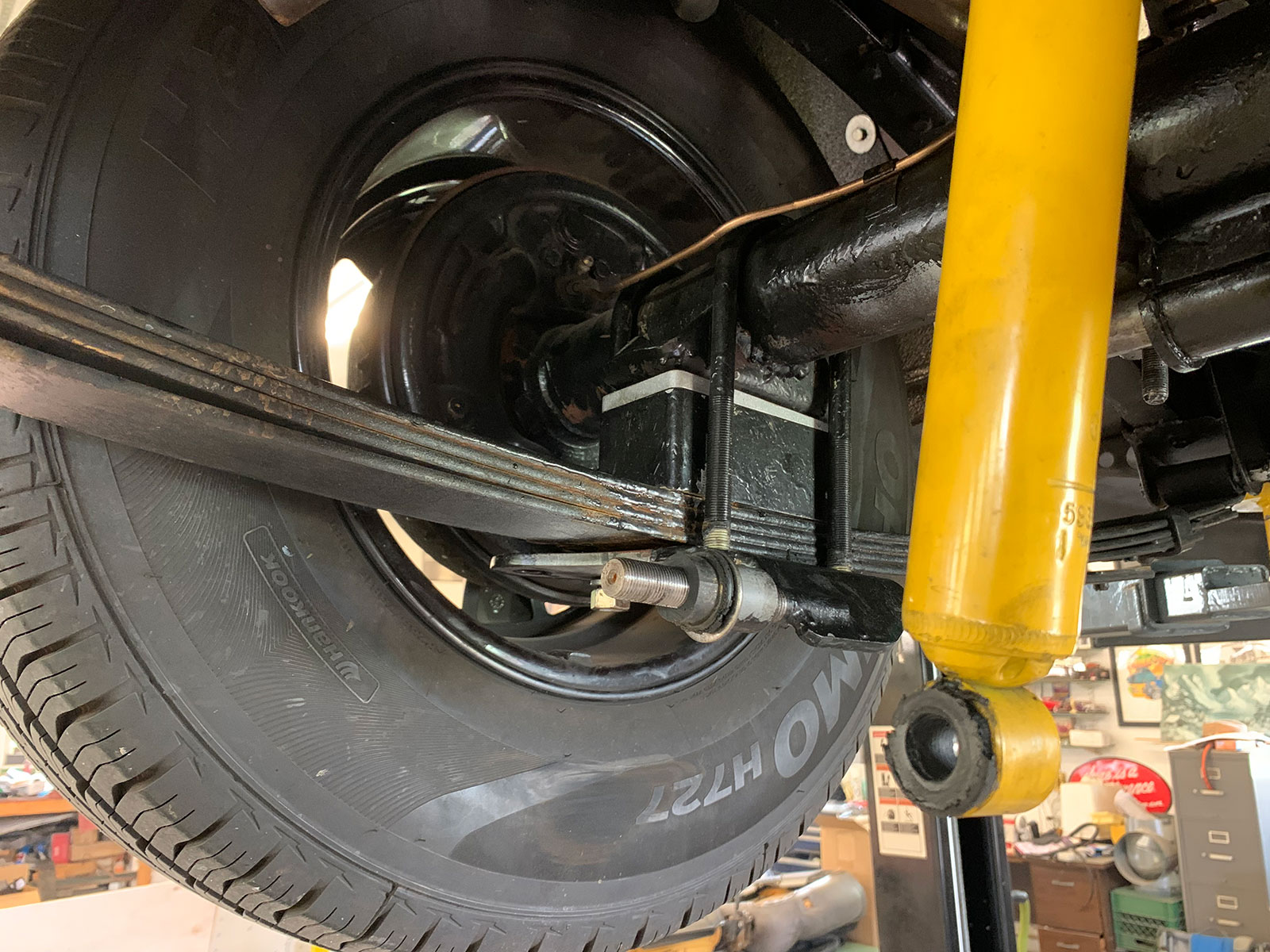
How To Set Driveshaft Angle
First the transmission’s output shaft and the rear end’s pinion shaft should be parallel. That means if the transmission points down 3 degrees, the pinion should point up 3 degrees, which ensures the motion of U-joints cancel each other. Frick points out, “The objective is to add the angles up to equal 0.” That is to say, visualize the output shaft pointing down 3 degrees (which is considered negative) and the pinion pointing up 3 degrees (which is considered positive); those numbers cancel each other out and the working angle is 0. The second factor to consider is the slope of the driveshaft that determines the operating angle of the U-joints. Frick advises that U-joints are designed to have their maximum life operating at 5 degrees or less, however his experience has shown hot rodders will feel angles sharper than 3 degrees.
Another consideration is the angle of the driveshaft horizontally. Some hot rods, such as highboys where the axle housing is visible, will have the axle housing offset to center it under the car for aesthetic reasons. In that case the operating angle must be checked in the horizontal plane as well as the vertical.
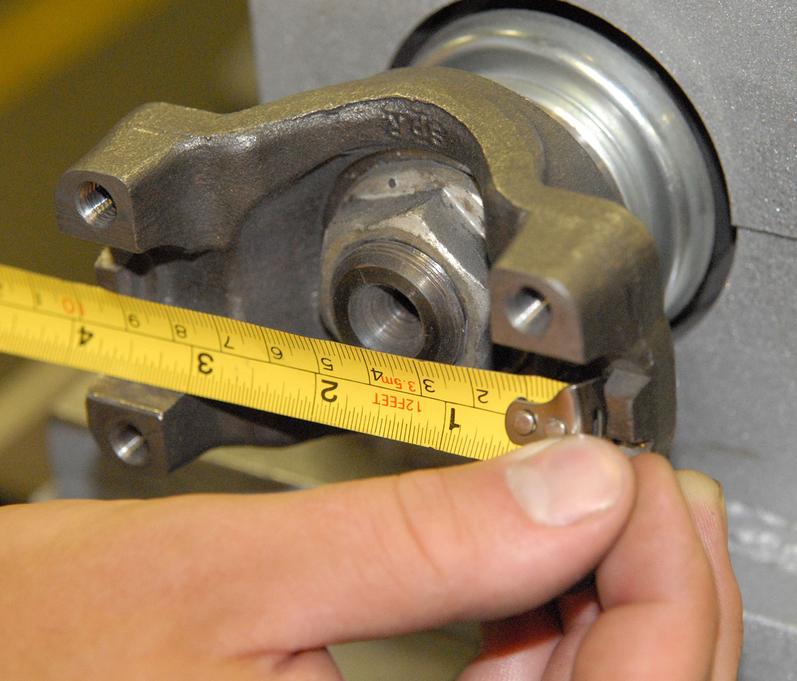
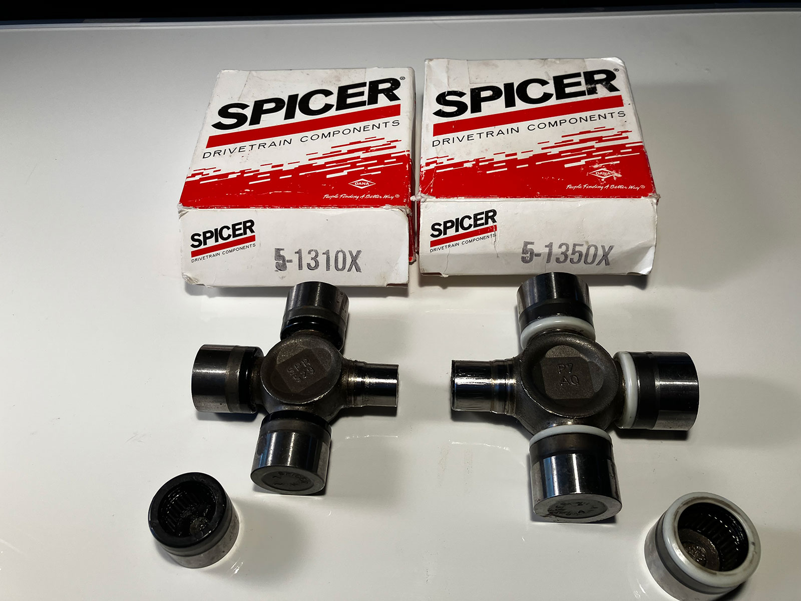
U-Joint Sizes
U-joints are obviously critical driveline components and they come in a variety of sizes. The 1310 series is the most common U-joint for automotive use and is still found on original equipment applications. Caps are 1.062 inches in diameter, width is 3.219 inches. The 1330 series is also very common and used on OE production. Caps are the same outside diameter as the 1310 at 1.0625 inches in diameter but the cross is larger, width is 3.622 inches. For a high-performance upgrade, the 1350 series are often used. The cross is the same width as the 1330 but the bearing caps and trunnions that they pivot on are larger for increased strength. Caps are 1.188 inches in diameter, width is 3.622 inches

Conversion U-Joints
For those applications where the driveshaft and transmission or rear end yokes are different sizes, conversion U-joints are available. These are the common combinations from Spicer and the corresponding part numbers:
1310 ÷ 1350 = Spicer 5 – 460X
1310 ÷ 1330 = Spicer 5 – 134X
1330 ÷ 1350 = Spicer 5 – 648X
Read More: 1935 Chevy Coupe Chassis Prep
Another consideration when selecting U-joints is the difference between those that can be lubricated with a zerk fitting and the sealed type that don’t require maintenance. Frick recommends the sealed style—the improved seals eliminate the loss of lubricant and the lack of passageways to distribute grease improves strength.
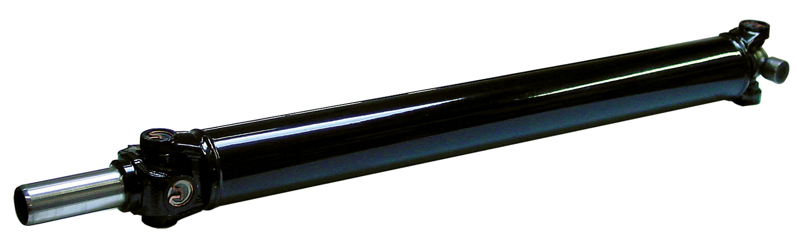
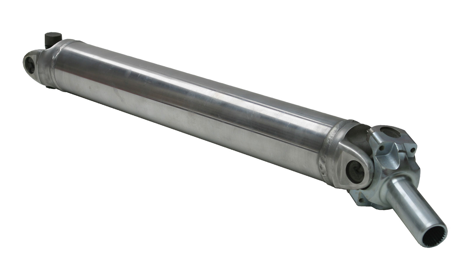
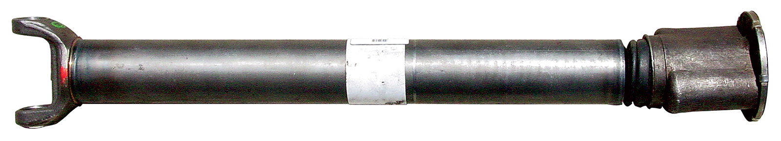
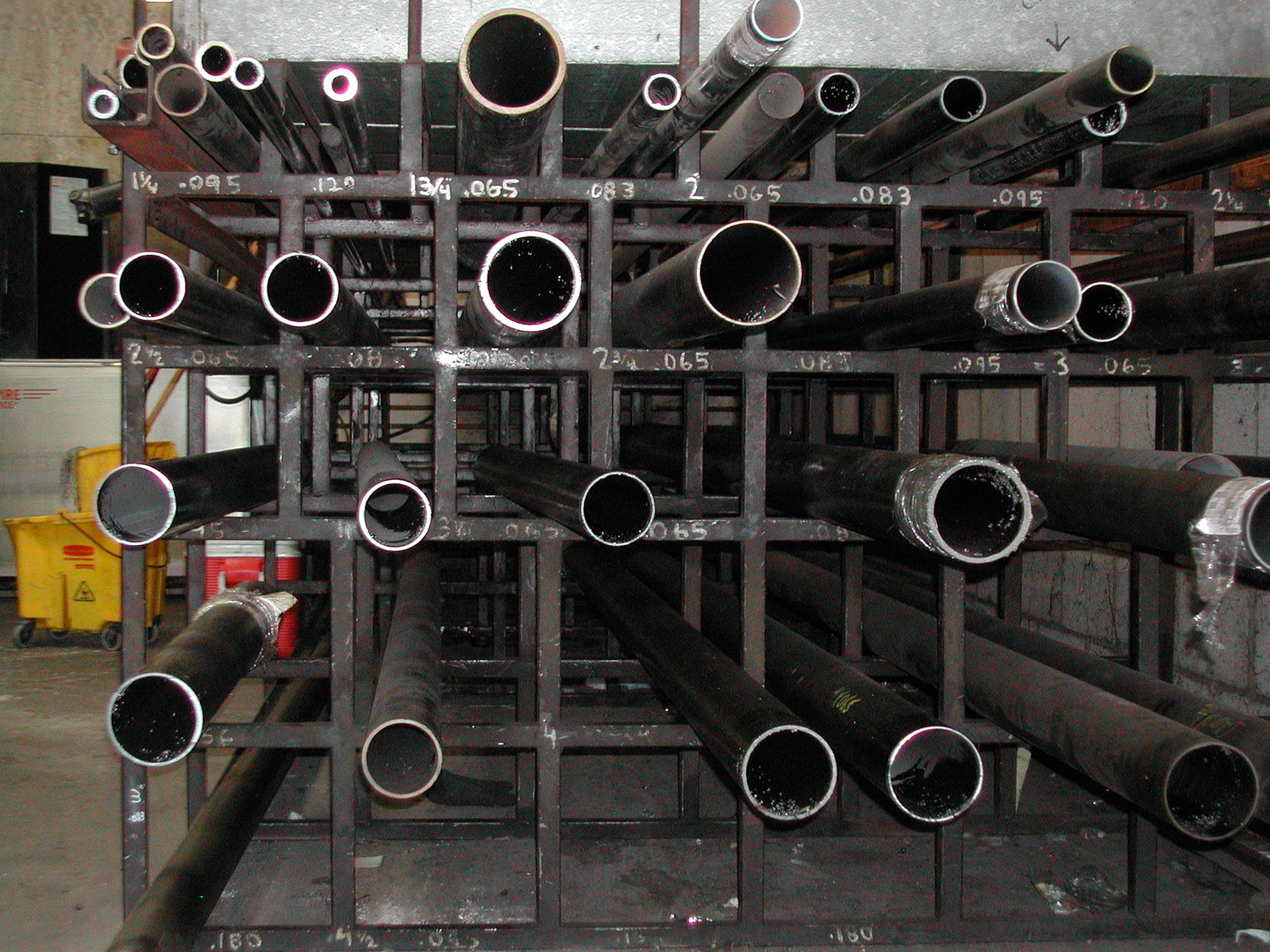
Driveshaft Tube Material
When it comes to driveshafts, they are made from a variety of materials, including, steel, aluminum, carbon fiber, and a hybrid combination of carbon-fiber–wrapped aluminum. Regardless of the material used, an important consideration is something called critical speed.
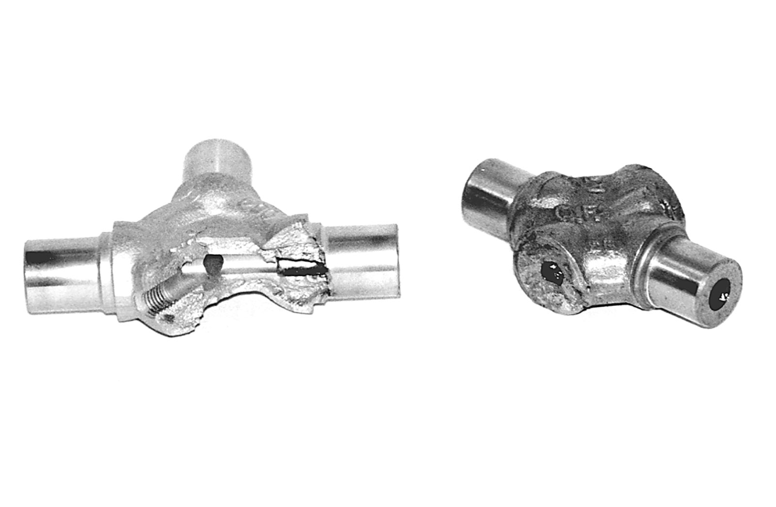
What Is Critical Speed?
Critical speed is the combination of driveshaft diameter, length, and rpm at which it becomes unstable—and that can lead to not only vibration but complete failure. To prevent such problems, Inland Empire Driveline will design a driveshaft with half of critical speed in mind as a built-in safety factor. As an example, they limit the length of a driveshaft with a 3-inch-diameter tube and 0.083-inch wall thickness to 52 inches. A 3-1/2-inch, 0.083 tube is used for 56-inch ’shafts and 4-inch 0.083-tubing is good for up to 62-inch driveshafts.
Two Piece Driveshaft Application
Beyond 62 inches in length Frick recommends using a two-piece shafts with a center support to ward off the “whip” that can be caused by approaching critical speed. Because of the two per revolution pulsating of the driveshaft it will become excited at half the calculated critical speed, resulting in a very mysterious, narrow mile per hour band of vibration.
Overdrive Transmission
Another factor that enters into driveshaft requirements is the transmission used. Frick gives the following example: “In the ’60s, ’70s, and even ’80s there were factory driveshafts that are now considered too long. The Chevelle is a good example. These cars were just fine as built but now run into vibration issues when the engine, or especially the transmission, is changed. Higher torque is available through more gears than the driveline was originally designed for. Overdrive transmissions now slow engine rpm and raise torque demands for the same road speed previously run in direct drive. It is here that the half critical issue is encountered. The driveshaft must now grow from the OEM 3 inches in diameter to 3-1/2 diameter to keep up with the mechanical changes.
Read More: Everything You Need To Know About a Ford 9 Inch Rear End
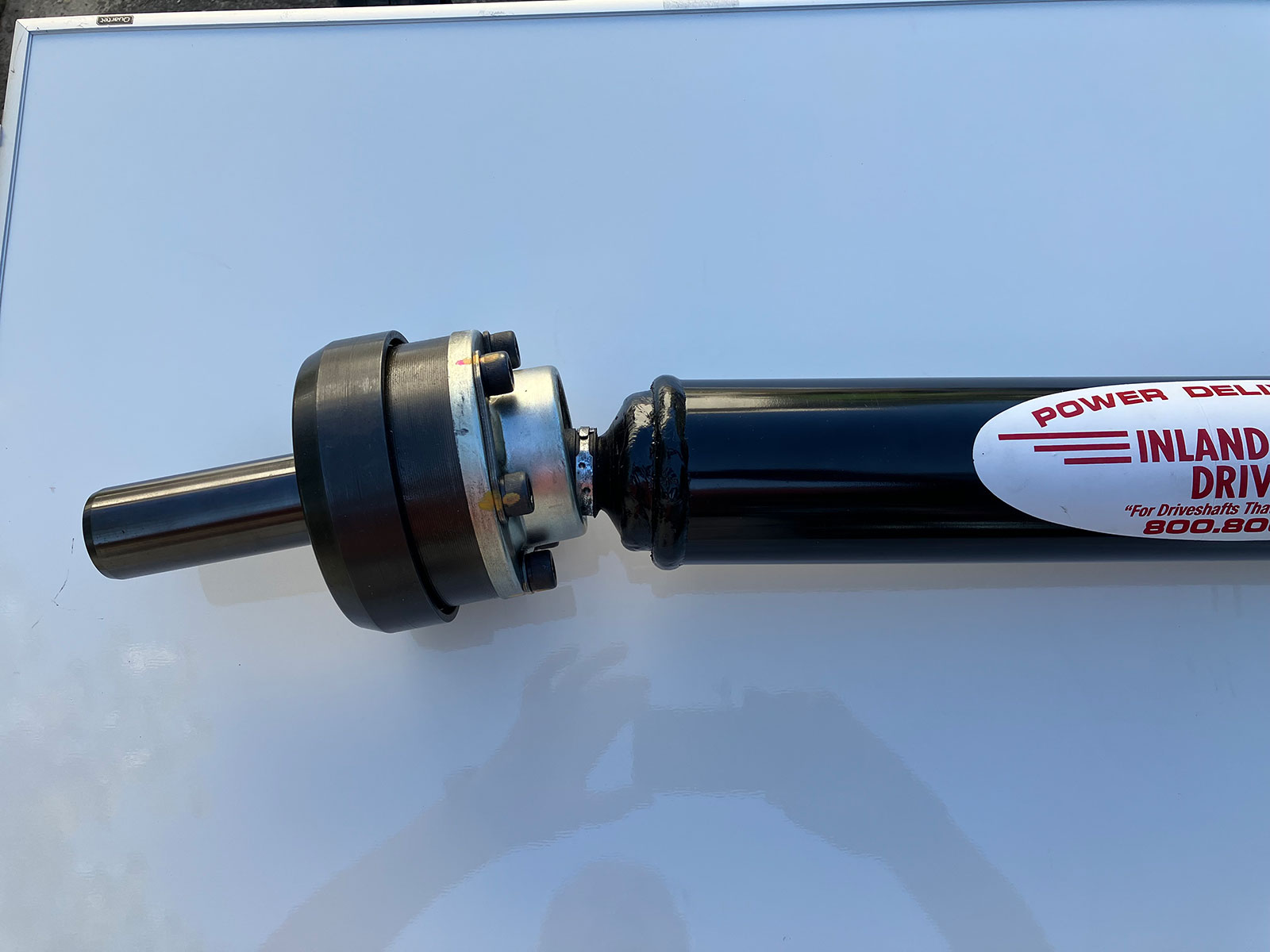
Unfortunately, there are some cases in which there are driveline alignment problems that cannot be easily resolved without extensive modifications to the car’s chassis. However, for every problem there is a solution, and in this situation, Inland Empire Driveline offers the apply named “Solution” driveline that won the prestigious best product award in its category at the 2022 NSRA Street Rod Nationals.
According to Frick, by using a true constant velocity joint the angle problem often found with overdrive transmission installations is solved. The issue generally results from the long transmission’s output shaft being below the pinion yoke, causing the driveshaft to go up toward the rear end. As a result, the angle through the front U-joint grows to unacceptable levels, causing greater pulsating vibrations. Of course, misalignment of the transmission’s output shaft and the pinion that can’t be easily corrected can also be cured with the Solution.
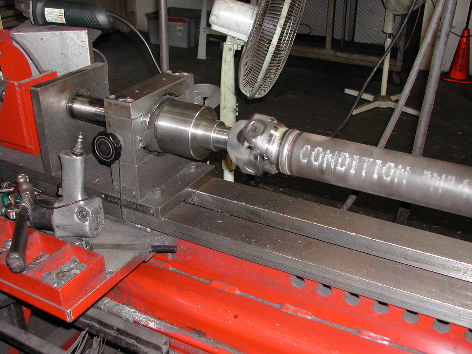
True Constant Velocity Joint Applications
The new Solution is currently available in custom steel shafts for use with 27-spline GM PG, TH350, 700-R4, 4L60, 4L60E, 4L65; the 32-spline TH400, 4L80, 4L85; and Gear Vendors overdrive units. Also available are the 31-spline Ford C-6 and Top Loader, and TREMEC TKO, TKX, and Magnum transmissions.
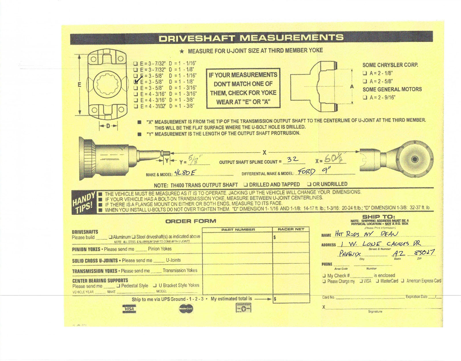
While drivelines are more complicated than they seem, ordering one from Inland Empire Driveline is as simple as it can be. Fill out their order form with the required measurements, then follow our installation recommendations for the various angles involved and those in the Inland Empire Driveline Powertrain SetUp Guide, and a custom driveline will be delivered to your door. That’s the way to eliminate the devil in the details. MR

Sources
Inland Empire Driveline Service
(800) 800-0109
iedls.com
Speedway Motors
(800) 979-0122
speedwaymotors.com


