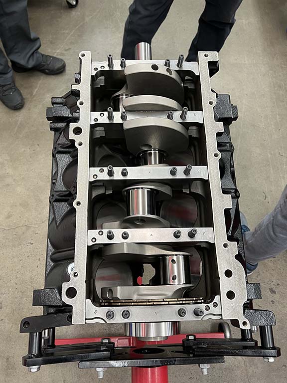
Thorough block inspection is paramount to a successful performance engine build, and Kyle Martelli and the team at American Heritage Performance’s (AHP) attention to detail will no doubt show through when we put our LS engine through its paces on AHP’s dyno. But before that can happen, we need to continue with the assembly process, starting with the rotating assembly.
We wrapped up the last story with a clean and inspected iron block and the Summit Racing 3.622-inch stroked crank in place. The next step is to prep our rotating assembly, once again inspecting all tolerances.
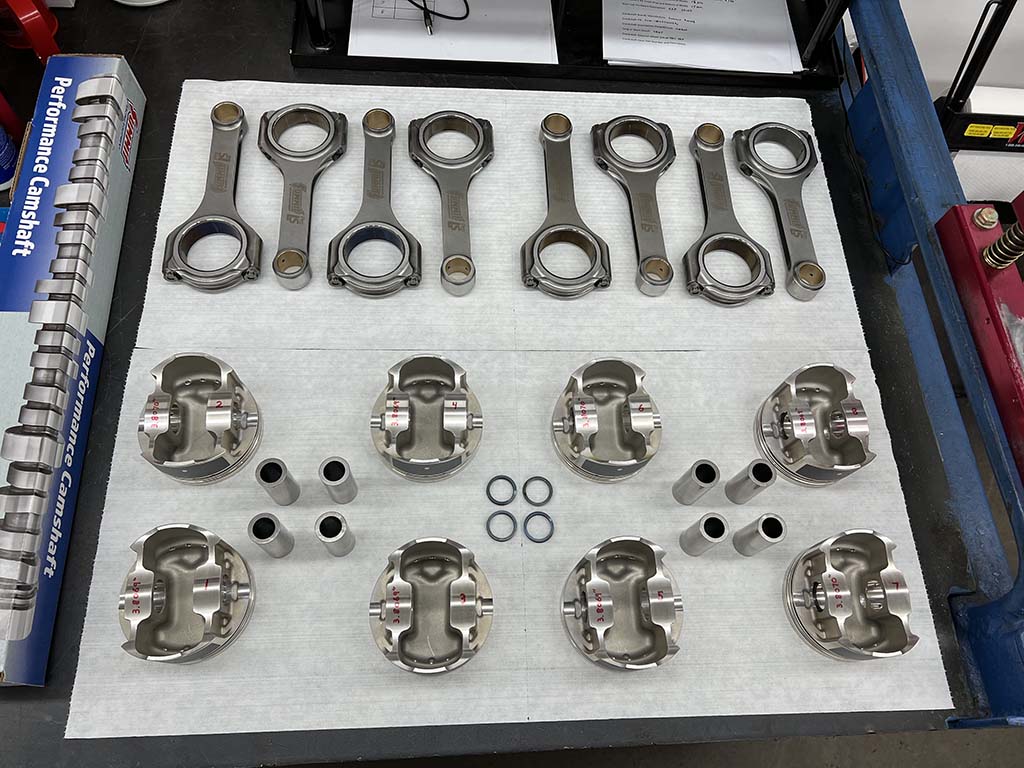
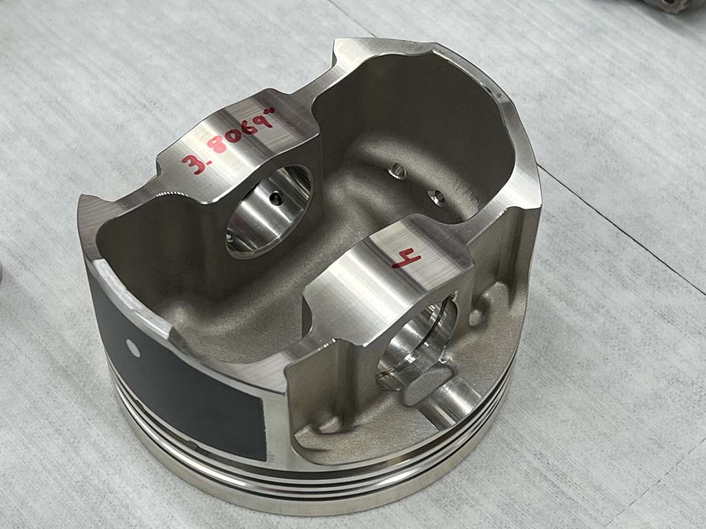
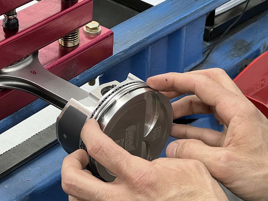
To continue with our Summit build, it should come as no surprise that we chose to use their LS Pro line of products for nearly all the moving parts in our motor. Starting with their 6.125-inch H-beam connecting rods and concluding with a set of their forged 2618 alloy pistons, the top end of our LS is a complete assembly of Summit Racing LS Pro parts. Like the crankshaft installation, Martelli inspected all the components, noted the results, and compared them to the specs provided by Summit and the bearing manufacturer. Pleased with the results, Martelli proceeded to file the ring pack to spec before assembling the piston/rod assembly. From there, using an ARP piston installation tool, Martelli dropped each slug pack into their respective cylinder, torquing every rod cap to spec via ARP 2000 rod bolts.
For our 330ci build, Martelli and the crew at American Heritage Performance (AHP) chose components from Summit Racing’s Pro LS line. This includes a set of pistons (PN SUM-2999273810-7) forged from premium 2618 alloy, durable Chromium Steel wristpins, and Spirolock retainers.
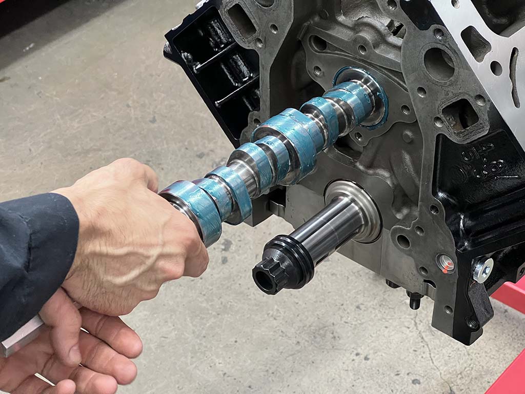
With the rotating assembly complete, Martelli then turned his attention to the installation of the camshaft. When it came to camshaft selection, we went with recommendations from both the AHP and Summit Racing teams, resulting with another selection from the Summit LS Pro line. Featuring 222 degrees of duration on the intake side and 234 degrees on the exhaust side at 0.050-inch lift, the resulting hydraulic roller tappet camshaft should provide plenty of low-end grunt, a good idle lope, and plenty of top-end power.
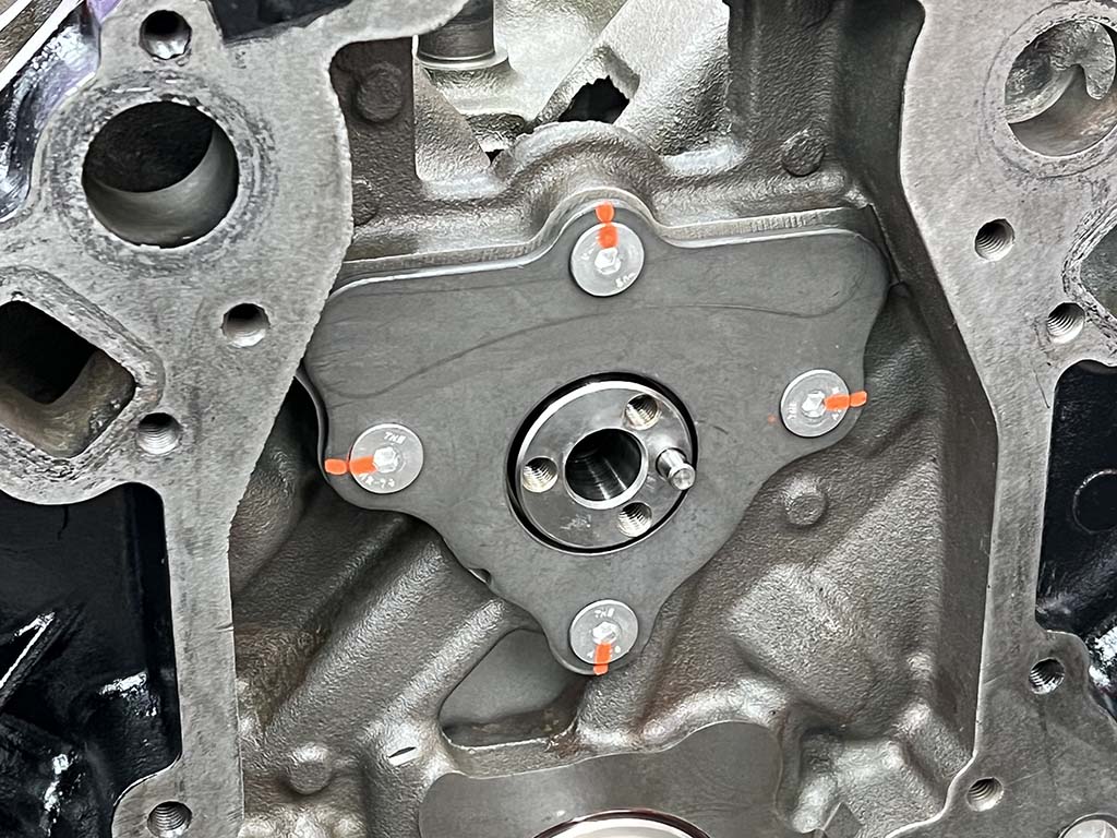
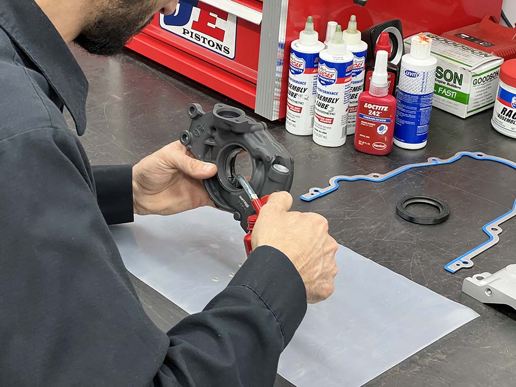
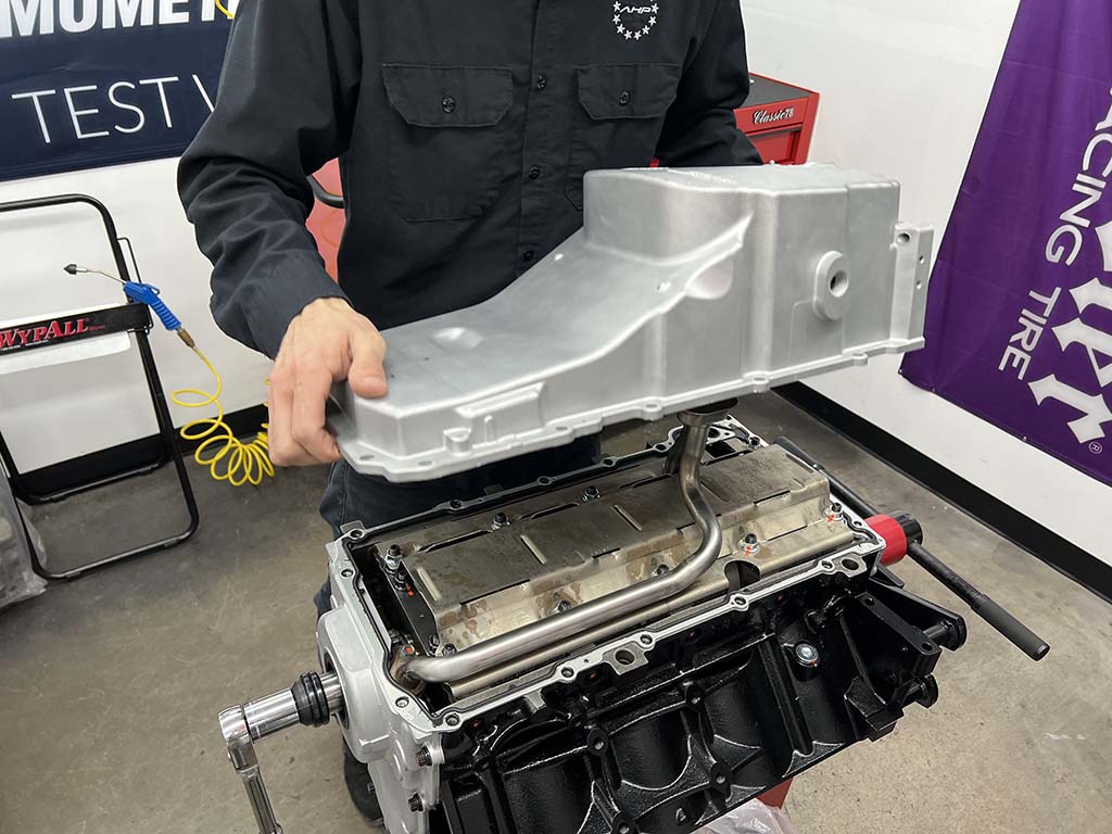
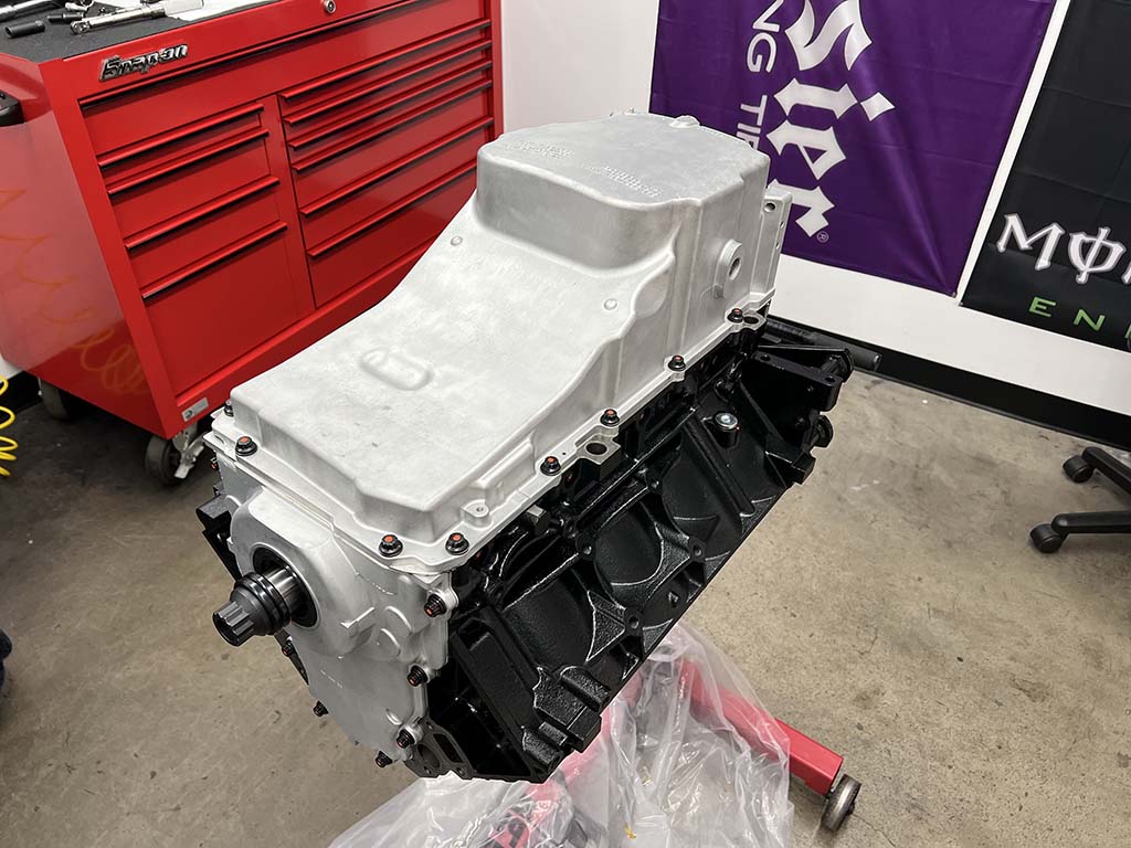
From there, Martelli installed the timing chain components and the high-volume oil pump. Front and rear covers were then installed, followed by a stock oil pan, effectively sealing up the bottom end of our short-block build.
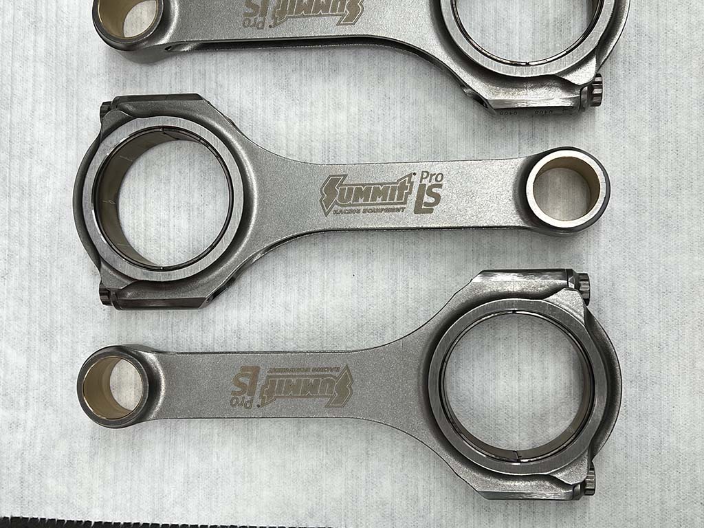
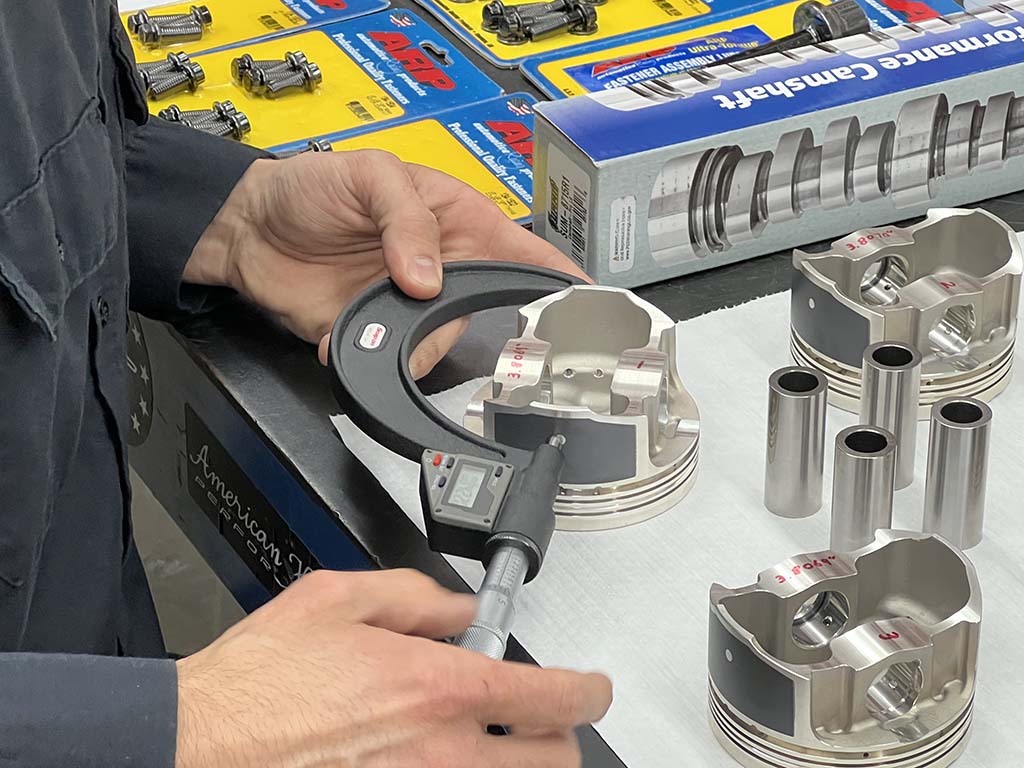
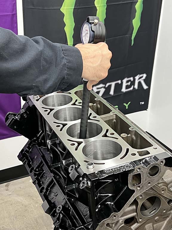
To mate the pistons to the crank, 4340 Forged Steel Pro LS H-beam connecting rods (PN SUM-LS6125927) from Summit will be used. Designed for up to 5,000 ft/min average piston speed, these durable rods feature a 6.125-inch length and will clear most camshafts up to a 4.250-inch stroke. Twelve-point ARP 2000 rod bolts come standard to ensure the rotating assembly remains fixed to the crankshaft.Having previously balanced the rotating assembly there are still a few inspections that need to be made before Martelli begins assembly. First, each piston is carefully measured and its diameter noted.
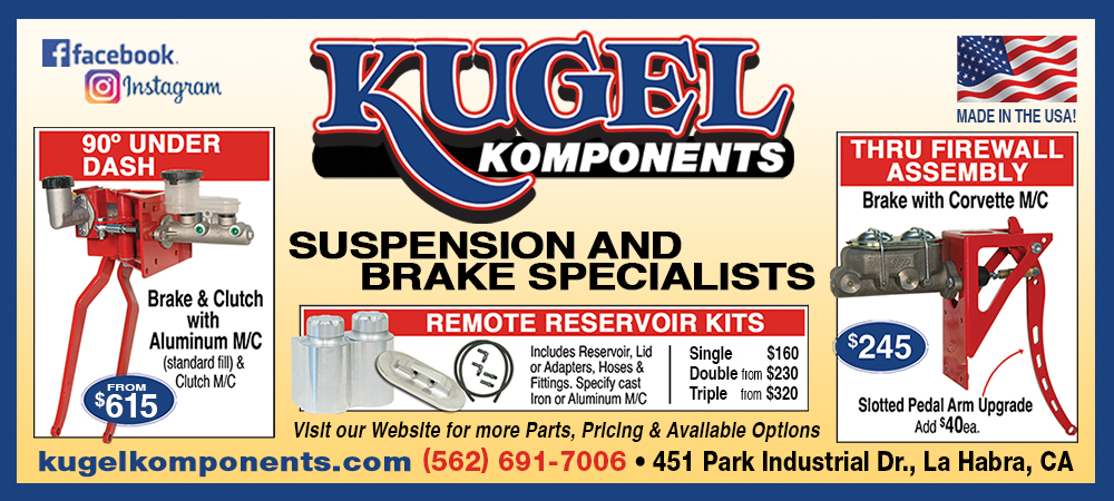
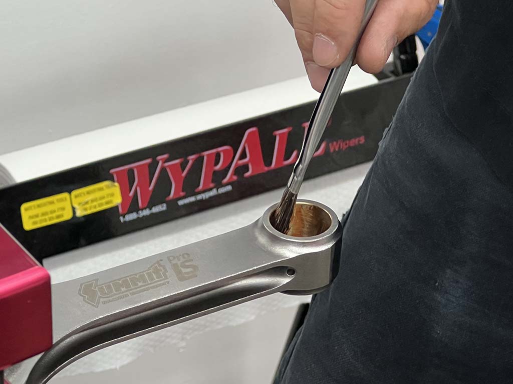
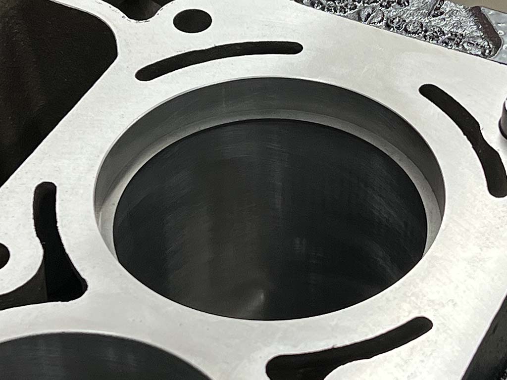
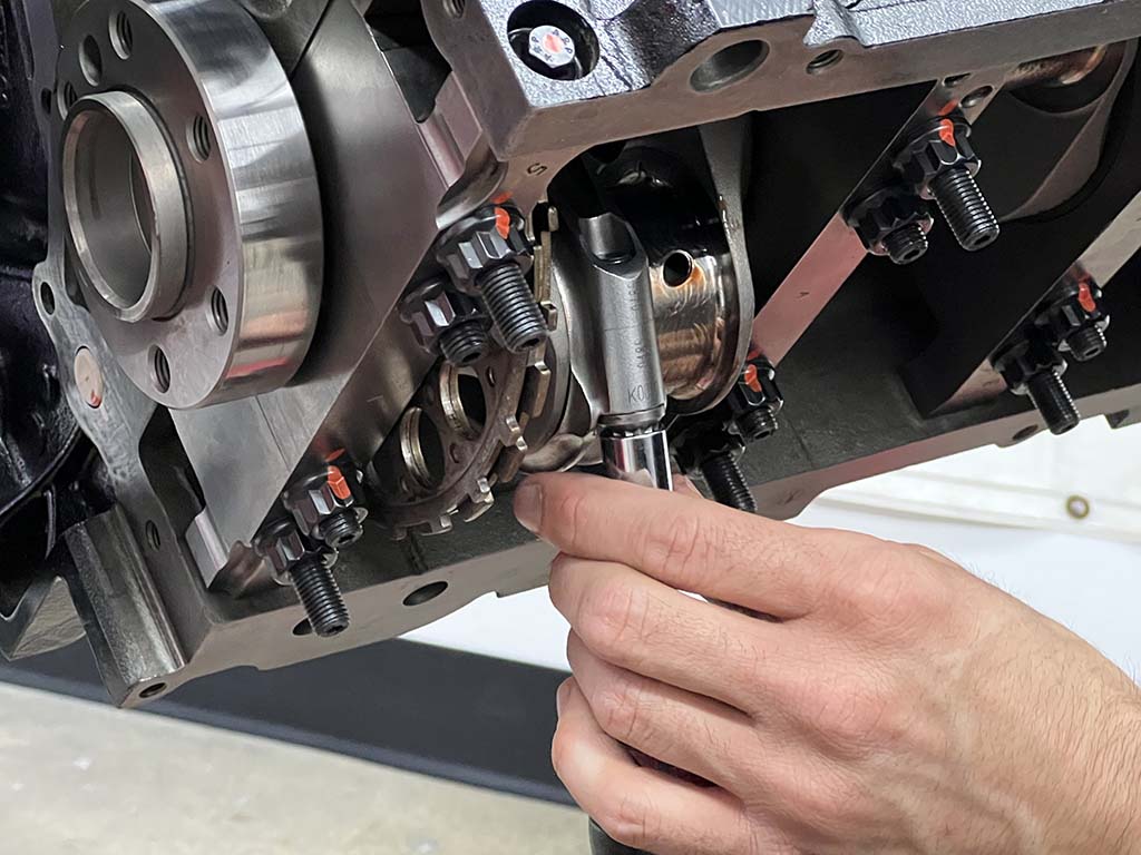
Next, Martelli uses a dial bore gauge to measure each cylinder’s bore. Those specs are then noted and compared to the piston measurements. The pistons are then matched to the most appropriate cylinder to maintain a consistent piston-to-wall clearance around 0.0040 inches for all cylinders.Next, Martelli measures the big end of each connecting rod with the bearings installed and the ARP 2000 rod bolts torqued to spec and compares this number with the diameter of each connecting rod journal on the crankshaft. This provides Martelli with the connecting rod bearing clearances (0.0027 inches).With inspection of the rotating package complete, Martelli begins assembly. First, assembly lube is applied to the con rod’s small end, piston pin, and piston pin bore.
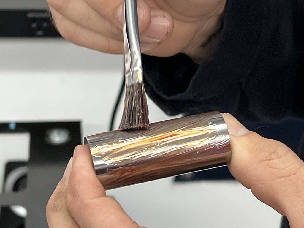
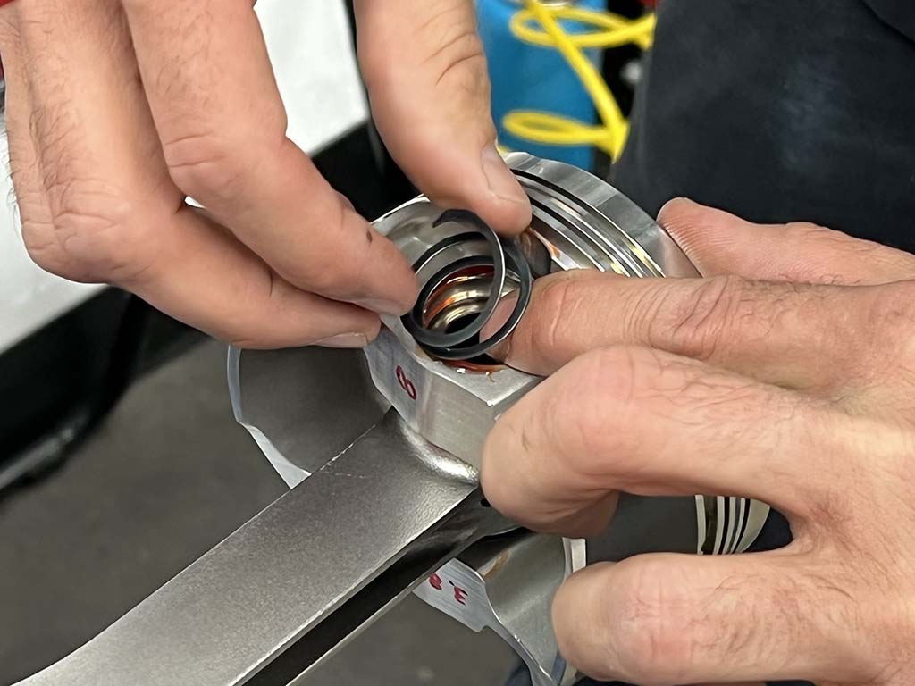
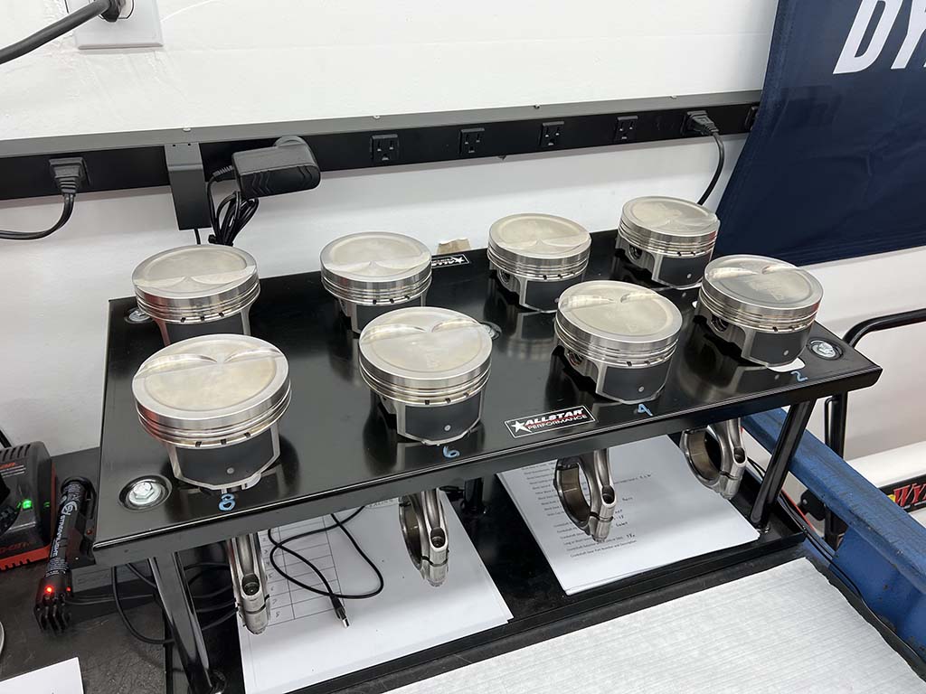
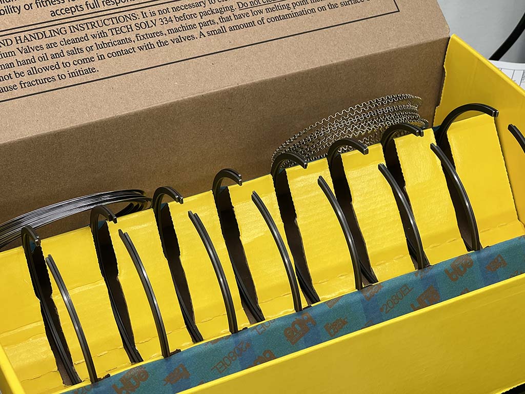
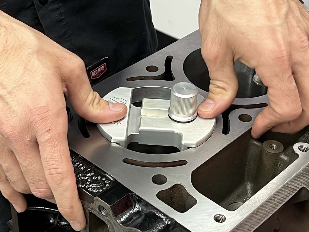
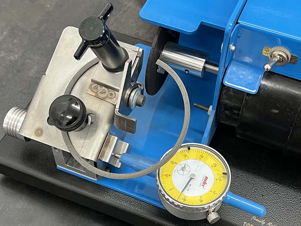
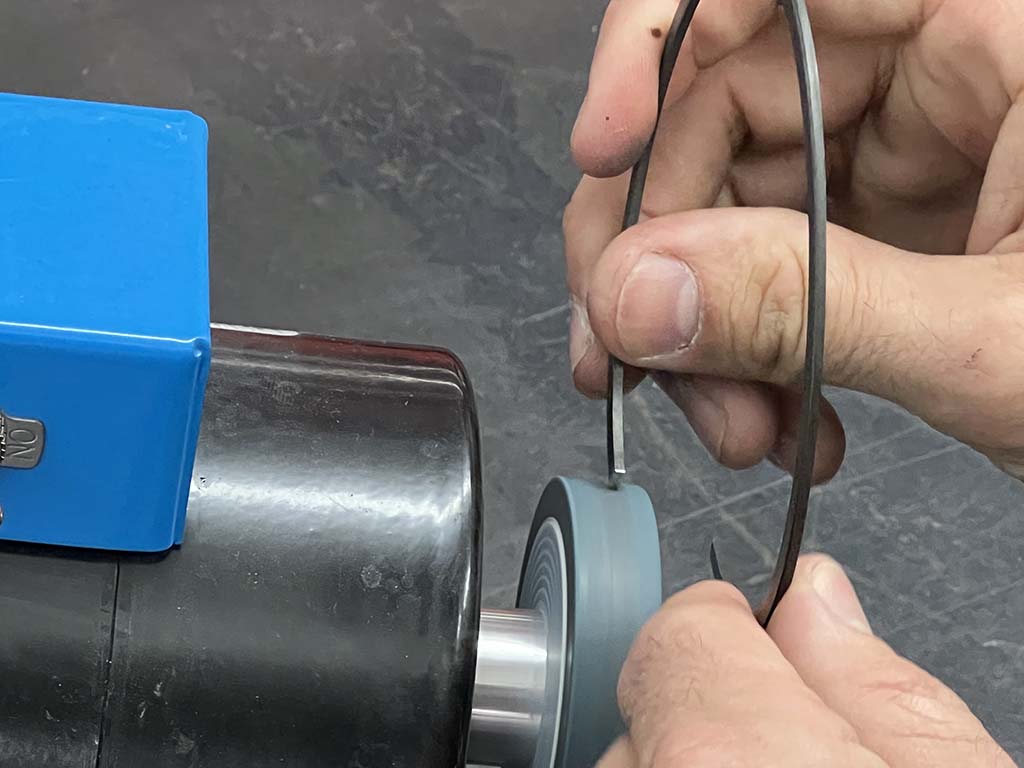
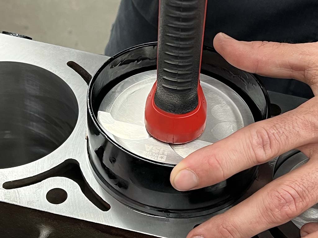
Spirolock pin retainers are used to hold the assembly together. Martelli slightly separates the spiral wire before carefully rotating it into position.All eight assemblies are placed in a fixture according to their respective location in the engine for easy assembly.A set of Hastings steel performance piston rings (Summit PN SM8531035) will be used to control the oil and compression, but the two top compression rings need to be filed to fit each cylinder before assembly can begin.Each ring needs to be placed squarely in the bore before the ring endgap can be measured. A Summit Piston Ring Squaring Tool (PN SME-906002) is a great way to accomplish this.
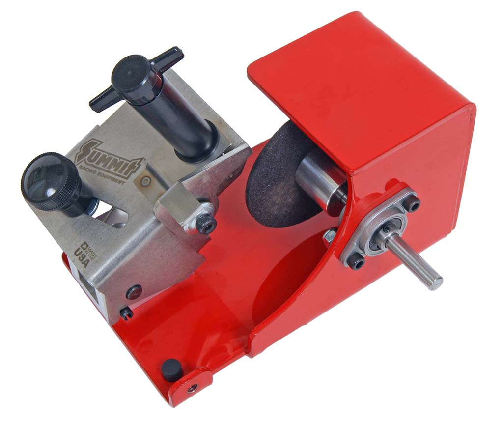
Out of the box, the ring endgap is very small and needs to be filed to fit the cylinder bore using a piston ring filer like this one from Summit Racing (PN SUM-970011).
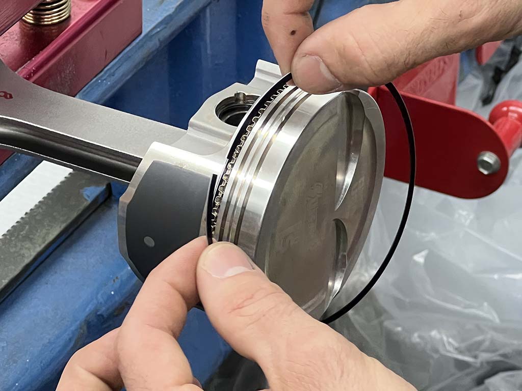
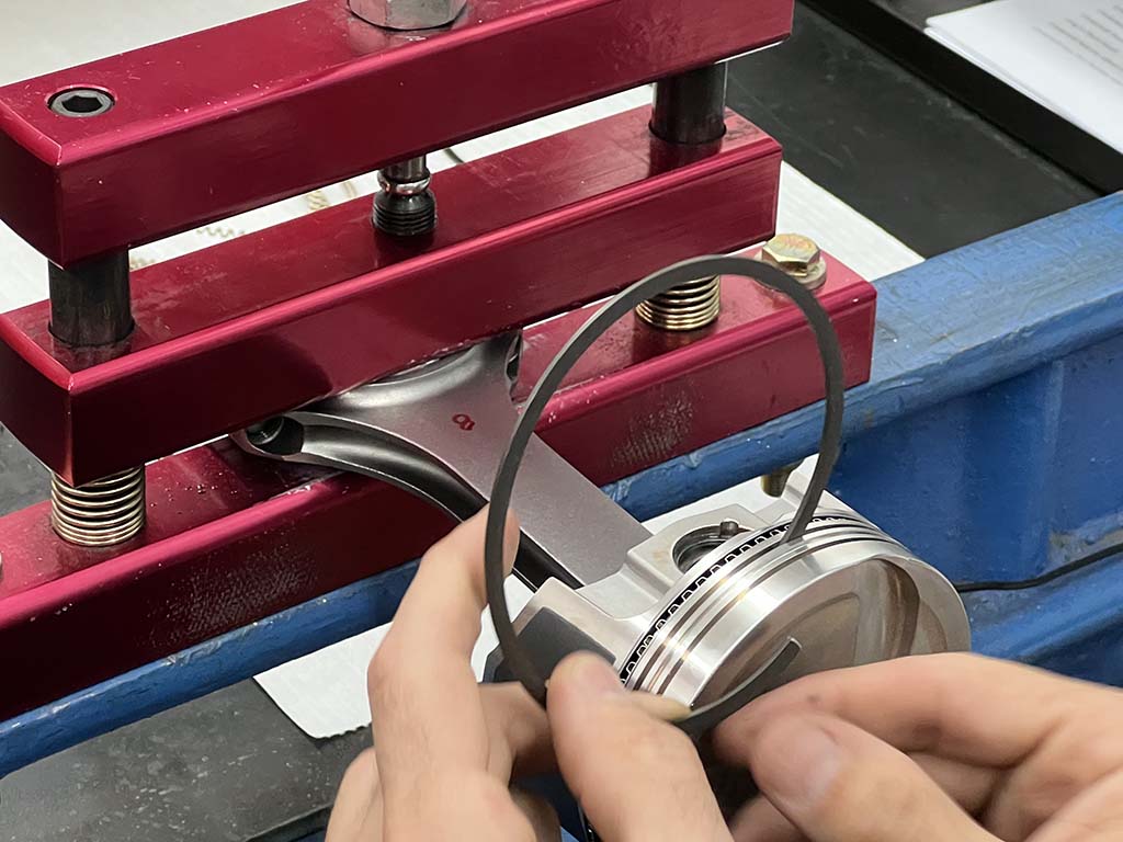
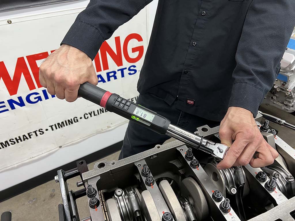
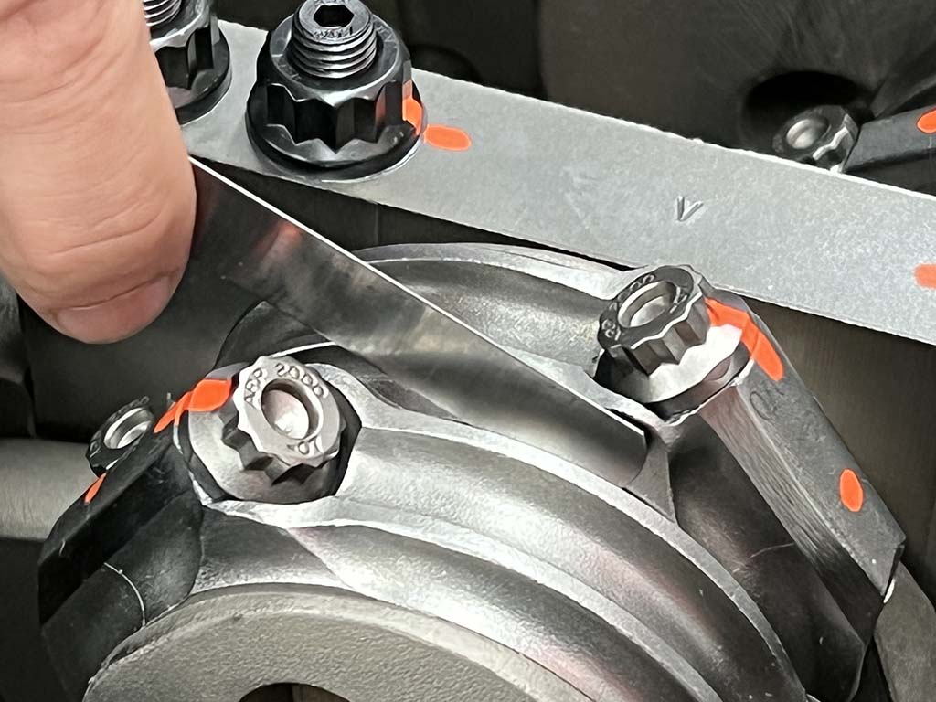
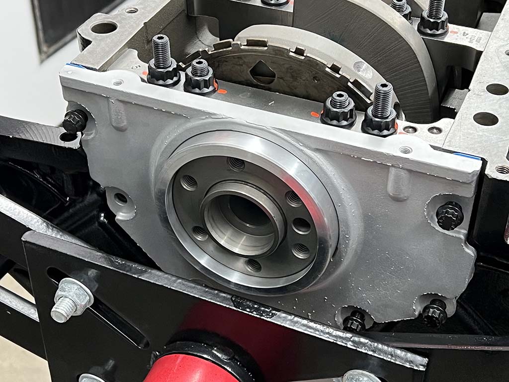
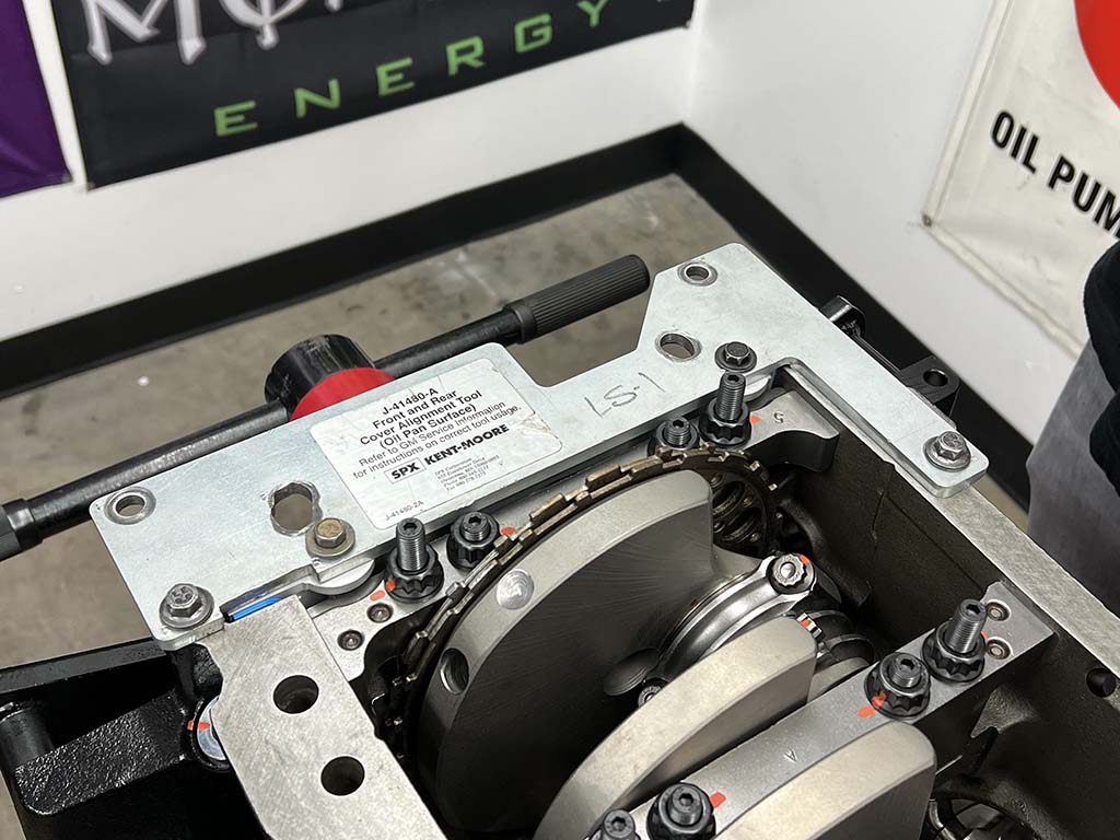
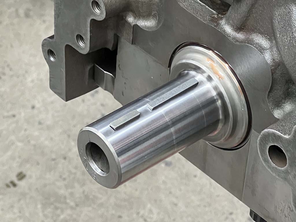
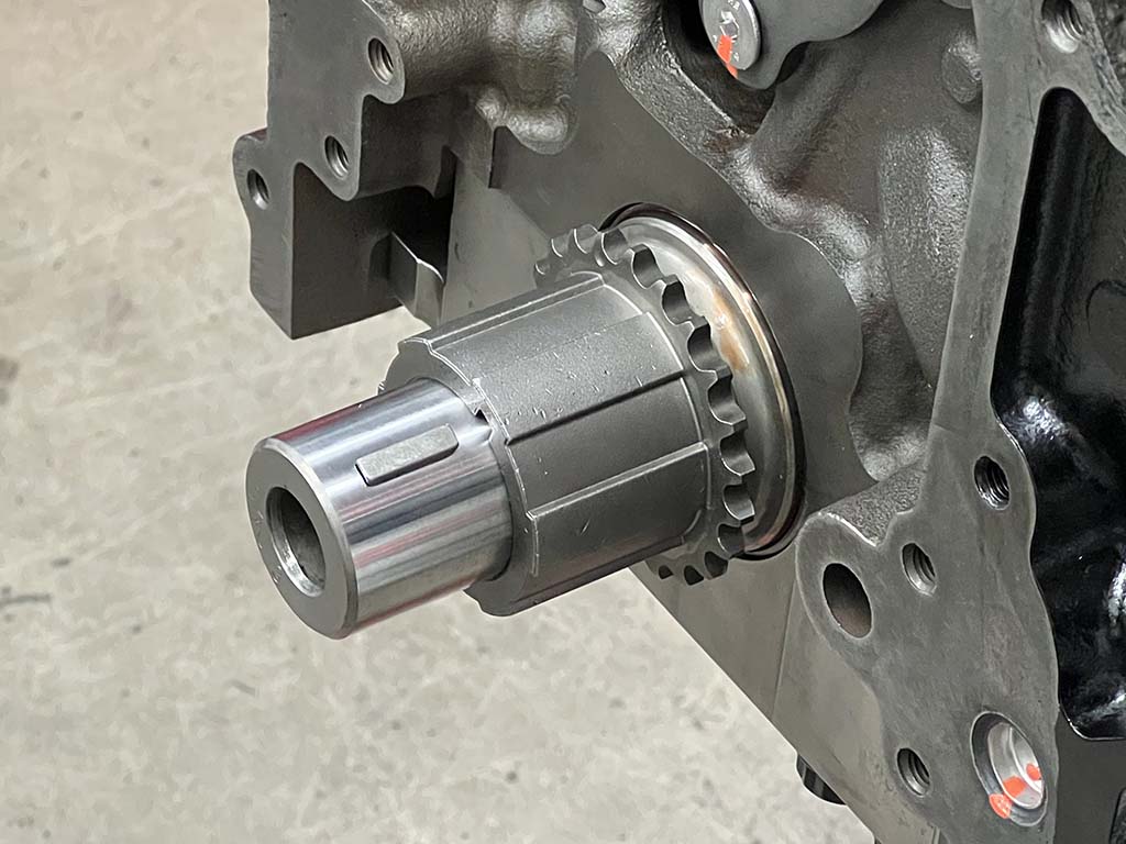
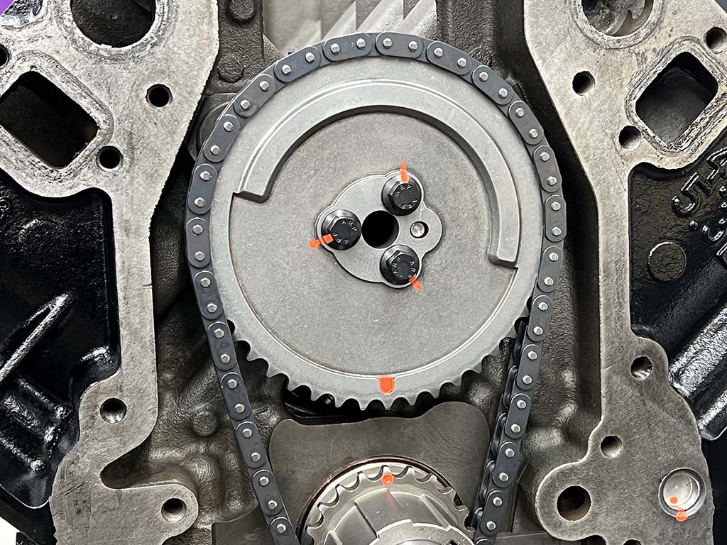
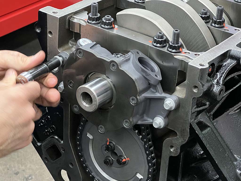
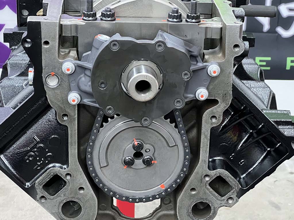
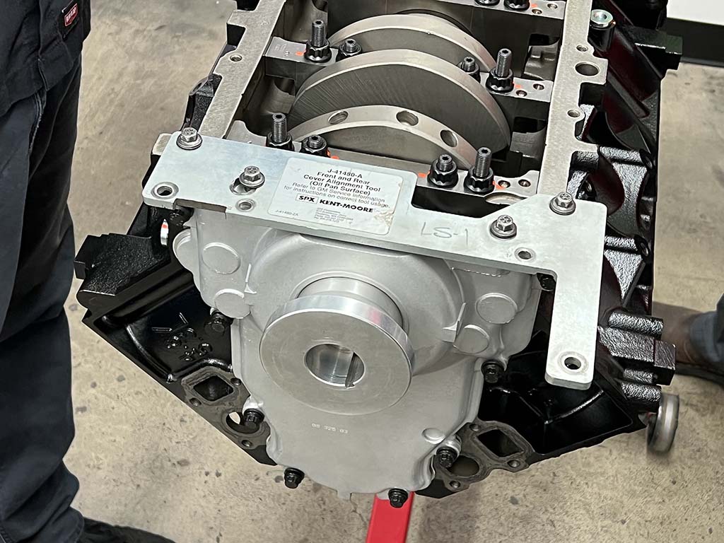
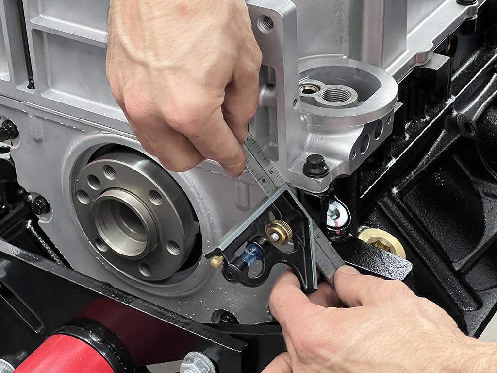
Working slowly, Martelli sneaks up on the magic number for each ring’s endgap, 0.018 inch for the top rings and 0.023 inch for the second rings, carefully deburring the ends as he goes. Each ring must be installed in the bore a handful of times and measured using a feeler gauge until the desired endgap is achieved.With the compression rings filed to Martelli’s satisfaction, installation of the rings can begin, starting with the oil control rings. First, the spring-like expander ring is installed, followed by the upper and lower rails. Martelli installs the two oil rail rings so that their endgaps are 180 degrees opposite. It should also be noted that the oil rings did not need to be filed to fit.Next, the Napier-style second ring is installed. Martelli ensures that any directional marking is pointed toward the top of the piston before inserting one end of the ring into the ring groove and then carefully rotating it into place.The top compression ring is installed in a similar manner. Martelli orients the top ring’s endgap at the top of the piston’s skirt, while the second ring is 180 degrees opposite.Once all the rings have been installed, Martelli is ready to begin dropping the slugs into their respective holes. A light coat of oil is applied to the rings and the piston, while a similar coat of assembly lube is applied to the upper and lower connecting rod bearings, before the piston is dropped into the cylinder bore, aided by an ARP piston installation tool.To provide plenty of clearance for the incoming connecting rod, the crank’s rod journal is oriented at the bottom of its stroke for the respective cylinder that is being assembled. Here, Martelli has lowered the piston assembly into place on the crankshaft before installing the rod cap and fasteners, slightly snug for now. Care is given to ensure the rod bearings are installed with the proper clearance for the crank’s fillet (the radius where the crank’s web meets the rod journal). The rods need to be installed with this fillet in mind as well as they are unidirectional.Once all eight cylinders have been assembled, Martelli begins the incremental torque sequence for each pair of ARP 2000 rod bolts, starting at 25 lb-ft and working from there for a final torque spec of 82 lb-ft.Next, Martelli checks the connecting rod side clearance using a feeler gauge. A reading of 0.022 inches between each rod means we’re in the clear. Note the torque striping on the rod bolts to denote that they’ve been properly torqued.We’ll be reusing the stock rear cover, with a new gasket from Summit (PN NAL-12639249). There are two tools that are used to install the front and rear covers to ensure they’re centered with the crank and aligned with the bottom oil rail of the engine block to prevent leaks. Here, the cover is installed with the ARP fasteners finger tight and the crankshaft centering tool in place.The second tool attaches to the bottom of the engine block and the rear cover and brings them in line with each other. The rear cover fasteners are now torqued to 18 lb-ft.With the rear cover in place, Martelli turns his attention to the front of the engine and, more precisely, to the camshaft. We’re using a Summit Pro LS hydraulic roller tappet camshaft (PN SUM-8715R1) with 222/234 duration at 0.050-inch lift and a 115-degree lobe separation. Martelli applies camshaft assembly lube to each lobe and bearing surface before carefully installing the camshaft in the block.The camshaft retaining plate (PN SUM-150106) controls the forward movement of the cam and is installed next. A dab of thread locker was applied to each bolt before they were torqued to 11 lb-ft.Two Woodruff keys are used to prevent the oil pump and timing gears from rotating on the crankshaft’s snout.The Cloyes crankshaft sprocket (PN CLO-S827) serves two functions on the LS-series engines; in addition to acting as a traditional timing gear it also serves to drive the oil pump.A GM camshaft sprocket (Summit PN ADO-12576407) is aligned to the crankshaft sprocket and attached via a Chevrolet Performance single-roller timing chain (PN NAL-12646386). Once again, ARP fasteners are used for performance and reliability, torqued to 26 lb-ft.Next, it’s time to install the Melling Performance High Volume oil pump (PN MEL-10296). Martelli preps the pump by applying a liberal amount of engine oil inside the pump to prevent cavitation on initial start-up …… before sliding the pump over the crankshaft sprocket. Martelli aligns the pump with the crankshaft by tightening the fasteners slightly snug and rotating the crankshaft 360 degrees, before torquing them to spec.The front of our block is now complete and it’s time to install the front cover.Using a new gasket (Summit PN SUM-G2628), ARP hardware, and similar installation tools as used to install and align the rear cover, Martelli installs the stock GM timing cover.We’re using the stock oil pan, baffle, and pickup for the moment, but clearance issues with the intended vehicle may call for a lower profile pan, such as Summit’s Pro LS oil pan (PN SUM-121200).Using a straightedge, Martelli ensures that the back of the pan and block are aligned since some bellhousings/transmissions bolt to both surfaces.Our 330ci iron block LS engine is now a fully assembled long-block!
We use cookies to ensure that we give you the best experience on our website. If you continue to use this site we will assume that you are happy with it.