
An Optimized PCV System for Street Engines Can Minimize Oil Leaks and Might Improve Driveabilty
By Jeff Smith – Photography by the Author
Positive Crankcase Ventilation (PCV) can easily qualify as the least interesting aspect of a gearhead’s inventory of hot rod romance parts. Many people think that this system’s only benefit is to keep oil vapors from escaping valve cover vents that create that annoying oil mist that coats your engine and permeates into the passenger compartment.
So why bother to investigate such a nothing topic? Because there is much more to the PCV valve system than appearances would indicate and there can be multiple advantages to focusing attention on this little known circuit. If you think that minimizing oil leaks, reducing oil usage, preventing crankcase sludge, perhaps improving throttle response, and basically helping engine efficiency is a good idea read on.
Let’s start with how a PCV valve system functions. All internal combustion engines create crankcase pressure–generally referred to as blow-by. This is formed when cylinder pressure leaks past the rings and forms a mist of oil in the crankcase. This pressure must be ventilated or the buildup will very quickly push out valve cover or pan gaskets and force oil past the front and rear main seals. All of which is annoying, leading to a never-ending task of cleaning the engine bay. Just ask the guys with rags tied around their valve cover breathers.
Before 1962 production cars employed a road draft tube that dumped this oil mist on the road. Next time you see a photograph of a Los Angeles freeway from the early ’60s, look for wide black stripes of oil oozing down the center of each lane. Just imagine how slippery those freeways were after the first rain of the season!
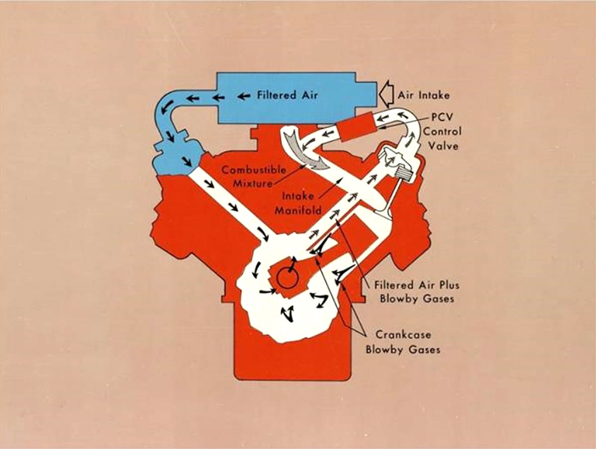
Beginning around 1962, the PCV valve became the first engine emission control device. It is a very simple valve using a tapered seat plunger held in place with a light spring. Most often the PCV valve was located in the valve cover. The valve uses manifold vacuum to meter a small amount of vacuum into the crankcase to evacuate vapors from the crankcase and into the intake manifold. Factory configurations use a filtered air inlet on the opposite side of the engine that uses ambient air pressure to help push the vapors through the PCV valve.
If the valve is properly designed for the engine package, it will create a slight vacuum in the crankcase. This helps minimize oil leaks. If the system does not work properly, or if the engine is merely vented, there will be pressure in the crankcase at all times.
A spring inside the valve determines the position of the tapered seat valve, which is affected by load. This simple design unfortunately makes these valves not adjustable and very application-specific. Selecting a PCV valve becomes somewhat of a guessing game. Today, that original list of thousands of individual PCV valve applications has been radically trimmed so that the same valve is now listed for every small-block from a lowly 307ci small-block Chevy all the way up to a 454 Rat motor.
When the Gen III LS small-block appeared on the scene in 1998 in Corvettes it didn’t take long to begin hearing tales about how these engines were collecting oil in the intake manifolds. Many assumed this was due to poor oil control from the thin piston ring design. This turns out to be not true. The reality was quite different.
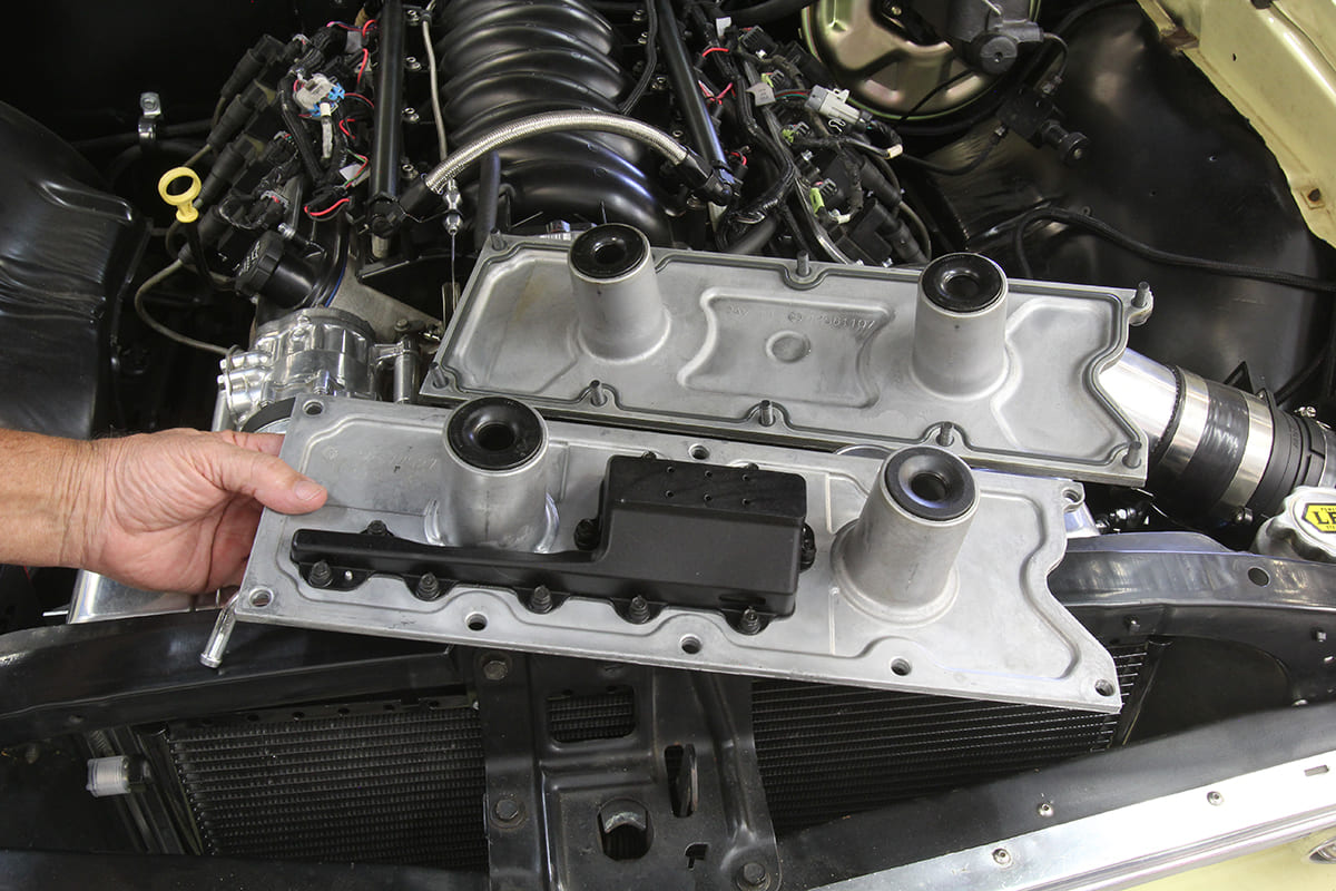
When GM designed the LS, engine compartment space for the Camaro and Corvette was tight and LS valve covers were designed with a minimal amount of clearance. This left little space for the oil separator inside the valve cover and engines began pulling liquid oil directly into the intake manifold. Some of this was burned and the rest pooled inside the intake manifold. Older truck engines with hundreds of thousands of miles have been found literally dripping with oil when removed.
This was not entirely the fault of the PCV valve but rather due to limited real estate inside the valve cover that prevented creating enough space to build an effective separator that could remove the oil before the vapor traveled through the valve and into the intake manifold.
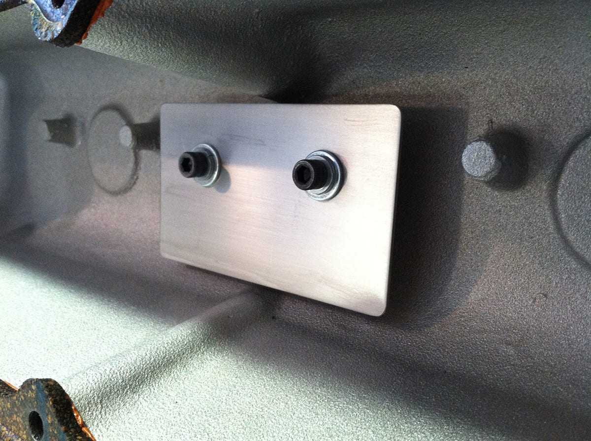
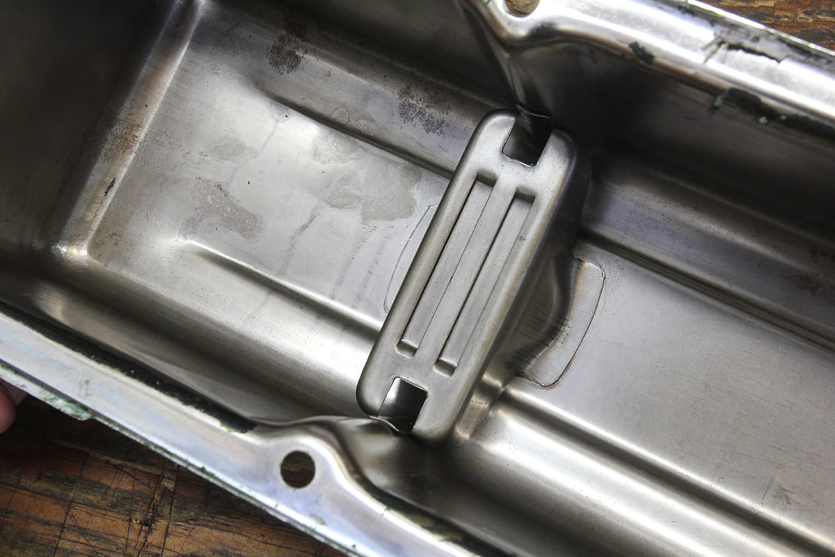
Matt Wagner’s experiments for creating an efficient oil separator inside a valve cover created this simple barrier. It is designed so its sides do not touch the valve cover and that it stands off from the top of the valve cover by at least ¾ inch. This slows the movement of the oil and air, allowing the oil to separate. If the clearances are too close, the air movement is fast enough to carry the oil with it into the PCV valve.
Testing performed by Matt Wagner, the designer of the M/E Wagner dual-flow PCV valve, revealed that most PCV valves do not perform as expected. Using a sophisticated flow meter Wagner tested aftermarket open breathers, three different production PCV valves, along with his own dual-flow valve. Testing indicated that breathers did not completely vent the system, allowing residual pressure in the crankcase. Evaluating the first two PCV valves revealed they only created vacuum in the crankcase between 20 and 30 percent of the time, which means there was pressure in the crankcase between 70 and 80 percent of operating conditions. A third valve performed better but still only managed to create vacuum during 70 percent of the test.

When Wagner tested his own valve, it established a vacuum to pull vapors from the crankcase 99 percent of the time. That last 1 percent was when the engine was operating at wide-open throttle (WOT) where engine vacuum drops to nearly zero in the intake manifold, which disables the PCV system. More specific test details are available on M/E Wagner’s website.
This test revealed there was a clear need for an adjustable PCV valve that would establish a sufficient flow that would create a vacuum in the crankcase. The Wagner dual-flow valve offers two levels of flow: one adjustable flow for idle and light throttle conditions when crankcase pressure should be minimal and the second “cruise” is a higher flow mode designed to initiate under hard throttle cruising conditions when manifold vacuum drops (and blow-by increases). The Wagner valve is beneficial because the optimal transition point between these flow modes can be tuned to each specific engine using a vacuum gauge. This combination of adjustments allows the user to completely tailor the PCV’s flow profile to their particular engine. Stock PCV valves only offer one airflow path that is not adjustable in any way.
This lack of sufficient vacuum in the crankcase is important because gasket leaks are amplified when pressure in the crankcase is sufficient to push the oil past the seals. Wagner’s website offers an example where a street rodder spent over $2,000 to rebuild his engine to solve an oil use problem that later was solved with an M/E Wagner dual flow valve.
In a more first-person evaluation, we have a ’90 350 TPI engine in an S-10 that is a California-legal engine swap. With a weak-performing PCV valve, the engine consistently pushed the dipstick out of the tube by roughly ¾ inch and leaked oil from the front cover seal. This occurred even after trying two different PCV valves. After adding an M/E Wagner two-stage PCV valve tuned to our engine, our front cover seal oil leak has all but disappeared, and the dipstick now remains where it belongs.
Surprisingly, in addition to these improvements, our minor but annoying off-idle stumble when the clutch is engaged has all but disappeared. All of these improvements were the result of a change to a simple adjustable PCV valve that took less than 10 minutes to tune and install.
As mentioned earlier, early LS engines tend to fall into this excessive oil consumption trap and the more-efficient Wagner PCV valve may actually aggravate those issues. This is because along with the additional flow through the crankcase is the inevitable oil that is pulled along with the vapor. Wagner suggests combining a vapor separator tank along with the dual-flow PCV valve.
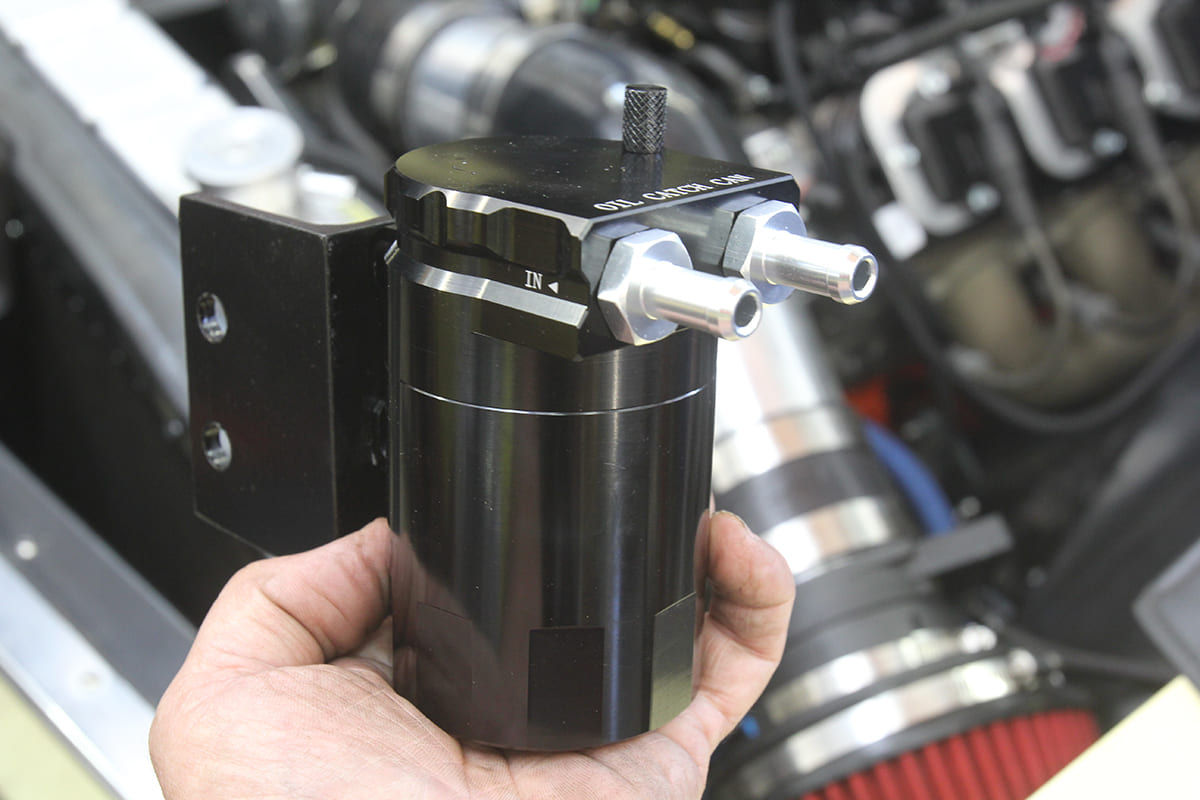
The separator is really nothing more than a small reservoir with inlet and outlet fittings and a small drain petcock on the bottom. We were going to build one out of a used A/C driver canister when a friend discovered an inexpensive oil separator available through Amazon that has a threaded, removable body sealed with an O-ring that also features a handy dipstick to tell you when the reservoir needs draining. For around $30, this is a great little unit. This also allows you to adjust the idle circuit on the Wagner valve to be slightly more aggressive, using the reservoir to separate the oil from the vapor.
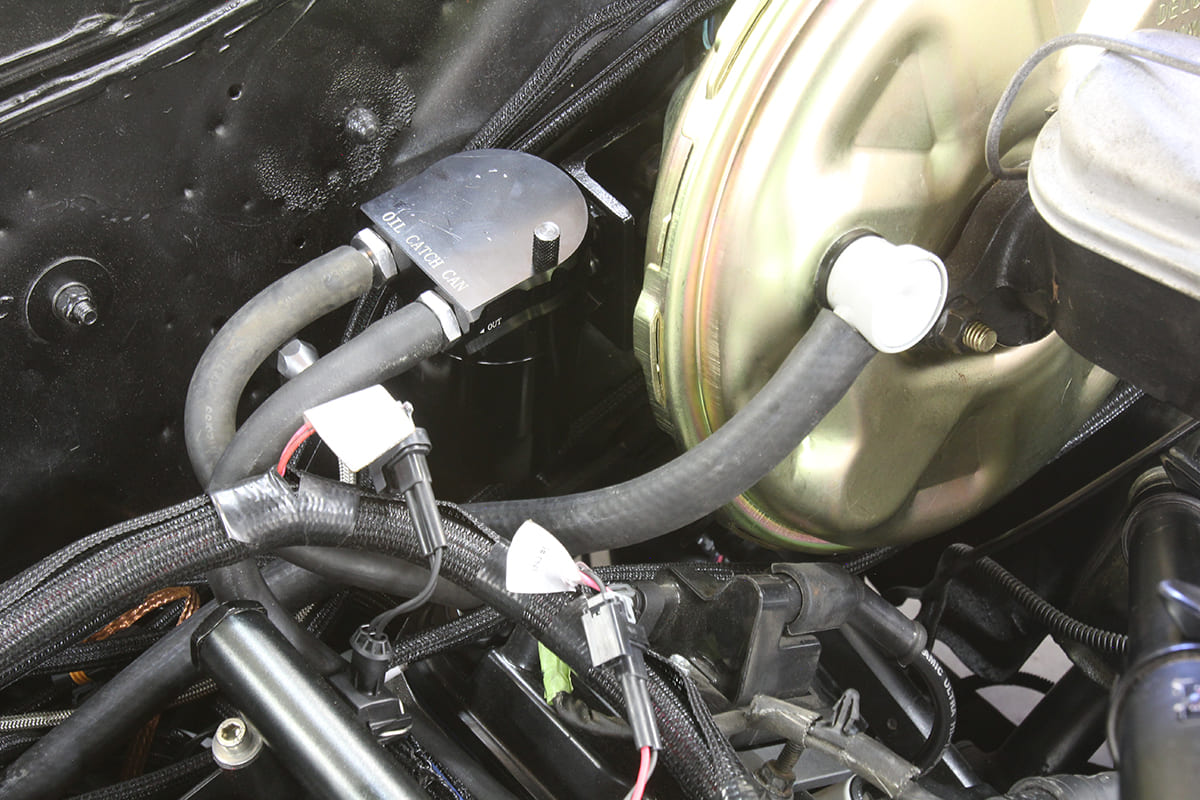
We decided to mount one of these reservoirs on a ’67 Chevelle with a 5.7L LS swap by making an aluminum bracket that attaches to the brake booster mount bolts. We substituted better, heavier wall vacuum hose to replace the cheesy stuff the reservoir was shipped with. That cheap hose will collapse under vacuum and render the entire system inoperative, so we didn’t use it.
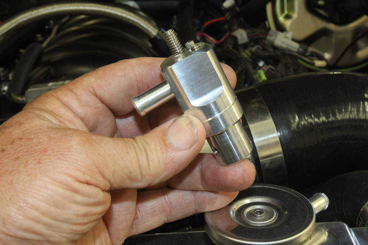
We plumbed a filtered air inlet line from the throttle body that sources upstream of the throttle blade and ran a Dorman PCV valve hose with molded bends to prevent kinking into the passenger side front LS valve cover inlet. Then, on the driver side rear position, we placed one of Wagner’s billet PCV valves and plumbed it to the outlet of the oil separator. We then hooked a ½-inch-diameter vacuum hose from the intake manifold to the vapor separator inlet side of the vapor separator.
If after a few hundred miles of use with the billet PCV valve you find the system is still pulling quite a bit of oil through the separator, one improvement for Gen III LS engines might be to use a larger vapor separator. GM came up with a lifter valley cover for the pre-AFM Gen III LS engines that offers a larger unit in the lifter valley. The external nipple would then be attached to the inlet of an inline PCV valve that would connect the vapor separator canister. This provides an additional way to minimize the amount of oil that could enter the engine. Wagner offers an adapter for the billet PCV valve to be configured in a horizontal position.
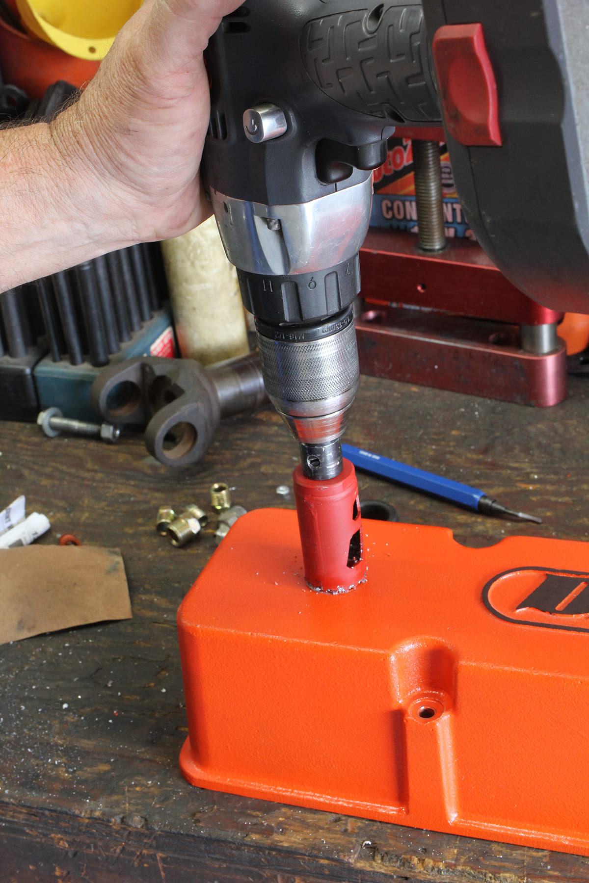
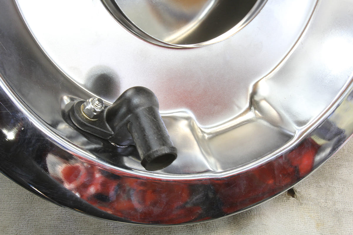
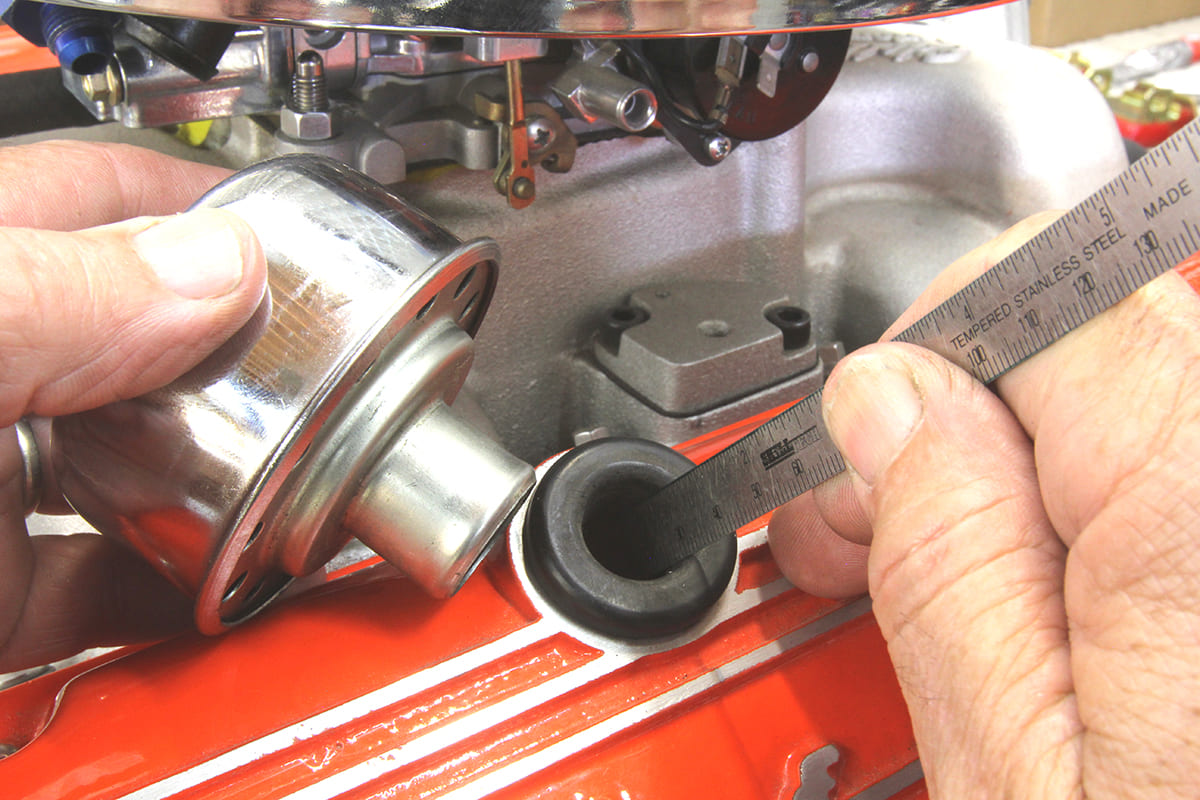
Of course, small- and big-block Chevy engines can also benefit from the application of a strong adjustable PCV valve and most of the above information would apply. Some enthusiasts may be tempted to use a simple breather for the inlet side of the system but the best route is to duplicate the factory arrangement with a fitting located on the inside of a typical 14-inch open element air cleaner base. This ¾-inch inlet tube offers a large, unrestricted inlet for the PCV valve while also filtering the air to ensure it’s clean. An oil filter engineer once told us that the world’s best oil filter is a really good air filter and that same logic applies to the PCV system.
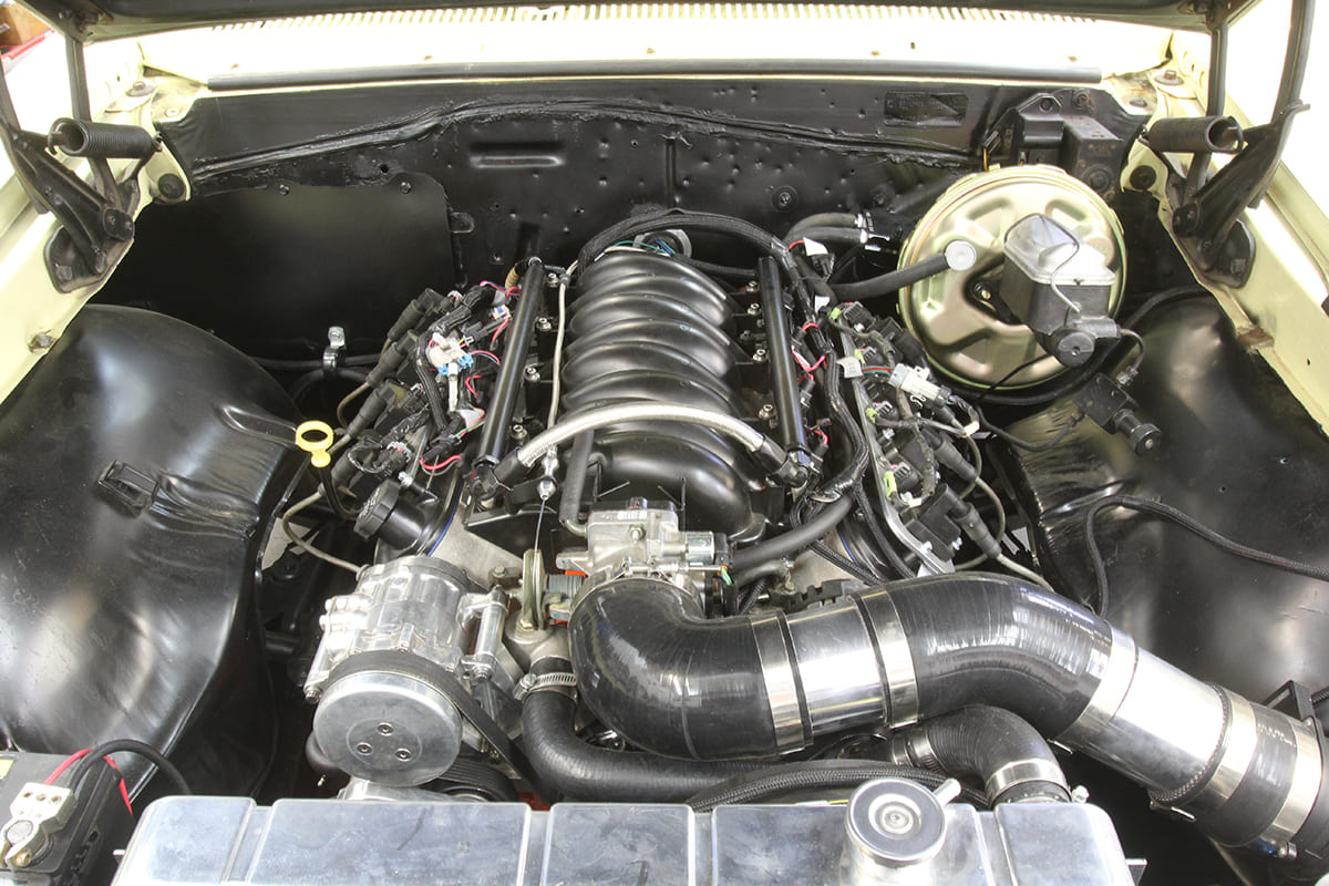
This is the LS-swapped 5.7L engine in our friend Eric Rosendahl’s ’67 Chevelle 300 that includes one of Wagner’s billet PCV valves.
The key, then, is adjusting the Wagner PCV valve according to their instructions and then enjoying the advantages of fewer oil leaks, a cleaner running engine, and perhaps even slightly improved throttle response. And all that is affected by what many enthusiasts have never bothered to think about–the simple PCV valve.
Parts List
| Component | PN |
| M/E Wagner billet, dual flow, PCV valve | DF-17 |
| M/E Wagner inline adapter | DF-17 INL |
| M/E Wagner rebuild kit | DF-17 RBK |
| Dorman LS PCV valve hose | 46056 |
| Ruien aluminum PCV separator/reservoir | US-OOCC024 |
| Gen III LS6 lifter valley cover | 12577927 |
| Edelbrock ¾-inch PCV air cleaner fitting | 1205 |
| Grainger 1 3/16-inch bi-metal hole saw | 53WM56 |
Source
M/E Wagner Performance;
(570) 899-4544
mewagner.com